电源模块Tracopower选型指南
- 格式:pdf
- 大小:4.88 MB
- 文档页数:33

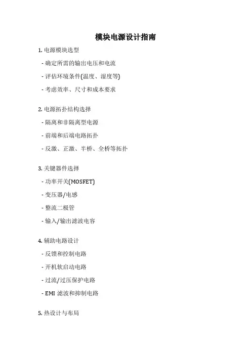
模块电源设计指南1. 电源模块选型
- 确定所需的输出电压和电流
- 评估环境条件(温度、湿度等)
- 考虑效率、尺寸和成本要求
2. 电源拓扑结构选择
- 隔离和非隔离型电源
- 前端和后端电路拓扑
- 反激、正激、半桥、全桥等拓扑
3. 关键器件选择
- 功率开关(MOSFET)
- 变压器/电感
- 整流二极管
- 输入/输出滤波电容
4. 辅助电路设计
- 反馈和控制电路
- 开机软启动电路
- 过流/过压保护电路
- EMI滤波和抑制电路
5. 热设计与布局
- 功率损耗计算
- 热耗散设计(散热芯片、风扇等)
- 元器件布局和走线
6. 安全认证与EMC
- 安全标准(UL/EN等)
- EMC/EMI标准
- 绝缘和耐压设计
7. 测试与调试
- 原理图与PCB设计验证
- 功能测试与故障诊断
- 效率、纹波、EMI测试
8. 文档和标准遵从
- 设计文件整理
- 安全和EMC测试报告
- 产品标准符合性声明
设计模块电源需要全面考虑功能、可靠性、成本和法规要求,上述设计指南涵盖了关键的设计步骤和注意事项。
How to Pick the Right Microcontroller Based on Low-PowerSpecificationsIntroductionChoosing the right ultra-low-power microcontroller (MCU) for your next embedded design can be a confusing task when you compare claimed current consumption specifications in a myriad of data sheets provided by MCU vendors. In many cases, developers initially scan the first page of a data sheet as a reference point to gain basic information about an MCU, including peripherals, operating speed, package information, number of GPIOs and power characteristics. This approach works well to assess an MCU’s overall functionality, but it is not particularly useful when trying to gauge low-power characteristics.To get a broader view of an M CU’s true low-power operation, developers must take into consideration current consumption, state retention, wake-up time, wake-up sources and peripherals that are capable of operating while in low-power mode. Developers must compare a common operating mode to gain a balanced, apples-to-apples comparison among competing low-power MCUs. It is also important to take into consideration any additional functionality or peripherals that can reduce total system power and available evaluation tools that can make an engineer’s job easier.Microcontroller vendors will usually list the lowest power achievable on the first page of the data sheet. Although the device may be capable of achieving the specification in the data sheet, the actual operating mode may not be practical and useful in a real-world application. Some of the non-advertised features of the lowest power mode may include a very slow wake time, no state or RAM retention, or a reduced operating voltage range.To get around the variety of low-power specifications, developers must identify a common operating mode consisting of two sections: electrical specifications and low-power functionality.Comparing Electrical Specifications of MicrocontrollersThe electrical specifications are available in the data sheet, but determining which specifications are relevant may require some digging. Usually the electrical specifications are organized by vendor-specific power mode. This makes assessment slightly more difficult, as it requires knowledge and familiarity with the functionality of each power mode.In general, it is beneficial to define a set of operating conditions and then map them to a power mode. For example, the developer might define the following set of operating conditions:∙Sleep mode current consumption with state and RAM retentiono All other peripherals disabled∙Sleep mode current consumption with RTC running with state and RAM retentiono RTC enabled and running all other peripherals disabled.∙Wake time∙Supply voltage rangeOnce the operating conditions are clearly defined, it should be easy to determine the applicable vendor-specific power mode.Additional Low-Power FunctionalityThe second section, low-power functionality, is not as easy to locate in the vendor’s documentation and may be spread across the data sheet and reference manual. Examples of low-power functionality include: ∙Available wake sources∙How code resumes execution∙Peripherals capable of operating in sleep mode.Once the common operating mode has been clearly defined, developers can begin to examine the documentation in more detail.While going through this exercise of compiling data, keep in mind that there may be some MCU-specific features that can further optimize an application for ultra-low power. Optimizations may reduce bill of material (BOM) costs, provide longer product life or provide greater design flexibility. For example, an on-chip dc-dc converter can efficiently provide power to the system and decrease power consumption. This can enable the use of smaller batteries, which will decrease the overall BOM costs, or provide power budget flexibility. A variety of wake sources can provide design flexibility and allow the microcontroller to stay in the lowest power mode as long as possible, further reducing the average current consumption of the application.Allowing firmware to scale the internal supply voltage is another optimization knob available to the developer. If an MCU is operating at a slow frequency, it may be possible to decrease the supply voltage and save power. Selective clock gating allows hardware blocks to be disconnected from the active circuits, preventing inactive peripherals from consuming power. These types of features are not comprehended by supply current specifications that are commonly used to rank low-power MCUs, but are critical to achieving the lowest overall system power consumption.Reducing Complexity Using ToolsAs MCUs become more and more configurable to achieve the lowest power consumption, they also can become more complex. To cope with this increased complexity, developers should take a close look at the evaluation platforms available for an MCU and the overall ease of implementing a solution. For example, the development board and software tools used to program the MCU should be intuitive and easy-to-use. Hardware that is difficult to understand or use is not likely to lead to an easy firmware development process. From a firmware perspective, MCU vendors should supply firmware examples that can recreate specifications from the data sheet. If advertised current consumption specifications cannot be recreated on an evaluation platform, it is likely that it will be just as difficult (if not impossible) to configure the MCU to achieve these numbers on custom hardware. Giving customers a variety of code examples that can be used as a starting point for their code development can reduce time-to-market and help engineers learn to use a device.Graphical configuration tools can aid in development and help the developer gain a deeper understanding of an MCU. When developing low-power applications, it is helpful to know where the total consumed power is going. This information is useful because it highlights what aspect of a design needs to be further optimized and can also help the developer understand the overall architecture of the device. Ideally, low-power configuration tools could give tips on further reducing power as well as highlight any configuration errors that were detected throughout the configuration process. For example, the Power Estimator utility within Silicon Labs’ AppBuilder graphical configuration tool provides Power Tips that give configuration guidance and a power-budget pie chart showing how much power is consumed and which peripherals are consuming the power. As configuration changes are made, the pie chart automatically updates.Figure 1. Power Estimator Enables Developers to Optimize for Lowest Current Consumption To facilitate the microcontroller comparison process, the following table provides a list of common operating modes, as well as system-level optimizations and development tools available for Silicon Labs’32-bit SiM3L1xx MCUs based on the ARM® Cortex™-M3 core.SummaryEvaluating and selecting a microcontroller for a low-power application requires more than a quick scan of the first page of the data sheet. Determining which MCU provides the lowest overall system power requires developers to know the device’s supply current specifications, as well as any system-level optimizations that can reduce the overall supply current.Unfortunately, each MCU vendor specifies operating conditions differently and in some cases advertises a low-power number that is available in an unusable mode. Using a common operating mode to compare MCUs will prevent developers from being misled by vendor claims of ultra-low-power operation.Once the electrical characteristics of a device are understood and quantified, developers should take a look at the evaluation platform and software tools available. These considerations are crucial in getting an engineering team up and running quickly and should be included in the final microcontroller selection process. Find out more about Silicon Labs’ microcontrollers, including 8-bit and 32-bit MCUs at/mcu.# # #Silicon Labs invests in research and development to help our customers differentiate in the market with innovative low-power, small size, analog intensive, mixed-signal solutions. Silicon Labs' extensive patent portfolio is a testament to our unique approach and world-class engineering team. Patent: /patent-notice© 2013, Silicon Laboratories Inc. ClockBuilder, DSPLL, Ember, EZMac, EZRadio, EZRadioPRO, EZLink, ISOmodem, Precision32, ProSLIC, QuickSense, Silicon Laboratories and the Silicon Labs logo are trademarks or registered trademarks of Silicon Laboratories Inc. ARM and Cortex-M3 are trademarks or registered trademarks of ARM Holdings. ZigBee is a registered trademark of ZigBee Alliance, Inc. All other product or service names are the property of their respective owners.。
TOL 10-MCOpen Frame Power SuppliesTOL Series, 10—300 WattFeatures◆ Small and compact PCB construction ◆ Optional with chassis and cover ◆ Universal input 85–264 VAC,◆ Output voltage adjustable◆ Compliance to EN 61000-3-2 (PFC)◆ EMI meets EN55022, Class B andFCC, Level B◆ Short circuit and overvoltage protection ◆ International safety standards ◆ Industrial quality standard ◆3-year product warrantyThe TOL Series switching power supplies are the best choice for many space critical applications. They feature ultra-compact dimensions and a low profile.As an accessory a chassis and cover kit for self-installation is available for all mo-dels. To make installation even more simple, prewired mating output/input con-nectors with flying leads are also offered as an accessory. Compliance with inter-national safety standards (CE/UL) and EMC specifications qualify this product for worldwide use. A very high reliability is guaranteed by the use of industrial quality grade components and excellent thermal management..Open Frame Power SuppliesTOL Series 10–300 WattInput voltage range 85 – 264 VACInput frequency 47 – 63 HzRecommended circuit breaker 10 – 150 Watt models: 6 A(characteristic C) or slow blow fuse 300 Watt models:10 AOutput voltage adjustment range ±10 %Regulation – Input variation0.5 % max.– Load variation (10–100%)0.8 % max.Ripple and noise (20 Mhz Bandwidth) 5 VDC output models:100 mV pp max.12/24 VDC output models:180 mV pp max.48 VDC output models:300 mV pp max. (TOL 300: 600 mV pp max) Output current limitation (except for F versions)105 % – 140 % of Inom.Short circuit protection – 10 to 30 Watt models:hiccup mode, indefinite (automatic recovery) – 50 to 300 Watt models:constant current (automatic recovery) Overvoltage protection 115 – 135 % Vout nom.Capacitive load – TOL 1010’000 µF max. (24 Vout model: 2’000 µF)– TOL 1515’000 µF max. (24 Vout model: 6’000 µF)– other models18’000 µF max.Temperature ranges – Operating temperature–10°C to +60°C (TOL 150: –10°C to +50°C) – Derating above +50°C 3 %/K (TOL 150: 1.5 %/°C above 35°C)– Storage (non operating)–20°C to +70°CTemperature coefficient 0.02 %/KEfficiency 75 % typ.Humidity (non condensing)20 % – 90 % rel. HSwitching frequency 100 kHz typ. (PWM)Hold-up time 20 ms typ. at full loadIsolation voltage – Input / output3‘000 VAC for 1min.– Input / FG (or case)2’000 VAC for 1min.– Output / FG (or case)500 VDC for 1min.Isolation resistance 100 MOhmLeakage current 0.6 mA RMS typ. / 230 VAC / 60 Hz Electromagnetic compatibility – Conducted input RI suppression EN 55022, class B; FCC Part 15, level B (EMC) Emission – Harmonic current emissions IEC/EN 61000-3-2, class D Electromagnetic compatibility– Electrostatic discharge IEC/EN 61000-4-2 8kV / 15kV(EMC) Immunity – Surge immunity IEC/EN 61000-4-5 2kV / 4kV Environmental compliance – Reach /products/tol-reach.pdf – RoHS RoHS directive 2002/95/ECSafety standardsEN 60950-1, UL/cUL 1950 File e188913Reliability, calculated MTBF (MIL-HDBK-217F , ground benign) – TOL 10 / TOL 15: > 650’000 h at +25°C – TOL 30: > 500’000 h at +25°C – TOL 50 / TOL 75: > 375’000 h at +25°C – TOL 100 / TOL 150: > 350’000 h at +25°C TOL 300: > 260’000 h at +25°CRemote ON/OFFOn: 5 VDC (input resistance 1 KOhm) (available as option for models TOL30/50/75/100/150/300) Off: 0 VDC or open circuitRemote sensing (only TOL300 models)– without sens line: previred connector included– with sens line: use Molex housing/pin 67261-0400 /67262 to connect sens line at P54Vibration IEC 60068-2-6,5-10 Hz with 10mm amplitude2 gn, 60 sweeps of 10-55 Hz, each axis Shock resistanceIEC 60068-2-27, 20 gn each axisOpen Frame Power SuppliesTOL Series10–300 WattOpen Frame Power SuppliesTOL Series 10–300 Watt TOL Standard open Frame VersionTOL Standard open Frame VersionTOL Standard open Frame VersionTOL Standard open Frame VersionOpen Frame Power SuppliesTOL Series 10–300 Watt TOL 10 standard open frame versionWeight 75 g (2.6 oz)Weight 170 g (17.6 oz)Open Frame Power SuppliesTOL Series 10–300 Watt TOL 15 standard open frame versionWeight 95 g (3.4 oz)Weight 210 g (7.4 oz)Open Frame Power SuppliesTOL Series 10–300 Watt TOL 30 standard open frame versionWeight 200 g (7.1 oz)Weight 280 g (9.9 oz)Open Frame Power SuppliesTOL Series 10–300 Watt TOL 50 standard open frame version210 g (7.4 oz)Weight 410 g (14.5 oz)Open Frame Power SuppliesTOL Series10–300 WattTOL 75 standard open frame versionWeight 520 g (18.3 oz)TOL 100 standard open frame versionWeight 380 g (13.4 oz)TOL 100 with chassis / cover optionSpecifications can be changed any time without notice.4 x ø3.5575 (2.95)(FG)565 ±0.5(2.56 ±0.02)531(P1)on/off control connection (optional)Voltage adjustment(P53)12(P52)(P51)1212 ±0.5 (8.35 ±0.02)222 (8.74)37 (1.46)3 m a x .(0.12 m a x .)55 ±0.52535 ±0.51585 (3.35)4 x M4thread2 x ø4.5(P1)176(0.2)(0.2)(0.59)(1.38 ±0.02)(0.98)(2.17 ±0.02)(P51)(P52)43 ±0.5(1.69 ±0.02)2 x M4threadø4.5201551 (2.00)4.5(0.18)(0.59)(0.79)-Vout+VoutN 235 ±0.5 (9.25 ±0.02)9(0.35)252 (9.92)4.5(0.18)LTOL 150 standard open frame versionTOL 150 with chassis / cover optionWeight 500 g (17.5 oz)Weight 830 g (29.5 oz)Specifications can be changed without noticeRev. December 13. 2013+V out-V outon/off control connection (optional)Voltage adjustment Remote sensing(P53)12(P54)14-Vout ref.-Vout sens+Vout ref.+Vout sens108 (4.25)594 ±0.5(3.70 ±0.02)(0.2)5(0.2)7(0.28)6 x ø3.5245 ±0.5 (9.65 ±0.02)255 (10.04)101 ±0.5 (3.98 ±0.02)22 ± 0.5(0.87 ±0.02)47 (1.85)3 m a x .(0.12 m a x .)98 ±0.5(3.86 ±0.02)118 (4.65)12(0.47)95 ±0.5(3.74 ±0.02)59 ±0.5(2.32 ±0.02)75 ±0.5(2.95 ±0.02)22(0.87)2x ø 4.5281761 (2.40)4.5(0.18)(0.67)(1.10)4 x M4thread271 ±0.5 (10.67 ±0.02)7(0.28)285 (11.22)ø 4.52 x M4threadN LTOL 300 standard open frame versionWeight 1000 g (35 oz)Weight 1400 g (50 oz)TOL 300 with chassis / cover optionTOL 10-MC。
MOSFET驱动器TPS28225DR特征:8引脚高频4-amp库同步MOSFET驱动器广泛的门驱动电压:4.5V至8.8V最好的效率在7v到8V宽功率系统输入电压:3v到27v宽输入PWM信号:2.0v到13.2v振幅能够驱动MOSFET开关的电流>=每相40A高频操作:14ns传播延迟和10ns的上升/下降时间允许FSW - 2MHz 可小于30 ns输入PWM脉冲的传播低侧驱动器接收器电阻(0.4Ω)防止相关直通电流DV / DT三态PWM输入为了关闭功率级节省空间的启用(输入)和电源良好(输出)在相同的引脚信号热关机欠压保护内部自举二极管经济的SOIC - 8和热增强3毫米x 3毫米DFN 8包高性能的替代流行的三态输入驱动器应用:多相DC-DC转换器的模拟或数字控制桌面和服务器Vrms和evrds笔记本电脑/笔记本管理用于隔离电源的同步整流典型应用对于互补驱动MOSFET同步整流驱动器多相同步降压转换器输入电源电压范围VDD:启动电压Vboot:相电压:DC:脉冲<400ns,E=20uJ 输入电压范围,输出电压范围输出电压范围ESD额定值,HBMESD额定值,HBM的ESD额定值,CDM 连续总功耗见耗散评级表经营虚拟结温范围,Tj工作环境温度范围,TA铅的温度TPS40210,适用于升压,反激式,SEPIC,和LED 驱动器拓扑宽输入电压:4.5 V至52 V振荡器频率可调固定频率电流模式控制内部斜率补偿集成的低侧驱动器可编程闭环软启动过流保护700 mV参考(tps40210)低电流禁用功能输入电压VDD:4.5-52V(推荐)绝对最大范围参考电压:VfbTPS40210 COMP = FB, 4.5 ≤ V VDD ≤ 52 V, T J = 25 C min 693 typ700 max707V VDD输入电压范围 4.5 到 52 V4.5 ≤ V VDD ≤ 52 V, 没有开关, V DIS < 0.8 1.5 到2.5 mAI VDD 工作电压范围 2.5 ≤ V DIS ≤ 7 V 10 到20 AV VDD < V UVLO(on), V DIS < 0.8 小于530 A欠压锁定V UVLO(on) 打开阀值电压 4.00 4.25 4.50 VV UVLO(hyst) UVLO滞后 140 195 240 mV振荡器振荡器频率范围 30 1000khz振荡器频率 R RC = 182 kΩ, C RC = 330 pF 260 300 340V SLP 斜率补偿范围 520 620 720 mVPWM 最小脉冲范围 V VDD = 12V(1) 275 400 nsV VDD = 30V 90 200 nst OFF(min) 最小关机时间 170 200 nsV VLY 谷值电压 1.2 VV SS(ofst)补偿电压 from SS pin to 误差放大器 input 700 mV软启动充电电阻 320 430 600 kΩ软启动充电电阻 840 1200 1600 kΩ单位增益带宽积 1.5 3.0 MHz开环增益 60 80 dB输入电流 100 300 nA灌电流 V FB = 0.6 V, V COMP = 1 V 100 250 AV ISNS(oc) 过流阀值ISNS pin) 4.5 ≤ V DD < 52 V, -40 C ≤ T J ≤ 125 C 120 150 180 mV PARAMETER TEST CONDITIONS MIN TYP MAX UNITCURRENT SENSE AMPLIFIERA CS 当前的读出放大器增益 4..2 5.6 7.2 V/VI B(ISNS) 输入偏流 1 3 ADRIVERI GDRV(src) 门驱动源电流V GDRV = 4 V, T J = 25 C 375 400 mAI GDRV(snk) 门驱动器反向电流V GDRV = 4 V, T J = 25 C 330 400 mA线性调节器V BP 旁路电压输出 0 mA < I BP < 15 mA 7 8 9 VDISABLE/ENABLEV DIS(en) 开启电压 0.7 1.3 VV DIS(hys)滞后电压 25 130 220 mVR DIS DIS引脚下拉电阻 0.7 1.1 1.5 MΩ终端 I/O 描述NAME NO.COMP 4 O 误差放大器的输出。
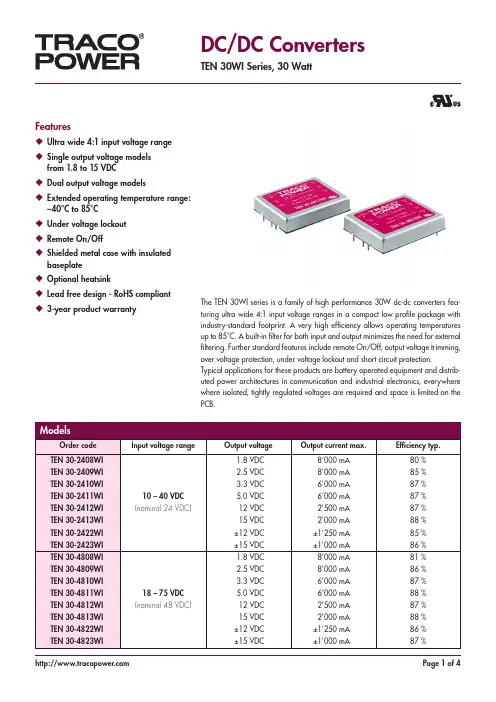
Features◆ Ultra wide 4:1 input voltage range ◆ Single output voltage modelsfrom 1.8 to 15 VDC◆ Dual output voltage models◆ Extended operating temperature range:–40°C to 85°C◆ Under voltage lockout ◆ Remote On/Off◆ Shielded metal case with insulatedbaseplate◆ Optional heatsink◆ Lead free design - RoHS compliant ◆ 3-year product warrantyDC/DC ConvertersTEN 30WI Series, 30 WattThe TEN 30WI series is a family of high performance 30W dc-dc converters fea-turing ultra wide 4:1 input voltage ranges in a compact low profile package with industry-standard footprint. A very high efficiency allows operating temperatures up to 85°C. A built-in filter for both input and output minimizes the need for external filtering. Further standard features include remote On/Off, output voltage trimming, over voltage protection, under voltage lockout and short circuit protection.Typical applications for these products are battery operated equipment and distrib-uted power architectures in communication and industrial electronics, everywhere where isolated, tightly regulated voltages are required and space is limited on the PCB.Input current at no load 1.8 Vout models:35 / 20 mA typ.(nominal input 24/48 Vin) 2.5/3.3 Vout models:40 / 25 mA typ.other models:70 / 45 mA typ.Input current at full load 1.8 Vout models:760 / 380 mA typ.(nominal input 24/48 Vin) 2.5/3.3 Vout models:1030 / 510 mA typ.other models:1500 / 750 mA typ.Input voltage variation (dv/dt) 5 V/ms, max.(complies with ETS 300 132 part. 4.4)Under voltage lockout 24 Vin models:7 VDC min. / 8 VDC typ. / 9.2 VDC max.48 Vin models:15 VDC min. / 16 VDC typ. / 17.5 VDC max. Surge voltage (100 msec. max.)24 Vin models:50 V max.48 Vin models:100 V max.Conducted noise (input)EN 55022 level A, FCC part 15, level A(with external components)Please refer to Application note: /overview/ten30wiESD (input)EN 61000-4-2, perf. criteria BFast transient (input)EN 61000-4-4, perf. criteria ASurge (input)EN 61000-4-5, perf. criteria BVoltage set accuracy ±1 %Output voltage adjustment ±10 %Regulation – Input variation Vin min. to Vin max. ±0.5 % max.– Load variation 10 – 100 %:single output models:±0.5 % max.dual output models:±1.0 % max. (balanced load)±5 % max. (Load cross variation 25 % / 100 %) Temperature coefficient ±0.02 %/KRipple and noise (20 MHz Bandwidth): 75 mVpk-pk max.Start up time (nominal Vin and constant resistive load)10 ms typ.Transient response setting time (25% load step change)300 µs typ.Short circuit protection indefinite (automatic recovery)Over load protection 150 % of Iout max typ. foldbackThermal shutdown at +115°C typOver voltage protection 1.8, 2.5 & 3.3 V output models: 3.9 V5.0 V output models:6.2 V12 V output models: 15 V15 V output models:18 VMinimum load (only for dual output models)10% of rated max current (operation at lower loadcondition will not damage these converters, however,they may not meet all listed specifications) Capacitive load 1.8 / 2.5 Vout models:65’000 µF max./ 33’000 µF max.3.3 / 5.0 Vout models:19’500 µF max./ 10’200 µF max.12 / 15 Vout models:3’300 µF max./ 1’100 µF max.±12 / ±15 Vout models:±1’000 µF max./ ±680 µF max. (per output)Temperature ranges – Operating–40°C to +85°C (with derating) – Case temperature +100°C max.– Storage–55°C to +105°C Thermal impedance – with heat-sink TEN-HS2 8.24 K/Watt– without heat-sink10 K/Watt Humidity (non condensing)95 % rel H max.Reliability, calculated MTBF (MIL-HDBK-217F , at +25°C, ground benign) >750’000 h Isolation voltage (60sec.) – Input / Output 1‘500 VDC Isolation resistance – Input / Output >1‘000 M Ohm Isolation capacitance – Input / Output 1000 pF max.Remote On/Off – On: 3.5 ... 12 VDC or open circuit.– Off:0 ... 1.2 VDC or short circuit pin 3 and pin 2– Off idle current: 3 mA typ.Switching frequency 300 kHz typ. (pulse width modulation PWM)Vibration10–55 Hz, 2G, 30 minutes along X,Y,Z Safety approvals UL 60950, IEC/EN 60950, complianceup to 60 VDC input voltage (SELV limit)– Certification documents /overview/ten30wi Environmental compliance – Reach /info/reach-declaration.pdf– RoHSRoHS directive 20011/65/EUTrim+VoutTrim- VoutTrim upRu [kohm]*output 1.8V 2.5V 3.3V 5.0V +5% 1.2 4.3 6.8 4.7+10% 0.068 0.82 1.5 0.56output 12V 15V ±12V ±15V +5% 47 47 27 33+10%8.2 6.8 2.2 2.7Trim downRu [kohm]* output 1.8V 2.5V 3.3V 5.0V –5% 1.8 6.8 8.2 5.6–10% 0.1 0.82 0.68 0.68output 12V 15V ±12V ±15V –5% 56 56 33 39–10%5.6 2.2 2.7 3.3*approximate valuesSupporting documents: /overview/ten30wiCasing material copper, nickel plated Baseplate material none conductive FR4Potting material epoxy (UL 94V-0 -rated)Weight48 g (1.69 oz)Soldering temperaturemax. 265°C / 10 sec.Heat-sink TEN-HS2Dimensions in [mm], () = InchPin diameter: 1.0 ±0.05 (0.02 ±0.002)Pin pitch tolerances: ±0.35 (±0.014)Case tolerances: ±0.5 (±0.02)Note:The product label on converter has to be removed before mounting the heat-sink. For volume orders converters will be supplied with heat-sinks already mounted. Please con-tact factory for quotation. Separate heat-sinks are only available for prototypes and small quantity orders.Order code: TEN-HS2 (cont.: heat-sink, thermal pad, 2 clamps)Material: Aluminum Finish: Anodic treatment (black)Weight: 19 g (0.67oz) (without converter)。
AC/DC 模块开关稳压器不同凡响的产品组合RECOM - 拥有超过35年的成功经验在过去20年里,几乎在所有的电子产品应用如工业自动化,交通运输工程,电信,数据处理,测量测试设备和医疗电子等领域直接采用DC/DC 转换器模块已经越来越普遍。
甚至对于大批量生产,也很少有公司愿意花精力去开发他们自己的DC/DC 转换器,特别是鉴于目前产品需要遵守严格的国际标准。
对于功率转换器件,RECOM 公司一直非常专注于客户需求及意愿,在过去的十年里已投资数百万用于产品开发,质量保证实验室建设以及全模块供他们使用。
我们的一些创新型解决方案如R-78开关稳压器一直就是行业标准。
对于这一点,R-78被我们的众多竞争对手抄袭就是最好的证明。
如果您需要一个定制解决方案,我们的产品工程师将无比荣幸地向您提供帮助和支持。
我们的开发团队一直以满足客户需求为本。
这也是技术支持和正确的售前建议是我们第一要务的原因所在。
球销售业务的拓展。
这意味着我生产地点,我们能够以一流的支持水平和极具性价比的价格提供目前市场上最可靠的产品。
现在,我们的客户可以精选市面上的转换器(包括输出功率高达60W 的DC/DC 和AC/DC 转换器)以及各种开关稳压器和LED 驱动器们非常贴近于遍布全球的客户的RECOM 的产品和工艺满足最高国际标准,并已获得一些全球领先的认证机构的认证。
但是对于RECOM 而言,这仅仅只是开始,因为RECOM 的目标是零缺陷。
虽然这听起来有点像天方夜谭,但是我们仍在不遗余力地在为实现这个目标而不懈努力。
这不仅适用于制造和质量控制阶段,而且还涵盖产品开发过程。
下面这个最近的例子可以证明我们志在满足严格质量标准的决心有多大。
恒温恒湿箱中的原型高加速寿命(HALT)试验表明,如果在高温/高湿环境下工作,产品可能出现潜在问题。
RECOM的目标:没有最好,只有更好!但是产生这个问题的原因尚不明确,因为我们在每个产品中所用的所有元件全部都是来自领先供应商的经过验证的元器件。

Product Portfolio 2017 MedicalPAGE 2TRACO POWER products for applied versus non-applied medicalrequirementsFor non-applied parts sections of medical equipment, power and safety requirements can be satisfied by any of Traco Power power supplies, non-medical for 1xMOOP applications andmedical rated power supplies for all other MOPP levels. If this part of the system is attach-ing to a DC input from a non-medical rated power supply, then use of our DC/DC Converters should satisfy safety requirements for 1xMOPP / 2xMOPP applications.For applied parts sections of medical equipment, the clearance and creepage distances, as well as a secondary isolation barrier are required to further isolate the patient from potentially high voltages (2xMOPP is means of patient protection). The isolation barrier may be satisfied using Traco Power medical rated 2xMOPP AC/DC power supplies or DC/DC converters.Even this reinforced insulation system does not unconditionally qualify a power supply unitand DC/DC converter for medical applications. Particular and collateral standards also require that a risk/quality management System be in place at the component level, especially for safe-ty critical applications.TRACO POWER products for applied parts applications with a 2xMOPP rating, have beencarefully designed and manufactured to the highest standards to meet the increased quality, reliability and safety standards for medical equipment. These products have fully regulatedoutput voltages and feature:• Product certification according to IEC/EN/ES 60601-1 3rd edition for 2xMOPP• Risk management process according to ISO 14971 including risk management file• Acceptance criteria for electronic assemblies according to IPC-A-610 Level 3• Design and production to ISO 13485 quality management system(certification soon)• 5-year product warrantyPAGE 3DC /D C CONVERTERS TIM 2SM SeriesNEW 2 Watt DC/DC converter in SMD-16 package•2:1 input voltage with extended low input range:4.5-12, 9-18, 18-36, 36-75 •Output voltages:5.0, 12, 15, 24, ±12, ±15 VDC•I/O isolation 5000 VACrms rated for 250 VACrms working voltage •Low leakage current•Input filter to meet EN55022 class ATIM 2 Series NEW 2 Watt DC/DC converter in DIP-16 package•2:1 input voltage with extended low input range:4.5-12, 9-18, 18-36, 36-75 •Output voltages:5.0, 12, 15, 24, ±12, ±15 VDC •I/O isolation 5000 VACrms rated for 250 VACrms working voltage •Low leakage current•Input filter to meet EN55022 class ATIM 3.5SM SeriesNEW 3.5 Watt DC/DC converter in SMD-16 package•2:1 input voltage with extendedlow input range:4.5-12, 9-18, 18-36, 36-75 •Output voltages:5.0, 12, 15, 24, ±12, ±15 VDC•I/O isolation 5000 VACrms rated for 250 VACrms working voltage •Low leakage current•Input filter to meet EN55022 class A/overview/tim2sm/overviewtim21: –Vin 2: NC 7: NC8: NC / com 9: +Vout 10: –Vout 16: +Vin1: –Vin 2: NC 7: NC8: NC / com 9: +Vout 10: –Vout 16: +Vin1: –Vin 2: NC 7: NC8: NC / com 9: +Vout 10: –Vout 16: +VinPAGE 4DC /D C CONVERTERSTIM 3.5 Series NEW 3.5 Watt DC/DC converter in DIP-16 package•2:1 input voltage with extended low input range:4.5-12, 9-18, 18-36, 36-75 •Output voltages:5.0, 12, 15, 24, ±12, ±15 VDC •I/O isolation 5000 VACrms rated for 250 VACrms working voltage •Low leakage current•Input filter to meet EN55022 class A/overview/tim3THM 3 Series NEW 3 Watt DC/DC converter in DIP-24 packageTHM 3WI Series3 Watt DC/DC converter in DIP-24 package•2:1 input voltage ranges 4.5-9, 9-18, 18-36, 36-75•Output voltages:3.3, 5.0, 12, 15, 24, ±5, ±12, ±15 VDC •I/O isolation 5000 VACrms rated for 250 VACrms working voltage •Low leakage current <2 µA •Very high efficiency up to 87% •Extended operating temperature range –40°C to 80°C at full load.•Input filter to meet EN55022 class A/overview/thm3•Wide 4:1 input voltage ranges: 9-36, 18-75•Output voltages:3.3, 5.0, 12, 15, 24, ±5, ±12, ±15 VDC •I/O isolation 5000 VACrms rated for 250 VACrms working voltage •Low leakage current <2 µA •Very high efficiency up to 87% •Extended operating temperature range –40°C to 80°C at full load.•Input filter to meet EN55022 class A1: –Vin 2: NC 7: NC8: NC / com 9: +Vout 10: –Vout 16: +VinSingle output1: +Vin 11: no pin 12: –Vout 13: +Vout 15: no pin 23: –Vin 24: –Vin Dual output 1: +Vin 11: com 12: no pin 13: –Vout 15: +Vout 23: –Vin 24: –VinOptional: pinning of THM 3WI seriesSingle output 2: –Vin 11: NC 14: +Vout 16: –Vout 22: +Vin 23: +Vin Dual output 2: –Vin 11: –Vout 14: +Vout 16: com 22: +Vin 23: +Vin Optional: pinning of THM 3 seriesPAGE 5DC /D C CONVERTERS THM 6 Series NEW 6 Watt DC/DC converter in DIP-24 packageTHM 6WI Series6 Watt DC/DC converter in DIP-24 packageTHM 10 Series NEW 10 Watt DC/DC converter in DIP-24 package•2:1 input voltage ranges 4.5-9, 9-18, 18-36, 36-75•Output voltages:3.3, 5.0, 12, 15, 24, ±5, ±12, ±15 VDC •I/O isolation 5000 VACrms rated for 250 VACrms working voltage •Low leakage current <2 µA •Very high efficiency up to 88% •Extended operating temperature range –40°C to 70°C at full load.•Input filter to meet EN55022 class A/overview/thm6/overview/thm6wi•Wide 4:1 input voltage ranges: 9-36, 18-75•Output voltages:3.3, 5.0, 12, 15, 24, ±5, ±12, ±15 VDC •I/O isolation 5000 VACrms rated for 250 VACrms working voltage •Low leakage current <2 µA •Very high efficiency up to 89% •Extended operating temperature range –40°C to 70°C at full load.•Input filter to meet EN55022 class A•2:1 input voltage ranges 4.5-9, 9-18, 18-36, 36-75•Output voltages:3.3, 5.0, 12, 15, 24, ±5, ±12, ±15 VDC •I/O isolation 5000 VACrms rated for 250 VACrms working voltage •Low leakage current <2 µA •Very high efficiency up to 89% •Input filter to meet EN55022 class ASingle output 1: +Vin 11: no pin 12: –Vout 13: +Vout 15: no pin 23: –Vin 24: –Vin Dual output 1: +Vin 11: com 12: no pin 13: –Vout 15: +Vout 23: –Vin 24: –VinOptional pinning of THM 6WI seriesSingle output 2: –Vin 11: NC 14: +Vout 16: –Vout 22: +Vin 23: +Vin Dual output 2: –Vin 11: –Vout 14: +Vout 16: com 22: +Vin 23: +Vin Optional pinning of THM 6 seriesSingle output 1: +Vin 11: no pin 12: –Vout 13: +Vout 15: no pin 23: –Vin 24: –Vin Dual output 1: +Vin 11: com 12: no pin 13: –Vout 15: +Vout 23: –Vin 24: –Vin Optional pinning of THM 10WI seriesPAGE 6DC /D C CONVERTERSTHM 10WI Series10 Watt DC/DC converter in DIP-24 packageTHM 15WI SeriesNEW THM 20WI SeriesNEW 20 Watt DC/DC converter in 1.6“ x 1“ package15 Watt DC/DC converter in 1.6“ x 1“ package•Wide 4:1 input voltage ranges: 9-36, 18-75•Output voltages:3.3, 5.0, 12, 15, 24, ±5, ±12, ±15 VDC •I/O isolation 5000 VACrms rated for 250 VACrms working voltage •Low leakage current <2 µA •Very high efficiency up to 89% •Input filter to meet EN55022 class A/overview/thm10wi•Wide 4:1 input voltage ranges: 9-36, 18-75•Output voltages:5.0, 12, 15, 24 VDC adjust. ±10% ±5, ±12, ±15 VDC•I/O isolation 5000 VACrms rated for 250 VACrms working voltage •Low leakage current•Very high efficiency up to 90%/overview/thm15wi•Wide 4:1 input voltage ranges: 9-36, 18-75•Output voltages:5.0, 12, 15, 24 VDC adjust. ±10% ±5, ±12, ±15 VDC•I/O isolation 5000 VACrms rated for 250 VACrms working voltage •Low leakage current•Very high efficiency up to 90%Single output 2: –Vin 11: NC 14: +Vout 16: –Vout 22: +Vin 23: +Vin Dual output 2: –Vin 11: –Vout 14: +Vout 16: com 22: +Vin 23: +Vin Optional pinning of THM 10 seriesSeries available mid of Y2017Series available mid of Y2017PAGE 7DC /D C CONVERTERSTHM 30 Series NEW30 Watt DC/DC converter in 2“ x 1“ package•Wide 4:1 input voltage ranges:9-36, 18-75•Output voltages:5.0, 12, 15, 24 VDC adjust. ±10%±5, ±12, ±15 VDC•I/O isolation 5000 VACrms rated for250 VACrms working voltage•Low leakage current•Very high efficiency up to 90%/overview/thm30wiSingle output 1: +Vin 2: –Vin 3: RC4: +Vout 5: –Vout 6: Trim Dual output 1: +Vin 2: –Vin 3: RC4: +Vout 5: com. 6: –VoutPAGE 8AC /D CPOWER SUPPLIESTMF 05 Series NEW 5 Watt AC/DC power moduleTMF 10 Series NEW TPP 15 Series NEW 15 Watt AC/DC open frame power supply10 Watt AC/DC power module•Universal input 90-264 VAC and 120-370 VDC •Output voltages: 5.0, 12, 15, 24 VDC•Fully encapsulated ultra compact plasticcasing for PCB mount •Protection class II prepared •Low leakage current <100 µA •Operating temperature range –25°C to 70°C.•Input filter to meet EN55022 class B•Universal input 90-264 VAC and120-370 VDC •Output voltages: 5.0, 12, 15, 24 VDC•Fully encapsulated ultra compact plasticcasing for PCB mount •Protection class II prepared •Low leakage current <100 µA •Operating temperature range –25°C to 70°C.•Input filter to meet EN55022 class B•Universal input 90-264 VAC and 120-370 VDC•Output voltages adjust ±10%:3.3, 5.0, 12, 15, 24, 48 VDC •Protection class II prepared •Low leakage current <75 µA •Operating temperature range –25°C to 85°C.•Input filter to meet EN55022 class Bw /overview/tmf05w /overview/tmf1066.2(2.60)PAGE 9AC /D C POWER SUPPLIES TMF 20 Series NEW 20 Watt AC/DC power moduleTMF 30 Series NEW TPP 30 NEW 30 Watt AC/DC open frame power supply30 Watt AC/DC power module•Universal input 90-264 VAC and 120-370 VDC•Output voltages: 5.0, 12, 15, 24 VDC•Fully encapsulated ultra compact plasticcasing for PCB mount •Protection class II prepared •Low leakage current <100 µA •Operating temperature range –25°C to 70°C.•Input filter to meet EN55022 class B•Universal input 90-264 VAC and 120-370 VDC•Output voltages: 5.0, 12, 15, 24 VDC•Fully encapsulated ultra compact plasticcasing for PCB mount •Protection class II prepared •Low leakage current <100 µA •Operating temperature range –25°C to 70°C.•Input filter to meet EN55022 class B•Universal input 90-264 VAC and 120-370 VDC•Output voltages adjust ±10%: 3.3, 5.0, 12, 15, 24, 48 VDC •Protection class II prepared •Low leakage current <75 µA •Operating temperature range –25°C to 85°C.•Input filter to meet EN55022 class B/overview/tmf20/overview/tmf3084.8(3.34)PAGE 10AC /D C POWER SUPPLIESTPP 40 Series 40 Watt AC/DC metal enclosure power supplyTPP 65 Series TPP 100 Series100 Watt AC/DC metal enclosure power supply65 Watt AC/DC metal enclosure power supply/overview/tpp40/overview/tpp65•Universal input 85-264 VAC and 120-370 VDC •Output voltages (Vout1 adjust. ±10%) single: 5.0, 12, 15, 24, 48 VDC dual: 12/5, 15/5, 24/5 VDCtriple: ±12/5, ±15/5, 24/5/12 VDC•Highest efficiency (ErP ready)•Protection class II prepared•Low leakage current <75 µA •Optional: Open frame, DIN-rail, individual output voltages...•Universal input 85-264 VAC and 120-370 VDC •Output voltages (Vout1 adjust. ±10%) single: 5.0, 12, 15, 24, 48 VDC dual: 12/5, 15/5, 24/5 VDCtriple: ±12/5, ±15/5, 24/5/12 VDC•Highest efficiency (ErP ready)•Protection class II prepared•Low leakage current <75 µA •Optional: Open frame, DIN-rail, individual output voltages...•Universal input 85-264 VAC and 120-370 VDC•Output voltages adjustable ±10%: 12, 15, 24, 28, 36, 48 VDC •Active power factor correction •Highest efficiency (ErP ready) •Protection class II prepared •Low leakage current <75 µA •Optional: Open frame, DIN-rail,individual output voltages...I n p u tO ut p u tV adjustIn p utO u t p u tV adjustSingle output L = 89.7 (3.53)H = 33.3 (1.31)Multi output L = 102.4 (4.03)H = 34.3 (1.36)Single output L = 89.7 (3.53)H = 33.3 (1.31)Multi output L = 102.4 (4.03)H = 34.3 (1.36)PAGE 11AC /D C POWER SUPPLIES TPP 150 Series150 Watt AC/DC metal enclosure power supply/overview/tpp150•Universal input 85-264 VAC and 120-370 VDC•Output voltages adjustable ±10%: 12, 15, 24, 28, 36, 48 VDC•Active power factor correction •Highest efficiency (ErP ready) •Protection class II prepared •Low leakage current <75 µA •Optional: Open frame, DIN-rail,individual output voltages...International OfficeTRACO Electronic AG Sihlbruggstrasse 111 6340 Baar SwitzerlandP +41 43 311 45 11 F +41 43 311 45 45 info@traco.ch German OfficeTraco Electronic GmbHOskar-Messter-Str. 20a85737 Ismaning/MünchenGermanyP +49 89 96 11 82-0F +49 89 96 11 82-20info@traco-electronic.deNorth America OfficeTraco Power North America, Inc.2025 Gateway Place #330San Jose, CA 95110USAP +1 (408) 916-4570F +1 (408) 916-4571salesusa@Design & DevelopmentTraco Power Solutions Ltd.Whitemill Industrial EstateWhitemill Road, WexfordY35 YH66, IrelandP +353 53 9167 700F +353 53 9167 701info@ PP2017010TRACO POWER – dedicated to design and production of high quality, state-of-the-art AC /D C & DC /D C power conversion products for Industrial, Medical & Railway applications. Our mission is to provide optimal power supply solutions for specific applications with regard to performance, quality, cost and functionality.TRACO POWER stocks an average of USD 13+ million in available finished goods inventory for immediate shipment through our distribution partners.TRACO POWER offers extended product life-cycles, typically 10+ years, and our products are supported by a 3 or 5 year product warranty.We understand our customers require a high quality solution as well as a diverse product of-fering, availability from stock, extended life-cycles and a strong commitment to quality in the form of extended warranty to support their business.© Copyright 2016 Traco Electronic AG。
For more information, download the FREE Power Supply Technical Guide Tablet Application, now available from the iTunes store and Google play.Tektronix and Keithley Power Supply Selection GuideOthersTektronix PWS2185 1 90 W 18 V 5 A N/A Single-channel, low-noise,non-programmable, benchtop linear power supplyTektronix PWS2323 1 96 W 32 V 3 A N/A Tektronix PWS2326 1 192 W 32 V 6 A N/A Tektronix PWS2721 1 108 W 72 V 1.5 A N/A Tektronix PWS4205 1 100 W 20 V 5 A GPIB Single-channel, low-noise, programmable, benchtop linear power supplyKeithley 2200-20-5 1 100 W 20 V 5 A GPIB/USB Tektronix PWS4305 1 150 W 30 V 5 A GPIB Keithley 2200-30-5 1 150 W 30 V 5 A GPIB/USB Tektronix PWS4323 1 96 W 32 V 3 A GPIB Keithley 2200-32-3 1 96 W 32 V 3 A GPIB/USB Tektronix PWS4602 1 150 W 60 V 2.5 A GPIB Keithley 2200-60-2 1 150 W 60 V 2.5 A GPIB/USB Tektronix PWS4721 1 86 W 72 V 1.2 A GPIB Keithley 2200-72-1 1 86 W 72 V 1.2 A GPIB/USB Keithley 2220-30-1 2220J-30-1 2 45 W 30 V 1.5 A USB Two and three channels, low-noise, programmable, benchtop linear power supply45 W 30 V 1.5 A Keithley2220G-30-1 2220GJ-30-1 245 W 30 V 1.5 A USB/GPIB45 W 30 V 1.5 A Keithley 2230-30-1 2230J-30-1345 W30 V 1.5 A USB45 W 30 V 1.5 A 30 W 6 V 5 A Keithley2230G-30-1 2230GJ-30-13 45 W30 V 1.5 A USB/GPIB45 W 30 V 1.5 A 30 W 6 V 5 A Keithley 2231A-30-3 390 W30 V 3 A Optional USBThree channels,programmable, benchtop linear power supply90 W 30 V 3 A 15 W5 V 3 A Keithley 2280S-32-6 1 192 W 32 V 6 A GPIB/USB/LAN Precision measurement power supply (PMS )2280S-60-3 1 192 W 60 V 3.2 A GPIB/USB/LAN Keithley 2260B-30-36 1 360 W 30 V 36 A USB/LAN Single channel, low-noise, programmable, applicable to automated manufacturing and laboratory testingKeithley 2260B-30-72 1 720 W 30 V 72 A USB/LAN Keithley 2260B-80-13 1 360 W 80 V 13 A USB/LAN Keithley 2260B-80-27 1 720 W 80 V 27 A USB/LANKeithley 2268-20-42 1 850W 20V 42A GPIB/USB/LAN, RS-232, RS-485, Isolated Analog I/O, Non-Isolated Analog I/O1U high and half-rack width, 15V and 5V Auxiliary Outputs, constant power control mode, foldback mode with programmable delayKeithley 2268-40-21 1 850W 40V 21A Keithley 2268-60-14 1 850W 60V 14A Keithley 2268-80-10 1 850W 80V 10.5A Keithley 2268-100-8 1 860W 100V 8.5A Keithley2268-150-51850W150V5.6AModel PWS2185 PWS2323 PWS2326 PWS2721OutputVoltage 0 - 18V 0 – 32V 0 – 32V 0 – 72VOutputCurrent 0 - 5A 0 – 3A 0 – 6A 0 - 1.5AOutputPower90W 96W 192W108WRipple and Noise (20Hz - 7MHz)CV p-p ≤ 3mVCV RMS ≤ 1mVCC RMS ≤ 5mAProgramming Accuracy (25°C ±5°C)≤0.05% + 10mVCurrent ≤0.2% + 10mAReadback accuracy (25 °C ± 5 °C)Voltage≤0.05%+ 15mV<20V: ≤0.05% + 15mV≥20V: ≤0.05% + 120mVCurrent ≤0.1% + 15mADimension 2U high, half rack widthOthers Store up to 20 sets of user settingsWith their good ripple and noise performance, the PWS2000 Series are excellent supplies for education and lab R&D use.PWS2000 SeriesSingle-channel, Low-noise, Non-programmable Power SupplyDesigned for Benchtop ApplicationsPWS2000 Features•Linear power supply with low ripple and noise•Power up to 192W•0.05% voltage programming accuracy•0.2% current programming accuracy•10mV/10mA programming resolution•Ripple and noise peak-to-peak value lessthan 3mV•Store 20 sets of settings•Keypad data entry•Three-year warrantyModel PWS4205 2200-20-5 PWS4305 2200-30-5PWS4323 2200-32-3 PWS4602 2200-60-2PWS4721 2200-72-1 Output Voltage 0 – 20 V 0 – 30 V 0 – 32 V 0 – 60 V 0 – 72 V Output Current 0 – 5 A 0 – 5 A 0 – 3 A 0 - 2.5 A 0 - 1.2 A 100 W150 W96 W150 W86 WRipple and Noise (20 Hz-7 MHz) CV p-p <3 m V <4 mV <4 mV <5 mV <3 mV CV RMS <1 mV <1 mV <1 mV <1 mV <1 mV CC RMS<3 mA<4 mA<3 mA<3 mA<3 mAProgramming Accuracy (25 °C ± 5 °C) Voltage ≤0.03% +3 mV ≤0.03%+3 mV ≤0.03%+3 mV ≤0.03%+6 mV ≤0.03%+6 mV Current≤0.05%+2 mA≤0.05%+2.5 mA≤0.05%+2 mA≤0.05%+1.5 mA≤0.05%+1 mAReadback Accuracy (25 °C ± 5 °C) Voltage ≤0.02%+3 mV ≤0.02%+2.5 mV ≤0.02%+3 mV ≤0.02%+6 mV ≤0.02%+5 mV Current≤0.05%+2 mA≤0.05%+2.5 mA≤0.05%+2 mA≤0.05%+1.5 mA≤0.05%+1 mAProgramming PWS series with USB port, 2200 Series with USB and GPIB ports 2U high, half rack widthOthersList mode support up to 7seven customized test sequences; each sequence can host 80 voltage and current stepsPWS4000/Series 2200Single-channel, Low-noise, Programmable Power Supply Designed for Benchtop and Automated Test ApplicationsPWS4000/2200 Features•Linear power supply with low ripple and noise •Power up to 150W•0.03% voltage programming accuracy •0.05% current programming accuracy•1mV/0.1mA programming resolution, high precision power supply suitable for testing low power components•Remote sense function, further improve output voltage accuracy at the DUT •List mode supports up to 80 steps to improve ATE test efficiency•PWS Series supplied with a USB interface; 2200 Series supplied with USB and GPIB interfaces•Three-year warrantyThe PWS4000 and 2200 Series programmable power supplies have excellent accuracy for R&D and manufacturing testing of a wide range of components, sub-assemblies, and end products.Model2230-30-1, 2230J-30-1*,2230G-30-1, 2230GJ-30-1*2220-30-1, 2220J-30-1*,2220G-30-1, 2220GJ-30-1* OutputChannel32Voltage 0 – 30V 0 – 30V 0 – 6V 0 – 30V 0 – 30VCurrent 0 – 1.5A 0 – 1.5A 0 – 5A 0 - 1.5A 0 – 1.5APower 120W 90WRipple and NoiseCV p-p 7MHz < 3mV < 3mV < 3 mV < 3mV < 3mVCV RMS 7MHz < 1mV < 1mV < 1 mV < 1mV < 1mVCC RMS 20MHz < 5mA < 5mA < 6 mA < 5mA < 5mA Programming Accuracy (25°C ± 5°C)Voltage ≤0.03%+10mV ≤0.03%+10mV ≤0.03%+10mV ≤0.03%+10mV ≤0.03%+10mV Current ≤0.1%+5mA ≤0.1%+5mA ≤0.1%+5mA ≤0.1%+5mA ≤0.1%+5mA Readback Accuracy (25 °C ± 5 °C)Voltage ≤0.03%+10mV ≤0.03%+10mV ≤0.03%+10mV ≤0.03%+10mV ≤0.03%+10mV Current ≤0.1%+5mA ≤0.1%+5mA ≤0.1%+5mA ≤0.1%+5mA ≤0.1%+5mA Communication Standard with USB port; 22XXG/GJ with GPIB PortDimension 2U high, half rack widthOthersAll output channel isolated, support output with both positive and negative voltage. Supportoutputs synchronization and tracking modeSeries 2220/2230Two or Three Channels, Low Noise, Programmable Power SupplyDesigned for Benchtop ApplicationsSeries 2220/2230 Features•Two or three outputs•Linear power supply with low ripple and noise•All channels are isolated and can be controlled independently to maximizeflexibility•All channels have remote sensing to ensure maximum voltage accuracy atthe DUT•Two 30V channels can be connected in series or parallel and the displayshows total output voltage and current•0.03% voltage programming accuracy and 0.1% current programmingaccuracy•Three-year warrantySeries 2220/2230 Multi-Channel Power Supplies are excellent for use in student labs, R&D, and test labs.They provide 2 or 3 channels of isolated, high quality power to one or multiple DUTs.* J-versions are designed for 100VAC nominal input AC line voltage.Series 2220/2230 Power Supplyconnections and operating modesfor series and parallel connectionsModel 2231A-30-3 Triple-Channel DC Power Supply Offers Versatility and Ease of Use Designed for Benchtop ApplicationsThe Model 2231A-30-3 is a highly cost-effective power supply with 195W of power for student laboratories and laboratory R&D use.1 2 3 0 – 30V 0 – 30V 0 – 5V 0 - 3 A0 – 3A 0 – 3A195 W≤5mV ≤1mV ≤6 mA≤0.06% + 20mV ≤0.2% + 10mA≤0.06% + 20mV ≤0.2% + 10mA 2U high, half rack widthStore up to 27 sets of user settings2231A-30-3 Features•Three independent and adjustable outputs in one instrument •Power up to 195W•0.06% voltage programming accuracy•0.2% current programming accuracy•DC power with less than 5mVp-p noise•Simultaneous display of all three outputs•Double output levels by connecting the two 30V channels in series or parallel•Store 30 sets of settings •Turn off any output with a programmable timer •Control from a PC •Three-year warrantyModel2280S-32-6 2280S-60-3 Output Voltage 0 - 32V0 - 60VOutput Current 0 - 6A 0 - 3.2A Output Power 192W192W Ripple and noise (20Hz - 20MHz)CV p-p: (mV) 5mV 7mV CV RMS: (mV) 1mV 2mV CC RMS: (mA)3mA3mA Programming accuracyVoltage ≤0.02%+3mV ≤0.02%+6mV Current≤0.05%+0.1mA≤0.05%+0.1mAReadback accuracyVoltage ≤0.02%+2mV ≤0.02%+4mV Current1A/10A Range10mA/100mA Range≤0.05%+250µA ≤0.05%+10µA ≤0.05%+250µA≤0.05%+10µA Readback resolution (under 6.5 digit setting ) Voltage 10µV 10µV Current 10nA10nAMinimumMeasurement Time 0.002 Power Line CyclesResponse Time Voltage Rising Slew Rate 10V/s – 100V/s 10V/s – 100V/s Voltage Falling Slew Rate 10V/s – 100V/s10V/s – 100V/sLoad Transient Response Time <50µsProgramming GPIB/USB/LAN (LXI-C)Dimension 2U high, half rack widthOthersPrecision measurement power supply with 6½-digit DMM measurement capability, GUI, LXI web interface, output list function and programmable output slew rateThe Series 2280S Precision Measurement Power Supply helps R&D and test engineers easily perform current drain analysis on low power products.2280S Precision Measurement Power Supply Single-channel, ProgrammableDesigned for Current Drain AnalysisSeries 2280S•6½-digit DMM measurementcapability to observe load currents from 100nA to 6A•High speed sampling capability, for capturing load current pulses as narrow as 140µs•192W linear power supply with low ripple and noise and <50µs, fast transient response •Output list function•Programmable voltage slew rate simulates supply rise time conditions•GUI with waveform display of output current and voltage•GPIB/USB/LAN port, with LXI web interface for remote control •Three-year warrantySeries 2280S main menu screen (left) and graph screen (right)Model2260B-30-362260B-30-72 2260B-80-13 2260B-80-27 OutputVoltage0 – 30 V 0 - 30 V 0 – 80 V 0 – 80 V OutputCurrent 0 – 36 A 0 – 72 A 0 - 13.5 A 0 – 27 AOutputPower360 W 720 W 360 W 720 W Ripple and Noise (noise bandwidth 20 MHz, ripple bandwidth 1 MHz) CV p-p <60 mV <80 mV <60 mV <80 mV CV RMS<7 mV<11 mV <7 mV <11 mV CC RMS <72 mA <144 mA <27 mA <54 mA Programming Accuracy Voltage ≤0.05%+10mV ≤0.05%+10mV ≤0.05%+10mV ≤0.05%+10mV Current ≤0.1%+30 mA ≤0.1%+60 mA ≤0.1%+30 mA ≤0.1%+30 mA Readback Accuracy Voltage ≤0.1%+10 mV ≤0.1%+60 mV ≤0.1%+10 mV ≤0.1%+10 mV Current≤0.15%+30 mA ≤0.1%+30 mA ≤0.1%+30 mA ≤0.1%+30 mA Response Time Rise Time 50ms 50ms 50ms 50ms Fall Time (Full Load) 50ms 50ms 50ms 50ms Fall Time (No Load)500ms 500ms 500ms 500ms Load Transient Recovery Time 1ms1ms1ms1msCommunication USB/LAN ,GPIB Optional (2260-GPIB-USB adapter)Dimension 3U high; 1/3 rack width (720W);1/6 rack width (360W)Others Adjustable output voltage and current slew rate, programming output resistance, serial and parallel connection, CC priority mode2260B output slew rate control2260B output list functionThe Series 2260B Programmable DC Power Supplies provide plenty of power for automatedenvironmental test systems, life testing systems, and production test systems. The programmable slew rates minimize inrush current to protect DUTs, especially for LED product test and Lithium battery charge characterization.Series 2260BSingle-Channel Programmable Power SupplyDesigned for Automated Test and Benchtop ApplicationsSeries 2260B Features•Single output, high powerdensity, system power supply•360W and 720W output with voltage up to 80V or current up to 72A •Programmable output voltage and current slew rate to avoid inrush current damage to a DUT •List function•Constant current control mode to current overshoot when powering up LED products•Simulate battery output characteristics using the programmable output resistance function •Supports analog programming and USB/LAN/GPIBprogramming for remote control•Three-year warrantyModel2268- 20-422268- 40-212268- 60-142268- 80-102268- 100-82268- 150-5Output Voltage and Current Output Voltage 20 V 40 V 60 V 80 V 100 V 150 V Output Current 42 A 21 A 14 A 10.5 A 8.5 A 5.6 A Output Power850 W850 W850 W850 W860 W850 WOutput Noise (RMS, 300kHz) Voltage 8 mV 8 mV 8 mV 8 mV 8 mV 10 mV Current75 mA45 mA35 mA25 mA20 mA16 mAProgramming Accuracy Voltage ±20 mV ±40 mV ±60 mV ±80 mV ±100 mV ±150 mV Current±84 mA±42 mA±28 mA±21 mA±17 mA±11.2 mAReadback Accuracy Voltage ±20 mV ±40 mV ±60 mV ±80 mV ±100 mV ±150 mV Current ±84 mA±42 mA±28 mA±21 mA±17 mA±11.2 mAResponse Time Rise Time 60 ms 60 ms 60 ms 100 ms 100 ms 100 ms Fall Time (Full Load) 50 ms 50 ms 50 ms 80 ms 100 ms 150 ms Fall Time (No Load) 600 ms 800 ms 900 ms 1000 ms 1200 ms 1800 ms Transient Response Time <1 ms <1 ms <1 ms <2 ms <2 ms <2 msCommunications LAN, USB, GPIB, RS-232, Isolated Analog I/O, Non-isolated I/ODimensions1U high, Half-Rack WidthOtherTwoauxilliaryoutputs,*************@0.5A,constantpowercontrol mode, control uyp to 30 Series 2268 supplies through one PC interface by interconnecting them through their RS-232 interfaces, programmable feedbackmode with programmable onset delay timeSeries 2268 Features•Compact, 1U high, ½-rack enclosure provides the highest power in the smallest package •Two auxiliary outputs power external devices and can eliminate the need for additional instrumentation•Isolated analog inputs minimize noise on control lines•LAN, USB, GPIB, RS-232, RS-485, and analog inputs are all standard •Constant voltage, constant current, and constant power limit setting control•Auto sequence control allows the internal execution of a set of commands to save bus communication time •Numerous safetyfeatures protect the load and the supply including: over voltage and under voltage protection, over current protection, foldback, overtemperature protection, and output interlockUse a Series 2268 DC supply as part of a control system. Analog control signals can program the supply’s output. In addition to driving the load, the supply’s two auxiliary outputs can drive external devices or circuits. The auxiliary outputs can elim inate the need for extra power sources in a test system. Interlock connections can turn off the supply’s output if an unsafe external condition is detected.Series 2268 850 W DC Power Supplies Single-Channel Programmable Power Supply Designed for Automated Test ApplicationsPC。
电源模块选型指南确定电源的规格,按照实际需求的指标举行筛选,确定用法标准还是非标,非标电源可按需求定制生产。
第一步挑选输入类型,沟通还是直流输入沟通输入挑选AC-DC模块(AM21单路输出系列,AM22双路输出系列)直流输入挑选DC-DC模块(DM21,DM24,DM31,DM41单路系列)其次步挑选输入电压类型,沟通还是直流输入先确认输入电压的最小值和最大值,再按照确定的输入电压挑选不同范围的模块;变压整流输出以及各式电瓶、蓄电池、锂电池、干电池、远距离传输等电压的变幻会比较大,设计时预留足够的余量,从而保证囫囵系统工作稳定、牢靠!DC常用电压:5V(4.5-9V),12V(9-18V),24V(18-36V),48V(36-75V)输入电压变幻范围为 2:1; AC常用电压:110V/220V/50-60Hz。
第三步挑选输入电压类型,沟通还是直流输入输出电压的常见规格有:单路输出: 3.3V,5V,9V,12V,15V,24V,48V;双路输出: 3.3+1.2V,3.3+5V,12+5V,24+5V,24+12V;负压输出: -5V,-9V,-12V,-15V;正负压输出:±5V,±9,±12V,±15V 等第四步挑选输入电压类型,沟通还是直流输入负载选定后,输出就基本已经确定,负载电流的大小是打算功率的关键,同时也挺直影响到模块的牢靠性和价格。
电源模块最好应用在 30%-80% 的功率条件下,前提条件是常温下用法,假如是高温或者低温的环境,需要考虑到详细的降额设计。
挑选合适的输出电流是设计胜利的关键因素之一,过大或过小的电流均会导致较低的牢靠性和过高的成本。
在高温状况下电源模块应降额用法,可以挑选在 30%-40% 以上的功率降额。
对于高温条件应用,或散热不好的条件,在同等功率条件下,优先选用体积大的模块;对于长久工作在 70℃以上的场合,请向我司技术服务人员询问以选取适合高温环境工作的电源模块。
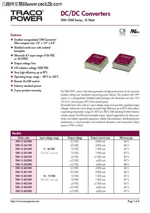
DC/DC ConvertersTHN 15WI Series, 15 WattFeatures◆ Smallest encapsulated 15W Converter!Ultra compact size: 1.0” x 1.0” x 0.4”◆ Shielded metal case with isolatedbaseplate◆ Ultrawide 4:1 input ranges 9-36 VDCor 18-75VDC◆ Output voltage Trim◆ I/O isolation voltage 1500 VDC◆ Very high efficiency up to 87%◆ Operating temp. range : –40°C to +85°C◆ Remote On/Off control◆ Industry standard pinout◆ 3-year product warranty The THN-15WI series is the latest generation of high performance dc-dc convertermodules setting new standards concerning power density. This product with 15Wcomes in a encapsulated, shielded metal package with dimensions of only 1.0”x1.0”x 0.4” and occupies 50% (!) less board space.All models have ultra wide 4:1 input voltage range and precisely regulated outputvoltages. Advanced circuit design provides high efficiency up to 87% which allowsa operating temperature range of –40°C to +85°C (with derating) Further featuresinclude remote On/Off and trimmable output. Typical applications for these con-verters are battery operated equipment, mobile instrumentation, distributed powerarchitectures in communication and industrial electronics and everywhere wherespace on PCB is critical.C B Scheme UL 60950-1UL 60950-1Input SpecificationsInput current at no load 24 Vin; 3.3 VDC models:50 mA typ.24 Vin; 5 VDC models:70 mA typ..24 Vin; other models:20 mA typ.48 Vin; 3.3 & 5 VDC models:40 mA typ.48 Vin; other models:15 mA typ.Input current at full load 24 Vin; 3.3 VDC models:690 mA typ.24 Vin; other models:770 mA typ..48 Vin; 3.3 VDC models:340 mA typ.48 Vin; other models:380 mA typ.Start-up voltage / 24 Vin models:9 VDC /8 VDCunder voltage shut down 48 Vin models:18 VDC /16 VDCSurge voltage 24 Vin models:50 V max.(100 msec. max.)48 Vin models:100 V max.Reflected input ripple current 30 mA typ.Conducted noise (input)EN 55022 level A, FCC part 15, level Awith external capacitorsee application note.Output SpecificationsVoltage set accuracy ±1 %Output voltage adj. range ±10 % only for single output models.see application note.Regulation – Input variation (Vmin – Vmax)single output models:0.2 % max.dual output models:0.5 % max.– Load variation (0 – 100 %) single output models:0.2 % max.dual output models balanced load: 1.0 % max.dual output models unbalanced load (25% /100%): 5.0 % max.Minimum load not requiredRipple and noise (20 MHz bandwidth)100 mVpk-pk max. with external capacitorsee application note.Temperature coefficient ±0.02 %/KOutput current limitation at 150 % of Iout max., foldbackShort circuit protection indefinite (automatic recovery)Over voltage protection 3.3 VDC models: 3.7 – 5.4 Vout5 VDC models: 5.6 – 7.0 Vout12 VDC models:13.5 – 19.6 Vout15 VDC models:16.8 – 20.5 VoutStart up time (nominal Vin and constant resistive load)30 ms typ. (for power on and remote on) Transient response setting time (25% load step change)250 µs typ.Max. capacitive load 3.3 VDC models: 12’000µF5 VDC models:6’000 µF12 VDC models:1’000 µF15 VDC models:660 µF±5 VDC models:±3’000 µF±12 VDC models:±520 µF±15 VDC models:±330 µFGeneral SpecificationsTemperature ranges – Operating–40°C to +85°C (with derating)– Casing+105°C max.– Storage–55°C to +125°CPower derating 2.2 %/K above 60°CThermal impedance – Natural convection 18.2°C/W– Natural convection with heat-sink 15.8°C/WHumidity (non condensing) 5 % to 95 % rel H max.Reliability, calculated MTBF (MIL-HDBK-217F, at +25°C, ground benign)>560’000 hIsolation voltage (60 sec.)– Input/Output1’600 VDCIsolation capacitance – Input/Output 1000 pF typ.Isolation resistance– Input/Output (500 VDC)>1’000 MOhmRemote On/Off – On: 3.0 ... 15 VDC or open circuit– Off:0 ... 1.2 VDC or short circuit pin 6 and pin 2– Off idle current: 2.5 mASwitching frequency (fixed) 400 kHz typ. (pulse width modulation PWM) Vibration and thermal shock MIL-STD-810FSafety standards UL/cUL 60950-1, EN 60950-1, IEC 60950-1 Safety approvals – CB test report (IEC 60950-1)/products/thn15wi-cb.pdf – UL/cUL -> certifications -> File e188913 Environmental compliance – Reach /products/thn15wi-reach.pdf – RoHS RoHS directive 2011/65/EUPhysical SpecificationsCasing material nickel coated copperBaseplate non conductive FR4Potting material epoxy (UL 94V-0 rated)Weight 15 g (0.53 oz)Soldering temperature max. 265°C / 10sec.Application note: /products/thn15wi-application.pdfOutline Dimensions mm (inches)Dimensions in [mm], () = Inch Pin diameter ø 1.0 (0.04)Pin pitch tolerances: ±0.25 (±0.01)Tolerances: ±0.5 (±0.02)Note:The product label on converter has to be re-moved before mounting the heat-sink.For volume orders converters will be sup-plied with heat-sink already mounted. Please contact factory for quotation.Separate heat-sinks are only available for prototypes and small quantity orders.Order code: THN-HS1(cont.: heat-sink, thermal pad, 2 clamps)Material: AluminumFinish: Anodic treatment (black)Weight: 8 g (0.28 oz) without converterThermal impedance after assembling: 15.8 K/W Heat-Sink (Option)31.0 (1.22)max.14.5 (0.57) 16.5 (0.65) max.ConverterHeat-sink Thermal pad Clamp Dimensions in mm, () = Inch*Optional versions:• without remote and trim pins add suffix -B (e.g.TEN 25-2412WI-B)• without remote pin add suffix -B1 (e.g. TEN 25-2413WI-B1)• without trim pin add suffix -B2 (e.g. TEN-25-4811WI-B2)。
TRACO电源使用说明Industrial Power SuppliesTIS Series 50 - 600 WattInput SpecificationsInput voltage range– TIS 5093 – 264 VAC– TIS 75,150, 300, 60093 – 132 VAC / 187 – 264 VAC– TIS 500-124-230187 – 264 VAC– TIS 500-124-11593 – 132 VACInput frequency47 – 63 HzInput current at full load (typ.)115 VAC230 VAC– TIS 50 1.2 A 0.7 A– TIS 75 1.7 A0.9 A– TIS 150 3.0 A 1.7 A– TIS 300 5.4 A 3.3 A– TIS 5009.5 A 5.5 A– TIS 60010.5 A 6.4 ARecommended circuit breaker,– TIS 50 5.0 A characteristic C– TIS 75 5.0 Aor fuse, slow blow typ– TIS 15010.0 A– TIS 30015.0 A– TIS 50015.0 A– TIS 60020.0 AOutput SpecificationsOutput voltage adj. range– 12 VDC models12 – 14 VDC – 24 VDC models24 – 28 VDC– 28 VDC models28 – 32 VDC– 48 VDC models48 – 52 VDC (48 – 55 VDC on request))– 72 VDC models60 – 76 VDCRegulation–Input variation± 0.2 %– Load variation (10–90%)–TIS 50, TIS 75, TIS 150± 1.0 %–TIS 300, TIS 500, TIS 600± 0.3 %(± 2.0 % in par allel operation)Ripple and Noise (20MHz Bandwidth)< 50 mV pk-pkElectronic short circuit protection current limitation at 110 % typ.(constant current, automatic restart)Overvoltage protection, triggerpoint at140 % typ. Vout nom.Hold-up time115 VAC230 VAC– TIS 50 ... TIS 300min. 25 ms min. 30 ms– TIS 500min. 20 ms min. 40 ms– TIS 600min. 15 ms min. 25 msGeneral SpecificationsTemperature ranges–Operating (ambient temp.)–25 °C…+70 °C (–13°F...+185°F)–Derating above 50 °C (122°F) 2% / K–Storage (non operating)–25 °C…+85 °C(–13°F...+185°F) Humidity (non condensing)95 % rel H max.Pollution degree2Temperature coefficient0.02 % / KSwitching frequency80 kHz typ. (Pulswidth modulation)Efficiency– TIS 50 ... TIS 30085 % typ.– TIS 50090 % typ.– TIS 60090 % typ.Isolation according to IEC/ EN 60950, UL 60950, UL 508 Reliability, calculated MTBF (MIL-HDBK-217 E)– TIS 50 /75450000 h @ +25°C/ 420000 h @ +25°C–TIS 150 /300420000 h @ +25°C/ 360000 h @ +25°C–TIS 500 /600340000 h @ +25°C/ 300000 h @ +25°CSafety standards IEC/ EN 60950 (SELV, except 72 VDC models),UL/cUL 60950, UL 508, UL/cUL 1604Safety approvals UL/cUL 60950 recognized, File E181381(TIS 500 pending)UL/cUL 508 listed, File E210002(tested by UL to surrounding temperature of 40°C)*UL/cUL 1604 listed, File E213613 (Class I,Division 2, Groups A, B, C and D hazardous locations) *basic models except TIS50 & TIS500CB-Report as per IEC 60950 Electromagnetic compatibility (EMC), Emissions EN 50081-1 / EN 50081-2– Conducted RI suppression on input EN 55011 class B, EN 55022 class B,FCC part 15, level B– Radiated RI suppression EN 55011 class A, EN 55022 class A,FCC part 15, level A– Harmonic current emissions (for -P models)EN 6100-3-2, class AElectromagnetic compatibility (EMC), Immunity EN 50082-2 – Electrostatic discharge (ESD)IEC / EN 61000-4-2 4 kV / 8 kV – Radiated RF field immunity IEC / EN 61000-4-310 V / m– Electrical fast transient / burst immunity IEC / EN 61000-4-4 2 kV– Surge immunity IEC / EN 61000-4-5 2 kV / 4 kV– Immunity to conducted RF disturbances IEC / EN 61000-4-610 V– Power frequency field immunity IEC / EN 61000-4-830 A /mSafety class Degree of electrical protection 1 (IEC 536)Case protection IP 20 (IEC 529)Environment–Vibration IEC 60068-2-6;1 gn, 200 sweeps, each axis – Shock IEC 60068-2-27; 15 gn, 11 ms, each axis Enclosure material Aluminium (chassis) / zinc plated steel (cover)Mounting (snap-on with selflocking spring)for 35 mm DIN-rails as per EN 50022Connection Plugable screw terminals (plugs included)(TIS 600: screw terminal blocks)Rev. 01/04。
多合一控制器电源模块的选择及检测方法概述:随着科技的不断发展和进步,多合一控制器在各个行业中得到了广泛的应用。
而电源模块作为多合一控制器的重要组成部分,对于控制器的性能和可靠性有着至关重要的影响。
因此,选择合适的电源模块以及合理的检测方法对于多合一控制器的正常运作至关重要。
本文将就多合一控制器电源模块的选择以及检测方法进行论述和分析。
一、电源模块的选择多合一控制器电源模块的选择是确保多合一控制器正常运行的首要任务。
下面将从功率需求和稳定性两个方面来介绍电源模块的选择要点。
1. 功率需求在选择电源模块时,首先需要确定多合一控制器的功率需求。
通过评估控制器的所有功能板和芯片组的功耗,计算所需的总功率。
然后根据实际需求,选择具有对应功率输出的电源模块。
需要注意的是,应该给电源模块设置一定的额定功率储备,以应对电源模块在运行过程中可能出现的功率峰值。
2. 稳定性稳定性是多合一控制器电源模块选择的另一个重要指标。
为了确保电源模块在工作过程中的稳定性,需要考虑以下几个因素:(1)电源模块的输出电压稳定性:稳定的输出电压对于多合一控制器的正常运行至关重要。
因此,在选择电源模块时,需要关注其输出电压的稳定性指标。
(2)电源模块的输出电流能力:根据多合一控制器的实际功率需求以及各个功能模块的工作电流,选择具有足够输出电流能力的电源模块。
(3)过载和短路保护功能:考虑到多合一控制器在使用过程中可能会遇到的过载和短路情况,选择带有过载和短路保护功能的电源模块。
这样可以有效地保护控制器和其他电子元件的安全。
二、电源模块的检测方法为了确保多合一控制器电源模块的可靠性和安全性,需要进行一系列的检测。
下面将介绍几种常用的电源模块检测方法。
1. 输出电压测试输出电压是电源模块的核心参数,也是评估其性能的重要指标。
可以通过使用万用表或示波器,将其接入电源模块的输出端口,测量输出电压的稳定性和准确性。
测试时应考虑最大负载条件下的输出电压情况,并确保其在可接受范围内。
怎么选择购买的电脑配件电源模块电脑配件中的电源模块是确保电脑正常运行的重要组件之一。
在选择购买电脑配件电源模块时,需要考虑多方面因素,以确保选择到适合自己需求的产品。
功率需求首先要考虑的是电源模块的功率需求。
根据电脑配置的不同,功率需求也会有所差异。
确保选择的电源模块功率能够满足电脑运行的需求,同时留有一定的冗余以应对突发情况。
效率等级电源模块的效率等级是衡量其能源利用效率的重要标准。
通常分为铜牌、银牌、金牌和白金等级。
选择效率高的电源模块不仅可以节省能源,还能减少电脑发热,延长硬件寿命。
稳定性与品质稳定的电源供应对电脑硬件的保护至关重要。
优质的电源模块通常采用高品质元件和稳定的电路设计,能够提供稳定的电压输出,减少硬件损坏的风险。
接口和线缆考虑到电脑内部的布线和接口情况,选择具有足够接口和线缆长度的电源模块可以更好地满足电脑的连接需求,避免出现布线混乱或连接不当的情况。
散热性能良好的散热性能可以确保电源模块长时间稳定运行而不过热。
选择带有有效散热设计的电源模块可以提高整机稳定性,减少硬件损坏风险。
价格与品牌最后要考虑的是价格与品牌。
不同品牌的电源模块在性能和质量上会有所差异,根据自身预算和信任度选择适合的产品。
选购电脑配件电源模块时需要考虑功率需求、效率等级、稳定性与品质、接口和线缆、散热性能以及价格与品牌等因素。
只有综合考虑这些方面,才能选择到适合自己电脑的电源模块。
在选购电脑配件电源模块时,需综合考虑功率需求、效率等级、稳定性与品质、接口和线缆、散热性能以及价格与品牌等多个方面,以确保选择到适合自己需求的产品,提高电脑的稳定性和性能表现。
小体积5W系列产品特性■小体积封装37*25*20mm■内置EMC电路■输入电压范围85-265VAC/100-370VDC■工作温度范围:-40~70℃(根据技术手册中的输出负载降额曲线使用)■隔离电压:3000VAC■低空载损耗,高效率,绿色环保■具有输出短路、过流、过压等保护功能■符合EN55032等相关标准封装尺寸小体积7W系列产品特性■小体积封装37*28*20mm■内置EMC电路■输入电压范围85-265VAC/100-370VDC■工作温度范围:-40~70℃(根据技术手册中的输出负载降额曲线使用)■隔离电压:3000VAC■低空载损耗,高效率,绿色环保■具有输出短路、过流、过压等保护功能■符合EN55032等相关标准封装尺寸产品特性■小体积封装27*37*17mm■输入电压范围85-265VAC/100-370VDC■工作温度范围:-40~70℃(根据技术手册中的输出负载降额曲线使用)■隔离电压:3000VAC■低空载损耗,高效率,绿色环保■具有输出短路、过流、过压等保护功能封装尺寸产品特性■小体积封装25.5*39.5*22mm■输入电压范围85-265VAC/100-370VDC■工作温度范围:-40~70℃(根据技术手册中的输出负载降额曲线使用)■隔离电压:3000VAC■低空载损耗,高效率,绿色环保■具有输出短路、过流、过压等保护功能封装尺寸产品特性■小体积封装36*48*23mm■输入电压范围85-265VAC/100-370VDC■工作温度范围:-40~70℃(根据技术手册中的输出负载降额曲线使用)■隔离电压:3000VAC■低空载损耗,高效率,绿色环保■具有输出短路、过流、过压等保护功能封装尺寸产品特性■小体积封装36*48*23mm■输入电压范围85-265VAC/100-370VDC■工作温度范围:-40~70℃(根据技术手册中的输出负载降额曲线使用)■隔离电压:3000VAC■低空载损耗,高效率,绿色环保■具有输出短路、过流、过压等保护功能封装尺寸三线四相24W单路系列产品特性■小体积封装25.5*39.5*22mm■输入电压范围85-450VAC/100-630VDC■工作温度范围:-40~70℃(根据技术手册中的输出负载降额曲线使用)■隔离电压:3000VAC■低空载损耗,高效率,绿色环保■具有输出短路、过流、过压等保护功能封装尺寸24W正负双路输出系列产品特性■小体积封装25.5*39.5*22mm■输入电压范围85-265VAC/100-370VDC■工作温度范围:-40~70℃(根据技术手册中的输出负载降额曲线使用)■隔离电压:3000VAC■低空载损耗,高效率,绿色环保■具有输出短路、过流、过压等保护功能封装尺寸。