From Simulink model to DLL
- 格式:pdf
- 大小:99.64 KB
- 文档页数:15

simulink转化为model reference -回复Simulink is a powerful tool for modeling and simulating dynamic systems. It offers a variety of features that allow users to design and analyze complex systems in a graphical environment. However, as systems become more intricate, managing the Simulink models can become challenging. This is where model reference comes into play.Model reference is a feature in Simulink that enables the modularization and hierarchical organization of Simulink models. It allows users to divide a large, complex system into smaller, more manageable components called referenced models. These referenced models can be reused, shared, and integrated into larger systems, providing an efficient way to handle complex designs.To convert a Simulink model into a model reference, follow these steps:Step 1: Identifying modular componentsThe first step is to identify parts of the Simulink model that can be modularized. These components should have clear inputs andoutputs and perform a specific function. It is important to ensure that the components are decoupled from each other to allow for independent development and testing.Step 2: Creating referenced modelsOnce the modular components have been identified, create a new Simulink model for each component. This model will serve as the referenced model. Copy or move the necessary blocks from the original model into each referenced model, ensuring that all the required connections are maintained.Step 3: Defining inputs and outputsIn the referenced model, define input and output ports to allow for interaction with other components. Inputs represent signals or data that flow into the referenced model, while outputs represent signals or data that flow out of the referenced model. These ports act as interfaces to connect the referenced model with other parts of the system.Step 4: Creating a top-level modelNext, create a new Simulink model that will serve as the top-level model. This model will act as the container for the referencedmodels. Add the referenced models as subsystem blocks in the top-level model and connect them using the input and output ports defined in the referenced models.Step 5: Parameterizing the referenced modelsTo make the referenced models reusable, it is important to parameterize them. Parameters can be added to the referenced models to allow users to customize the behavior of the models without modifying the model structure itself. This enhances reusability and flexibility.Step 6: Testing and simulationOnce the model reference hierarchy is established, it is crucial to test and simulate the system to ensure that the components interact correctly. Verify that the inputs and outputs are correctly connected, and the system functions as expected. Simulate the system with various test cases to validate its behavior and performance.Step 7: Managing and updating the referenced modelsAs the system evolves, it is necessary to manage and update the referenced models. Any changes made to a referenced model willpropagate to all instances of that model in the top-level model. This ensures consistency and eliminates the need to modify individual instances separately.In conclusion, converting a Simulink model into a model reference hierarchy provides an efficient way to manage complex systems. By modularizing the system into referenced models, it becomes easier to develop, maintain, and reuse different components. Thestep-by-step process outlined above enables users to effectively convert a Simulink model into a model reference structure, enhancing the scalability and reusability of their designs.。
Simulink转与LabVIEW、Veristand调用的DLL、OUT文件1.在软件安装过程中先安装MATLAB,simulink,simulinkcoder,embedded coder等组件,不同的序列号有不同的模块,可以自定义选择;simulink coder与embedded coder即是以前版本的real-time workshop。
MATLAB的位数应该与LabVIEW的位数保持一致,否则可能会导致Veristand不能与simulink对接。
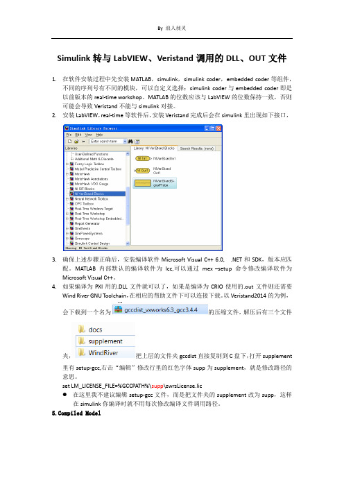
2.安装LabVIEW,real-time等软件后,安装Veristand完成后会在simulink里出现如下接口,3.确保上述步骤正确后,安装编译软件Microsoft Visual C++ 6.0, .NET和SDK,版本应匹配。
MATLAB内部默认的编译软件为lcc,可以通过mex –setup命令修改编译软件为Microsoft Visual C++。
4.如果编译为PXI用的.DLL文件就可以了,如果是编译为CRIO使用的.out文件则还需要Wind River GNU Toolchain,在相应的帮助文件下可以连接下载。
以Veristand2014的为例,会下载到一个名为的压缩文件,解压后有三个文件夹,把上层的文件夹gccdist直接复制到C盘下,打开supplement里有setup-gcc,右击“编辑”修改行里的红色字体supp为supplement,就是修改路径的意思。
set LM_LICENSE_FILE=%GCCPATH%\supp\zwrsLicense.lic在这里我不建议编辑setup-gcc文件,而是把文件夹的supplement改为supp,这样在simulink你编译时就不用每次修改编译文件调用路径。
piled ModelAfter you have the correct compiler set up and selected, complete the following steps to build the compiled model in the Real-Time Workshop software:unch the Simulink software and load your model you want toconvert.2.Select Simulation»Configuration Parameters to launch theConfiguration Parameters dialog box.3.Click the Solver tab and configure the following options:o Stop time: info Type: Fixed-step4.Click the Real-Time Workshop tab.5.Click the Browse button to launch the System Target File Browserdialog box.6.Select the correct option for your target from the list:o(Windows, Phar Lap ETS) NIVeriStand.tlc—NI Real-Time Targeto(VxWorks) NIVeriStand VxWorks.tlc—NI Real-Time TargetNote If the appropriate .tlc is not visible, the MATLABsoftware files might be read-only, and NI VeriStand is not ableto provide this option. To display the option, add thefollowing lines to the matlabrc.m file, a file that isinstalled by the MATLAB software:addpath('X:\VeriStand');NIVeriStandAddPaths;编译完成后,Matlab的Command Windows中出现下列提示### Successful completion of Real-Time Workshop build procedure for model:ModelName### Generating code into build folder: C:\Users\LabVIEW\Documents\MATLAB\engine_niVeriStand_rtwWarning: Signal logging is not supported when MAT-file logging is enabled. When your model code executes, thesignal logging variable 'rt_sldemo_engine_output' will not be saved to the MAT-file. (To suppress this warning,disable signal logging for your model)### Generated code for 'engine' is up to date because no structural, parameter or codereplacement library changes were found.### NI VeriStand code generation started### NI VeriStand code generation done.### Processing Template Makefile: D:\VeriStand\2014\ModelInterface\tmw\R2007b\NIVeriStand_vc.tmfNI VeriStand ==> Using the Microsoft Visual C++ 10.0 tools.### engine.mk which is generated from D:\VeriStand\2014\ModelInterface\tmw\R2007b\NIVeriStand_vc.tmf is up to date### Building engine: .\engine_vc.batC:\Users\LabVIEW\Documents\MATLAB\engine_niVeriStand_rtw>set MATLAB=D:\Program Files\MATLAB\R2012bC:\Users\LabVIEW\Documents\MATLAB\engine_niVeriStand_rtw>set VCINSTALLDIR=C:\Program Files\Microsoft Visual Studio 10.0\VC\C:\Users\LabVIEW\Documents\MATLAB\engine_niVeriStand_rtw>call"D:\VeriStand\2014\ModelInterface\tmw\toolchain\nivs_vcvars32_100.bat"Setting environment for using Microsoft Visual Studio 2010 x86 tools.C:\Users\LabVIEW\Documents\MATLAB\engine_niVeriStand_rtw>cd /d C:\Users\LabVIEW\Documents\MATLAB\engine_niVeriStand_rtw\C:\Users\LabVIEW\Documents\MATLAB\engine_niVeriStand_rtw>nmake -f engine.mk GENERATE_REPORT=0 NIDEBUG=0 NIOPT="Default" OPTS="" /IMicrosoft (R) 程序维护实用工具10.00.30319.01 版版权所有(C) Microsoft Corporation。

MarlabSimulink(2014a)生成C++代码,并用VC2010生成dll供VBA或VB调用使用说明一、过程概述1、使用VC2010生成.dll文件,测试VC程序是否正常2、使用VBA调用VC2010生成的.dll文件,测试.dll文件调用的VBA代码是否正常,这里使用Excel VBA主要是为了以后输入输出数据更方便。
3、使用MatlabSimulink模型编译成c++文件。
4、VC2010集成MatlabSimulink生成的c++代码,验证在VC2010环境下能正常运行。
5、VC2010将生成的程序编译成.dll文件,以便于VB调用6、使用步骤1,2验证MatlabSimulink生成的代码二、具体实施过程描述1、使用VC2010生成.dll文件1.1工程建立首先打开VS 2010--> 新建工程 --> Win32 --> Win32项目 --> 输入工程名称(MakeDll),选择好保存工程的路径-->确定。
在弹出的“应用程序设置”--> "应用成程序型" --> 选择 "DLL(D)" --> 附加选项-> 选择"空项目(E)" ---->点击"完成"进入项目工作窗口1.2开始创建DLL第一步:在头"解决方案资源管理器" --> 头文件 --> 右键 -->添加新建项---→选择"头文件(.h)" -->输入文件名称(max) --> 点击“添加(A)”,完成max.h文件的添加。
max.h头文件中的代码为:1. #ifndef _MAX_H2. #define _MAX_H_3. __declspec(dllexport) int __stdcall fmax(int a,int b);4. #endif代码说明:__declspec(dllexport) 的作用是指定导出该函数为DLL函数;__stdcall是函数调用约定,表示该DLL函数被C/C++以外的语言调用;备注:使用时需要根据实际定义的主函数返回值类型和函数名称修改低3行红色而自体标记部分内容。


Simulink转与LabVIEWveristand的DLL及out⽂件Simulink转与LabVIEW、Veristand调⽤的DLL、OUT⽂件1.在软件安装过程中先安装MATLAB,simulink,simulinkcoder,embedded coder等组件,不同的序列号有不同的模块,可以⾃定义选择;simulink coder与embedded coder即是以前版本的real-time workshop。
MATLAB的位数应该与LabVIEW的位数保持⼀致,否则可能会导致Veristand不能与simulink对接。
2.安装LabVIEW,real-time等软件后,安装Veristand完成后会在simulink⾥出现如下接⼝,3.确保上述步骤正确后,安装编译软件Microsoft Visual C++ 6.0, .NET和SDK,版本应匹配。
MATLAB内部默认的编译软件为lcc,可以通过mex –setup命令修改编译软件为Microsoft Visual C++。
4.如果编译为PXI⽤的.DLL⽂件就可以了,如果是编译为CRIO使⽤的.out⽂件则还需要Wind River GNU Toolchain,在相应的帮助⽂件下可以连接下载。
以Veristand2014的为例,会下载到⼀个名为的压缩⽂件,解压后有三个⽂件夹,把上层的⽂件夹gccdist直接复制到C盘下,打开supplement⾥有setup-gcc,右击“编辑”修改⾏⾥的红⾊字体supp为supplement,就是修改路径的意思。
set LM_LICENSE_FILE=%GCCPATH%\supp\zwrsLicense.lic在这⾥我不建议编辑setup-gcc⽂件,⽽是把⽂件夹的supplement改为supp,这样在simulink你编译时就不⽤每次修改编译⽂件调⽤路径。
/doc/3ac451485022aaea988f0f0d.html piled ModelAfter you have the correct compiler set up and selected, complete the following steps to build the compiled model in the Real-Time Workshop software:/doc/3ac451485022aaea988f0f0d.html unch the Simulink software and load your model you want to convert.2.Select Simulation?Configuration Parameters to launch theConfiguration Parameters dialog box.3.Click the Solver tab and configure the following options:o Stop time: info Type: Fixed-step4.Click the Real-Time Workshop tab.5.Click the Browse button to launch the System Target File Browserdialog box.6.Select the correct option for your target from the list:o(Windows, Phar Lap ETS) NIVeriStand.tlc—NI Real-Time Targeto(VxWorks) NIVeriStand VxWorks.tlc—NI Real-Time TargetNote If the appropriate .tlc is not visible, the MATLABsoftware files might be read-only, and NI VeriStand is not ableto provide this option. To display the option, add thefollowing lines to the matlabrc.m file, a file that isinstalled by the MATLAB software:addpath('X:\VeriStand');NIVeriStandAddPaths;编译完成后,Matlab的Command Windows中出现下列提⽰### Successful completion of Real-Time Workshop build procedure for model:ModelName### Generating code into build folder: C:\Users\LabVIEW\Documents\MATLAB\engine_niVeriStand_rtwWarning: Signal logging is not supported when MAT-file logging is enabled. When your model code executes, thesignal logging variable 'rt_sldemo_engine_output' will not be saved to the MAT-file. (To suppress this warning,disable signal logging for your model)### Generated code for 'engine' is up to date because no structural, parameter or codereplacement library changes were found.### NI VeriStand code generation started### NI VeriStand code generation done.### Processing Template Makefile: D:\VeriStand\2014\ModelInterface\tmw\R2007b\NIVeriStand_vc.tmfNI VeriStand ==> Using the Microsoft Visual C++ 10.0 tools.### engine.mk which is generated from D:\VeriStand\2014\ModelInterface\tmw\R2007b\NIVeriStand_vc.tmf is up to date ### Building engine: .\engine_vc.batC:\Users\LabVIEW\Documents\MATLAB\engine_niVeriStand_rtw>set MATLAB=D:\Program Files\MATLAB\R2012bC:\Users\LabVIEW\Documents\MATLAB\engine_niVeriStand_rtw>set VCINSTALLDIR=C:\Program Files\Microsoft Visual Studio 10.0\VC\C:\Users\LabVIEW\Documents\MATLAB\engine_niVeriStand_rtw>call"D:\VeriStand\2014\ModelInterface\tmw\toolchain\nivs_vcvars32_100.bat"Setting environment for using Microsoft Visual Studio 2010 x86 tools.C:\Users\LabVIEW\Documents\MATLAB\engine_niVeriStand_rtw>cd /dC:\Users\LabVIEW\Documents\MATLAB\engine_niVeriStand_rtw\C:\Users\LabVIEW\Documents\MATLAB\engine_niVeriStand_rtw>nmake -f engine.mk GENERATE_REPORT=0 NIDEBUG=0 NIOPT="Default" OPTS="" /IMicrosoft (R) 程序维护实⽤⼯具10.00.30319.01 版版权所有(C) Microsoft Corporation。

simulink模型引用Simulink模型引用是Simulink中非常常见和重要的功能。
它可以帮助用户快速构建复杂的模型,并且能够减少模型参数的修改和维护的难度。
下面将分步骤详细介绍如何使用Simulink模型引用。
1. 创建一个新模型首先,需要创建一个新模型,用于存储所有被引用的模型。
这个模型可以命名为主模型。
主模型中的模块将会表示对其他模型的引用。
2. 创建需要被引用的模型现在,可以创建需要被引用的模型。
这些模型可以是原始模型的一部分,或者是完全独立于主模型的模型。
请注意,在创建子模型时,应该将这些模型存储在一起,并使用描述性名称进行命名。
3. 在主模型中添加模型引用接下来,在主模型中添加需要被引用的子模型。
要添加一个模型引用,可以使用“Subsystem”或“Model Block”块。
这些块可以在Simulink库浏览器中查找和添加。
4. 配置模型引用参数添加模型引用后,需要配置模型引用的参数。
参数包括子模型的路径和名称。
子模型的路径可以是相对路径或绝对路径。
子模型的名称是在子模型中指定的名称。
5. 添加端口由于子模型被引用为一个单一的块,因此必须添加输入和输出端口以与主模型交互。
这可以通过单击“Subsystem”或“Model Block”块并选择“Add ports”来完成。
然后,您可以选择是要在输入端口上提供信号还是要在输出端口上提取信号。
6. 连接端口在指定每个端口的输入和输出信号之后,将所有端口连接起来以确保正确的信号流。
这可以通过在每个端口之间拖动线条来完成。
完成连接后,模型引用已经设置完成。
总之,使用Simulink模型引用可以大大简化模型的构建过程,并减少重复工作,使模型变得更加清晰,并提高模型的可维护性。
除此之外,模型引用还可以促进模型的模块化设计,提高工作效率和准确性。
Simulink 快速入门要构建模型, 可以使用Simulink® Editor 和Library Browser。
启动 MATLAB 软件启动 Simulink 之前, 请先启动MATLAB®。
请参阅启动和关闭(MATLAB)。
配置 MATLAB 以启动 Simulink您在 MATLAB 会话中打开第一个模型时需要的时间比打开后续模型长, 因为默认情况下, MATLAB 会在打开第一个模型时启动 Simulink。
这种即时启动Simulink 的方法可以缩短 MATLAB 启动时间, 避免不必要的系统内存占用。
•要快速打开第一个模型, 您可以配置 MATLAB, 在它启动时同时启动Simulink。
要启动 Simulink 而不打开模型或 Library Browser, 请使用start_simulink。
•根据 MATLAB 的启动方式, 恰当使用此命令:•在 MATLAB startup.m文件中在操作系统命令行中, 使用matlab 命令和-r 开关例如, 要在运行Microsoft®Windows®操作系统的计算机上启动 MATLAB 时启动 Simulink, 请创建具有以下目标的桌面快捷方式:matlabroot\bin\win64\matlab.exe -r start_simulink在 Macintosh 和Linux®计算机上, 可在启动 MATLAB 时使用以下命令启动Simulink 软件:matlab -r start_simulink打开 Simulink Editor•要打开 Simulink Editor, 您可以:•创建一个模型。
在 MATLAB 的Home 选项卡上, 点击Simulink 并选择一个模型模板。
或者, 如果您已经打开了 Library Browser, 请点击New Model 按钮/。
有关创建模型的其他方法, 请参阅创建模型。
代码中调用simulink模型在代码中调用Simulink模型,通常使用以下语法:```MATLAB(t, x, y) = sim(model, timespan, options, ut)```其中,各参数含义如下:- `model`:需要进行仿真的系统模型框图名称。
- `timespan`:系统仿真的时间范围(起始至终止时间),可有如下形式:- `tFinal`:设置仿真终止时间。
仿真起始时间默认为0。
- `(tStart, tFinal)`:设置起始时间(tStart)与终止时间(tFinal)。
- `(tStart, OutputTimes, tFinal)`:设置起始时间(tStart)与终止时间(tFinal),并且设置仿真返回的时间向量(tStart, OutputTimes, tFinal),其中tStart、OutputTimes、tFinal必须按照升序排列。
- `options`:由`simset`命令所设置的除仿真时间外的仿真参数。
- `ut`:表示系统模型顶层的外部可选输入。
ut可以是MATLAB函数。
可以使用多个外部输入ut1、ut2、...。
- `t`:返回系统仿真的时间向量。
- `x`:返回系统仿真的状态变量矩阵。
- `y`:返回系统仿真的输出矩阵。
按照顶层输出Outport模块的顺序输出。
如果输出信号为向量输出,则输出信号具有与此向量相同的维数。
你可以根据实际情况设置不同的参数,以实现对Simulink模型的调用和仿真。
如果你需要更多关于调用Simulink模型的信息,请提供更多细节,以便我更好地为你解答。
Simulink中的Goto和From用法1. 简介Simulink是一种用于建模、仿真和分析动态系统的工具。
在Simulink中,Goto和From是两个非常重要的块,用于在模型中实现信号传递和跳转。
Goto块用于标识信号的发送位置,而From块用于接收来自Goto块的信号。
这两个块通常一起使用,以实现模块之间的数据传递和控制流。
在本文中,我们将详细介绍Goto和From块的用法,包括如何使用它们在Simulink模型中传递信号和控制流。
2. Goto块的用法Goto块用于标识信号的发送位置。
它允许您将信号发送到模型中的其他位置,以供其他块使用。
2.1 创建Goto块要创建一个Goto块,您可以按照以下步骤操作:1.在Simulink库浏览器中找到Goto标签。
2.将Goto块拖动到模型中的所需位置。
2.2 配置Goto块创建Goto块后,您需要配置它以指定发送的信号名称。
1.双击Goto块以打开参数对话框。
2.在参数对话框中,输入所需的信号名称。
2.3 使用Goto块Goto块的使用非常简单。
只需将其连接到要发送信号的块的输出端口即可。
1.在模型中找到要发送信号的块。
2.将Goto块的输入端口连接到该块的输出端口。
2.4 示例下面是一个示例,演示了如何使用Goto块将信号发送到模型中的其他位置。
在这个示例中,我们有一个简单的Simulink模型,其中包含一个Sine Wave Generator块和一个Scope块。
我们想要将Sine Wave Generator的输出信号发送到Scope块进行可视化。
1.创建一个Goto块,并将其放置在Sine Wave Generator块的输出端口上方。
2.配置Goto块的参数,将其命名为“output”。
3.将Goto块的输入端口连接到Scope块的输入端口。
现在,当您运行模型时,Sine Wave Generator的输出信号将被发送到Scope块,您将能够在Scope块中看到信号的可视化结果。