ANSYS 中的阻尼
- 格式:pdf
- 大小:67.04 KB
- 文档页数:6
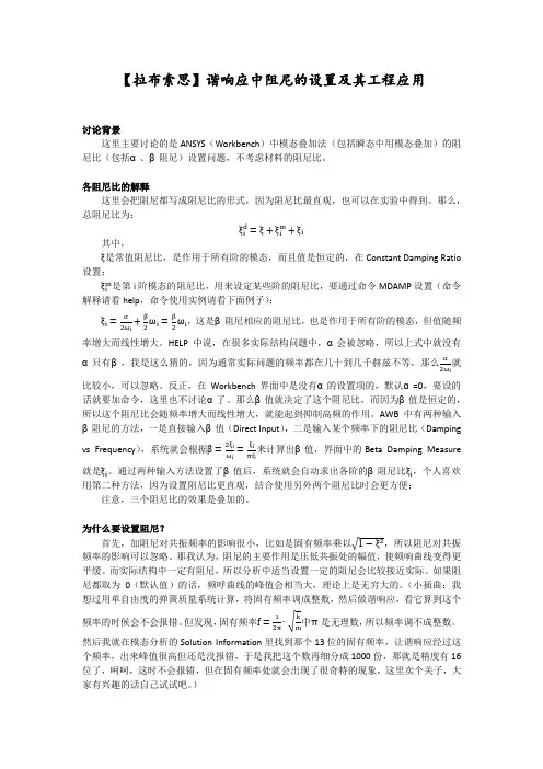
【拉布索思】谐响应中阻尼的设置及其工程应用讨论背景这里主要讨论的是ANSYS(Workbench)中模态叠加法(包括瞬态中用模态叠加)的阻尼比(包括α、β阻尼)设置问题,不考虑材料的阻尼比。
各阻尼比的解释这里会把阻尼都写成阻尼比的形式,因为阻尼比最直观,也可以在实验中得到。
那么,总阻尼比为:其中,是常值阻尼比,是作用于所有阶的模态,而且值是恒定的,在Constant Damping Ratio 设置;是第i阶模态的阻尼比,用来设定某些阶的阻尼比,要通过命令MDAMP设置(命令解释请看help,命令使用实例请看下面例子);,这是β阻尼相应的阻尼比,也是作用于所有阶的模态,但值随频率增大而线性增大。
HELP中说,在很多实际结构问题中,α会被忽略,所以上式中就没有α只有β,我是这么猜的,因为通常实际问题的频率都在几十到几千赫兹不等,那么就比较小,可以忽略。
反正,在Workbench界面中是没有α的设置项的,默认α=0,要设的话就要加命令,这里也不讨论α了。
那么β值就决定了这个阻尼比,而因为β值是恒定的,所以这个阻尼比会随频率增大而线性增大,就能起到抑制高频的作用。
AWB中有两种输入β阻尼的方法,一是直接输入β值(Direct Input),二是输入某个频率下的阻尼比(Dampingvs Frequency),系统就会根据来计算出β值,界面中的Beta Damping Measure就是。
通过两种输入方法设置了β值后,系统就会自动求出各阶的β阻尼比,个人喜欢用第二种方法,因为设置阻尼比更直观,结合使用另外两个阻尼比时会更方便;注意,三个阻尼比的效果是叠加的。
为什么要设置阻尼?首先,加阻尼对共振频率的影响很小,比如是固有频率乘以,所以阻尼对共振频率的影响可以忽略。
那我认为,阻尼的主要作用是压低共振处的幅值,使频响曲线变得更平缓。
而实际结构中一定有阻尼,所以分析中适当设置一定的阻尼会比较接近实际。
如果阻尼都取为0(默认值)的话,频呼曲线的峰值会相当大,理论上是无穷大的。
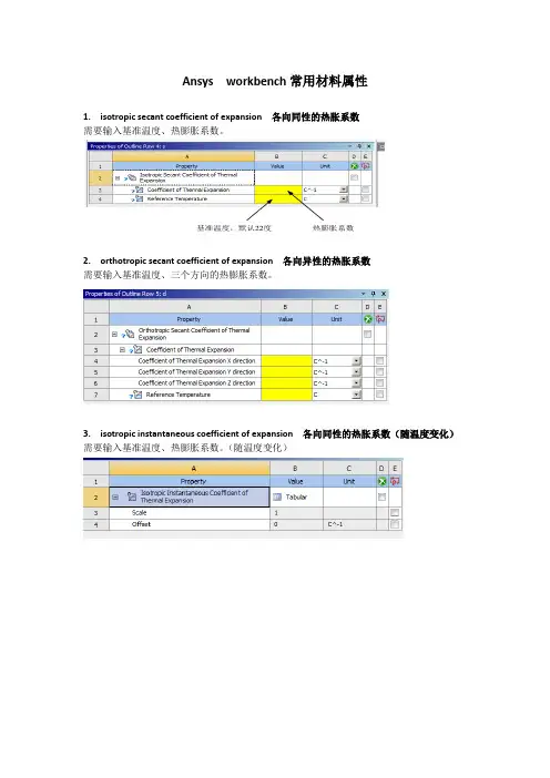
Ansys workbench常用材料属性
1. isotropic secant coefficient of expansion 各向同性的热胀系数
需要输入基准温度、热膨胀系数。
基准温度,默认22度热膨胀系数
2. orthotropic secant coefficient of expansion 各向异性的热胀系数
需要输入基准温度、三个方向的热膨胀系数。
3. isotropic instantaneous coefficient of expansion 各向同性的热胀系数(随温度变化)需要输入基准温度、热膨胀系数。
(随温度变化)
4. orthotropic instantaneous coefficient of expansion 各向异性的热胀系数(随温度变化)需要输入基准温度、三个方向的热膨胀系数。
(随温度变化)
5. 阻尼系数、质量阻尼、刚度阻尼
6.Isotropic elasticity 各项同性的线弹性材料
需要输入弹性模量与泊松比
7.orthotropic elasticity 各项异性的线弹性材料
需要输入各方向的弹性模量与泊松比
8 Bilinear isotropic/kinematic hardening 双线性材料(非线性材料)需要输入屈服强度及切向模量,需要配合isotropic elasticity使用。
9.multilinear isotropic/kinematic hardening 多线性材料(非线性材料,应力应变曲线)需要配合isotropic elasticity使用,输入应力应变曲线。
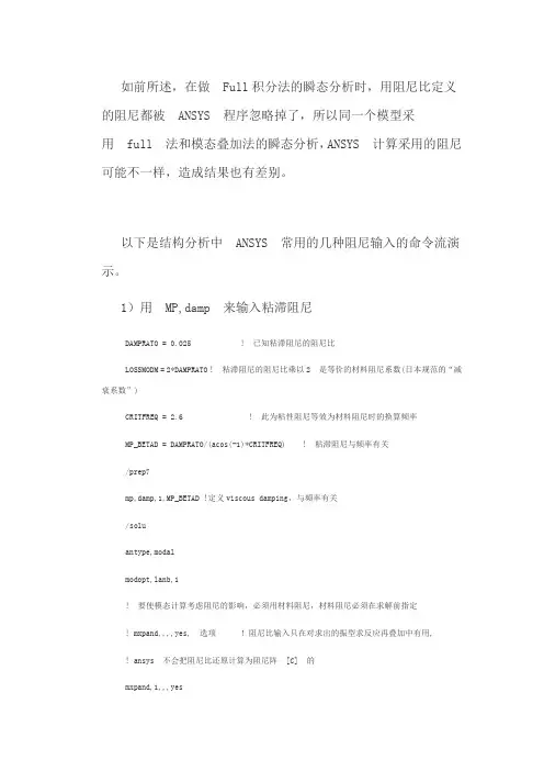
如前所述,在做 Full积分法的瞬态分析时,用阻尼比定义的阻尼都被 ANSYS 程序忽略掉了,所以同一个模型采用 full 法和模态叠加法的瞬态分析,ANSYS 计算采用的阻尼可能不一样,造成结果也有差别。
以下是结构分析中 ANSYS 常用的几种阻尼输入的命令流演示。
1)用 MP,damp 来输入粘滞阻尼DAMPRATO = 0.025 ! 已知粘滞阻尼的阻尼比LOSSMODM = 2*DAMPRATO ! 粘滞阻尼的阻尼比乘以2 是等价的材料阻尼系数(日本规范的“减衰系数”)CRITFREQ = 2.6 ! 此为粘性阻尼等效为材料阻尼时的换算频率MP_BETAD = DAMPRATO/(acos(-1)*CRITFREQ) ! 粘滞阻尼与频率有关/prep7mp,damp,1,MP_BETAD !定义viscous damping,与频率有关/soluantype,modalmodopt,lanb,1! 要使模态计算考虑阻尼的影响,必须用材料阻尼,材料阻尼必须在求解前指定! mxpand,,,,yes, 选项!阻尼比输入只在对求出的振型求反应再叠加中有用,! ansys 不会把阻尼比还原计算为阻尼阵 [C] 的mxpand,1,,,yes,,,Solve2)用 MP,Damp 输入材料阻尼DAMPRATO=0.025LOSSMODM=2*DAMPRATO ! 材料阻尼系数,书上给的一般是LOSSMODM/prep7mp,damp,1,DAMPRATO !常数,如果已知的是材料阻尼系数LOSSMODM,就要除以2 /soluantype,modal ! 使用模态叠加法modopt,lanb,1! importantmxpand,1,,,yes,,,,Solve3)用 BETAD 输入粘滞阻尼(振型叠加法)! MSUP method with BETAD! BETAD is damping_ratio/pi*f, even for MSUPDAMPRATO=0.025 ! 阻尼比LOSSMODM=2*DAMPRATO !等效的材料阻尼系数/prep7! mp,damp,1,DAMPRATOBETAD,DAMPRATO/(acos(-1)*442) ! 注意此公式! 442 是你给定的频率值/soluantype,modal !模态分析modopt,lanb,1! importantmxpand,1,,,yeslumpm,on,,,,solve/soluantype,harmic !谐分析hropt, msuphrout, on, offharfrq, FREQBEGN, FREQENDG,,,solve4)使用 DMPRAT 定义的整体结构的常数阻尼比(模态叠加法)! MSUP method with DMPRAT! shows that DMPRAT is damping ratioDAMPRATO=0.025 !全结构阻尼比是0.025LOSSMODM=2*DAMPRATO/prep7!mp,damp,1,DAMPRATO/soluantype,modal ! 先做无阻尼振型分解solve/soluantype,harmichropt,msuphrout,on,offharfrq,FREQBEGN,FREQENDGnsubst,NUM_STEPkbc,1dmprat,DAMPRATO ! 在这里定义此阻尼比,常数,,,,,,solve5)用 MP,DAMP 定义粘性阻尼做 FULL 瞬态分析! 粘性阻尼随频率增加而增加,高频衰减快! Full method with MP,DAMP! shows that MP,DAMP with FULL is damping_ratio/pi*f! As freq increases, damping is hugeDAMPRATO=0.025LOSSMODM=2*DAMPRATOCRITFREQ=480MP_BETAD=DAMPRATO/(acos(-1)*CRITFREQ) ! 注意此公式/prep7mp,damp,1,MP_BETAD6)用 DMPRAT 定义全结构常数阻尼比! Full method with DMPRATDAMPRATO=0.025LOSSMODM=2*DAMPRATOCRITFREQ=480MP_BETAD=DAMPRATO/(acos(-1)*CRITFREQ)/prep7et,1,1! mp,damp,1,MP_BETAD ! 如果用材料阻尼形式输入,就这样输入dmprat,DAMPRATO !常数阻尼比/soluantype,modal !带阻尼的振型分解modopt,lanb,3! importantmxpand,3,,,yeslumpm,on,,,solve/soluantype,harmichropt,full ! full harmonic analysis6.单元阻尼许多单元具有单元阻尼,单元阻尼都是在相关单元数据中输入。
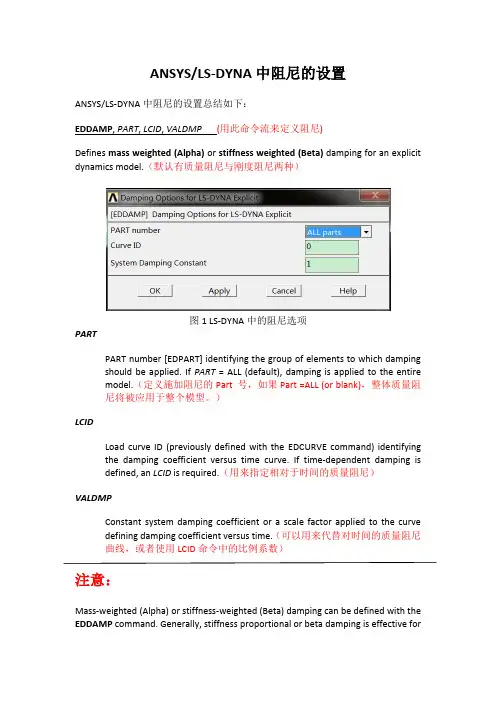
ANSYS/LS-DYNA中阻尼的设置ANSYS/LS-DYNA中阻尼的设置总结如下:EDDAMP, PART, LCID, VALDMP (用此命令流来定义阻尼)Defines mass weighted (Alpha) or stiffness weighted (Beta) damping for an explicit dynamics model.(默认有质量阻尼与刚度阻尼两种)图1 LS-DYNA中的阻尼选项PARTPART number [EDPART] identifying the group of elements to which damping should be applied. If PART = ALL (default), damping is applied to the entire model.(定义施加阻尼的Part 号,如果Part =ALL (or blank),整体质量阻尼将被应用于整个模型。
)LCIDLoad curve ID (previously defined with the EDCURVE command) identifying the damping coefficient versus time curve. If time-dependent damping is defined, an LCID is required.(用来指定相对于时间的质量阻尼)VALDMPConstant system damping coefficient or a scale factor applied to the curve defining damping coefficient versus time.(可以用来代替对时间的质量阻尼曲线,或者使用LCID命令中的比例系数)注意:Mass-weighted (Alpha) or stiffness-weighted (Beta) damping can be defined with the EDDAMP command. Generally, stiffness proportional or beta damping is effective foroscillatory motion at high frequencies. This type of damping is orthogonal to rigid body motion and so will not damp out rigid body motion. On the other hand, mass proportional or alpha damping is more effective for low frequencies and will damp out rigid body motion. The different possibilities are described below:1.Global DampingMass-weighted or Alpha damping (质量阻尼)When PART = (blank) or ALL (default), mass-weighted global damping can be defined in the following 2 ways. In this case, the same damping is applied for the entire structure.1.When the damping coefficient versus time curve (LCID) is specified usingthe EDCURVE command, VALDMP is ignored by LS-DYNA (although it iswritten in the LS-DYNA input file Jobname.K). The damping force appliedto each node in the model is given by f d= d(t)mv, where d(t) is thedamping coefficient as a function of time defined by the EDCURVEcommand, m is the mass, and v is the velocity.2.When the LCID is 0 or blank (default), a constant mass-weighted systemdamping coefficient can be specified using VALDMP.The constant and time-dependent damping, described above, cannot be defined simultaneously. The last defined global damping will overwrite any previously defined global damping.2.Damping defined for a PART(1)Mass-weighted or Alpha damping (质量阻尼)When both a valid PART number is specified and the damping coefficient versus time curve (LCID) is specified using the EDCURVE command, mass-weighted time-dependent damping will be defined for the particular PART. In this case, VALDMP will act as a scaling factor for the damping versus time curve (if VALDMP is not specified, it will default to 1). A valid PART number must be specified to define this type of damping. For example, use PART=1 (and not blank) when the entire model consists of only one PART. Issue the command repeatedly with different PART numbers in order to specify alpha damping for different PARTS.(2)Stiffness-weighted or Beta damping (刚度阻尼)When a valid PART number is specified with LCID= 0 or (blank) (default), a stiffness-weighted (Beta) constant damping coefficient for this particular PART canbe defined by VALDMP. The stiffness-weighted value corresponds to the percentage of damping in the high frequency domain. For example, 0.1 roughly corresponds to 10% damping in the high frequency domain. Recommended values range from 0.01 to 0.25. Values lower than 0.01 may have little effect. If a value larger than 0.25 is used, it may be necessary to lower the time step size significantly. Issue the command repeatedly with different PART numbers in order to specify beta damping for different PARTS. Time-dependent stiffness-weighted damping is not available in ANSYS LS-DYNA.The mass-weighted and stiffness-weighted damping, described above, cannot be defined simultaneously for a particular PART number. The last defined damping for the particular PART number will overwrite any previously defined mass-weighted or stiffness-weighted damping for this PART.In order to define the mass-weighted and stiffness-weighted damping simultaneously, you can use the MP,DAMP command to define stiffness-weighted (Beta) constant damping coefficient. However, do not use both of these commands together to define stiffness-weighted (Beta) constant damping coefficient for a particular PART. If you do, duplicate stiffness-weighted (Beta) constant damping coefficients for this PART will be written to the LS-DYNA input file Jobname.K. The last defined value will be used by LS-DYNA. Also, note that the MP,DAMP command is applied on the MAT number, and not on the PART number. Since a group of elements having the same MAT ID may belong to more than one PART (the opposite is not true), you need to issue the MP,DAMP command only once for this MAT ID and the stiffness-weighted (Beta) damping coefficients will be automatically defined for all the PART s with that MAT ID.Mass-weighted and stiffness-weighted damping can be defined simultaneously using the EDDAMP command only when mass-weighted damping (constant or time-dependent) is defined as global damping (EDDAMP, ALL, LCID, VALDMP) and stiffness-weighted damping is defined for all necessary PARTs (EDDAMP,PART, ,VALDMP).To remove defined global damping, reissue the EDDAMP, ALL command with LCID and VALDMP set to 0. To remove damping defined for a particular PART, reissue EDDAMP, PART, where PART is the PART number, with LCID and VALDMP set to 0. There is no default for the EDDAMP command, i.e., issuing the EDDAMP command with PART = LCID = VALDMP = 0 will result in an error. Stiffness-weighted damping defined by the MP,DAMP command can be deleted using MPDELE, DAMP, MAT.In an explicit dynamic small restart (EDSTART,2) or full restart analysis (EDSTART,3), you can only specify global alpha damping. This damping will overwrite any alpha damping input in the original analysis. If you do not input global alpha damping in the restart, the damping properties input in the original analysis will carry over to the restart.Damping specified by the EDDAMP command can be listed, along with other explicit dynamics specifications, by typing the command string EDSOLV$STAT into the ANSYS input window. Beta damping specified by the MP,DAMP command can be listed by MPLIST, MAT command.Menu PathsMain Menu>Preprocessor>Loads>Load Step Opts>Other>Change MatProps>DampingMain Menu>Preprocessor>Material Props>DampingMain Menu>Solution>Load Step Opts>Other>Change Mat Props>DampingK文件,Eg.1 $$$$$$$$$$$$$$$$$$$$$$$$$$$$$$$$$$$$$$$$$$$$$$$$$$$$$$$$$$$$$$$$$$$$$$$$$$$ $ SYSTEM DAMPING $ $$$$$$$$$$$$$$$$$$$$$$$$$$$$$$$$$$$$$$$$$$$$$$$$$$$$$$$$$$$$$$$$$$$$$$$$$$$ $*DAMPING_PART_STIFFNESS2 1.000$K文件,Eg.2 $$$$$$$$$$$$$$$$$$$$$$$$$$$$$$$$$$$$$$$$$$$$$$$$$$$$$$$$$$$$$$$$$$$$$$$$$$$$ $ SYSTEM DAMPING $ $$$$$$$$$$$$$$$$$$$$$$$$$$$$$$$$$$$$$$$$$$$$$$$$$$$$$$$$$$$$$$$$$$$$$$$$$$$$ $*DAMPING_GLOBAL00.5000E+02$。
apdl导出阻尼矩阵
APDL(ANSYS Parametric Design Language)是用于执行有限元分析的强大工具。
要导出阻尼矩阵,您可以按照以下步骤进行操作:
1. 首先,您需要在APDL中设置分析类型和所需的阻尼矩阵选项。
这可能涉及定义材料特性、几何形状、加载条件等。
2. 确保在设置分析类型时包括了阻尼矩阵的计算。
这通常涉及在命令中使用相应的选项或命令来启用阻尼矩阵的计算。
3. 运行分析。
一旦设置好了分析类型和阻尼矩阵选项,您可以运行分析以获得结果。
4. 导出阻尼矩阵。
一旦分析完成,您可以使用APDL中的命令或选项将阻尼矩阵导出到所需的格式中。
这可能涉及使用ANSYS内置的命令或脚本来完成导出操作。
请注意,具体的步骤可能会因您的分析类型、模型复杂性和所使用的ANSYS版本而有所不同。
因此,建议您查阅相关的ANSYS文
档或手册,或者在ANSYS用户社区中寻求帮助,以确保您按照正确的步骤导出阻尼矩阵。
ANSYS的轴承座结构分析教程一、实体模型的建立建立实体模型可以通过自上而下和自下而上两个途径:1、自上而下建模,首先要建立体(或面),对这些体或面按一定规则组合得到最终需要的形状。
2、自下而上建模,首先要建立关键点,由这些点建立线、由线连成面等一般建模原则是充分利用对称性,合理考虑细节。
根据题中的轴承座,由于轴承座具有对称性,只需建立轴承座的半个实体对称模型,在进行镜像操作即可。
采用自下而上的建模方法得到如下图1所示的三维实体模型:(1)生成长方体Main Menu:Preprocessor>Modeling->Create>Volumes->Block>By Dimensions输入x1=0,x2=60,y1=0,y2=20,z1=0,z2=60平移并旋转工作平面Utility Menu>WorkPlane>Offset WP by IncrementsX,Y,Z Offsets 输入45,25,15 点击ApplyXY,YZ,ZX Angles输入0,-90,0点击OK。
创建圆柱体Main Menu:Preprocessor>Create>Cylinder> Solid CylinderRadius输入15/2, Depth输入-30,点击OK。
拷贝生成另一个圆柱体Main Menu:Preprocessor>Copy>Volume拾取圆柱体,点击Apply, DZ输入30然后点击OK从长方体中减去两个圆柱体Main Menu:Preprocessor>Operate>Subtract Volumes首先拾取被减的长方体,点击Apply,然后拾取减去的两个圆柱体,点击OK。
使工作平面与总体笛卡尔坐标系一致Utility Menu>WorkPlane>Align WP with> Global Cartesian(2)创建支撑部分Main Menu: Preprocessor -> -Modeling-Create -> -Volumes-Block -> By 2 corners & Z在创建实体块的参数表中输入下列数值:WP X = 0WP Y = 20Width = 30Height = 35Depth = 15OKToolbar: SAVE_DB(3)偏移工作平面到轴瓦支架的前表面Utility Menu: WorkPlane -> Offset WP to -> Keypoints +1. 在刚刚创建的实体块的左上角拾取关键点2. OKToolbar: SAVE_DB(4)创建轴瓦支架的上部Main Menu: Preprocessor -> Modeling-Create -> Volumes-Cylinder -> Partial Cylinder +1). 在创建圆柱的参数表中输入下列参数:WP X = 0WP Y = 0Rad-1 = 0Theta-1 = 0Rad-2 = 30Theta-2 = 90Depth = -15或者在by dimensions 下建立圆柱体,输入相应的参数,其余圆柱的创建方式相同。
ANSYS动力分析中的阻尼问题结构导则5. 瞬态动力学分析5.9. 瞬态动力学分析5.9.3. 阻尼在诸多体系中,存在阻尼,且在动力分析中必须定义阻尼。
在ANSYS program 中,存在以下不同形式的阻尼:•瑞利阻尼•材料阻尼•材料常数阻尼系数•常数阻尼比•模态阻尼•单元阻尼在ANSYS Professional program中,仅有常数阻尼比和模态阻尼比可用。
在一个模型中,可定义多种阻尼,将不同形式的阻尼集成后,ANSYS软件会形成阻尼矩阵(C)。
材料常数阻尼系数仅可应用于完全谐响应分析和模态谐响应分析。
表5.5为“结构动力分析中的阻尼”,阐述了在不同结构动力分析中可用的阻尼类型。
表5.5 结构动力分析中的阻尼N/A :不可用1.仅有β阻尼,无α阻尼。
2.此阻尼仅用于模态组合,但不用于计算模态系数。
3.包括超单元阻尼矩阵4.如果采用扩展模态,则转化为模态阻尼5.如果定义,则为谱分析确定一个有效阻尼比6.如果采用QR阻尼模态提取模态(MODOPT,QRDAMP),且在前处理或模态分析中定义了任意一种类型的阻尼,ANSYS软件均忽略振型叠加分析中的阻尼。
7.在振型叠加谐响应分析中,仅有QR阻尼法支持材料常数阻尼系数。
α阻尼和β阻尼用于定义瑞利阻尼中的常数α 和β。
阻尼矩阵(C)通过以下常数乘以质量矩阵(M)和刚度矩阵(K):(C) = α(M) + β(K)ALPHAD与BETAD命令用来定义α 和β。
一般α and β未知,但可以通过模态阻尼比ξi计算得到。
模态阻尼比ξi ξi = α/2ωi + βωi/2某个关心的或者重要的频率上的实际模态阻尼比。
如果模态i的圆频率ωi已知,则α 和β 满足下式:在诸多实际工程结构中,忽略α阻尼(或质量阻尼),即α = 0。
在此情况下,可通过ξi andωi计算β:β = 2ξi/ωi在一个荷载步中,只可输入一个β值,因此,应选择最关键的频率来计算β。
ANSYS学说模态提取方法在ANSYS 中有以下几种提取模态的方法:– (1) Block Lanczos 法– (2) 子空间法– (3) PowerDynamics 法– (4) 减缩法– (5) 不对称法– (6) 阻尼法使用何种模态提取方法主要取决于模型大小(相对于计算机的计算能力而言)和具体的应用场合。
(1) Block Lanczos 法Block Lanczos 法可以在大多数场合中使用:- 是一种功能强大的方法,当提取中型到大型模型(50,000 ~ 100,000 个自由度)的大量振型时(40+),这种方法很有效;- 经常应用在具有实体单元或壳单元的模型中;- 在具有或没有初始截断点时同样有效。
(允许提取高于某个给定频率的振型);- 可以很好地处理刚体振型;- 需要较高的内存。
(2) 子空间法子空间法比较适合于提取类似中型到大型模型的较少的振型(<40)- 需要相对较少的内存;- 实体单元和壳单元应当具有较好的单元形状,要对任何关于单元形状的警告信息予以注意;- 在具有刚体振型时可能会出现收敛问题;- 建议在具有约束方程时不要用此方法。
(3) PowerDynamics 法PowerDynamics 法适用于提取很大的模型(100.000个自由度以上)的较少振型(< 20)。
这种方法明显比Block Lanczos 法或子空间法快,但是:- 需要很大的内存;- 当单元形状不好或出现病态矩阵时,用这种方法可能不收敛;- 建议只将这种方法作为对大模型的一种备用方法。
注: PowerDynamics 方法- 子空间技术使用Power 求解器(PCG) 和一致质量矩阵;- 不执行Sturm 序列检查(对于遗漏模态); 它可能影响多个重复频率的模型;- 一个包含刚体模态的模型, 如果你使用PowerDynamics 方法,必须执行RIGID 命令(或者在分析设置对话框中指定RIGID 设置)。
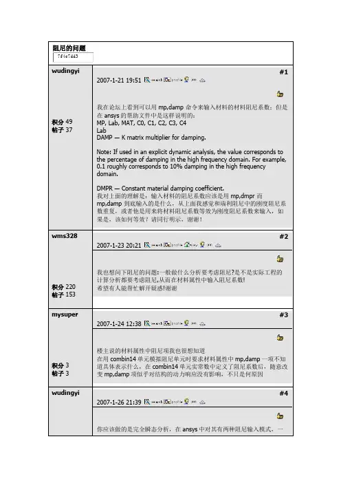
阻尼的问题wudingyi积分 49 帖子 37#12007-1-21 19:51我在论坛上看到可以用mp,damp 命令来输入材料的材料阻尼系数;但是在ansys 的帮助文件中是这样说明的: MP, Lab, MAT, C0, C1, C2, C3, C4 LabDAMP ― K matrix multiplier for damping.Note: If used in an explicit dynamic analysis, the value corresponds to the percentage of damping in the high frequency domain. For example, 0.1 roughly corresponds to 10% damping in the high frequency domain.DMPR ― Constant material damping coefficient .我对上面的理解是:输入材料的阻尼系数应该是用mp,dmpr 而mp,damp 到底输入的是什么,从上面我感觉和瑞利阻尼中的刚度阻尼系数重复,或者他是用来将材料阻尼系数等效为刚度阻尼系数来输入,如果是,该如何等效?请同行明示,谢谢!wms328积分 220 帖子 153#22007-1-23 20:21我也想问下阻尼的问题:一般做什么分析要考虑阻尼?是不是实际工程的计算分析都要考虑阻尼,从而在材料属性中输入阻尼系数! 希望有人能帮忙解开疑惑!谢谢mysuper积分 3 帖子 3#32007-1-24 12:38楼主说的材料属性中阻尼项我也很想知道在用combin14单元模拟阻尼单元时要求材料属性中mp,damp 一项不知道具体表示什么,在combin14单元实常数中定义了阻尼系数后,随意改变mp,damp 项似乎对结构的动力响应没有影响,不只是何原因wudingyi#42007-1-26 21:39你应该做的是完全瞬态分析,在ansys 中对其有两种阻尼输入模式,一积分 49 帖子 37 个是mp,damp 输入材料阻尼,另一个是单元阻尼,而对于其他一切的以阻尼比的形式输入的阻尼参数,程序一律忽略。
ansys 提取质量刚度阻尼矩阵
在ANSYS中,可以使用以下步骤来提取质量、刚度、阻尼矩阵:
打开ANSYS软件,并导入需要分析的模型。
在主界面中,选择“工具”菜单中的“质量特性”,打开“质量特性”对话框。
在“质量特性”对话框中,选择“全局质量矩阵”,然后单击“计算”按钮。
在计算完成后,将显示全局质量矩阵、全局刚度矩阵和全局阻尼矩阵。
可以使用类似的方法提取其他相关矩阵,例如局部质量矩阵、局部刚度矩阵和局部阻尼矩阵。
需要注意的是,在提取矩阵之前,需要对模型进行正确的材料属性设置和边界条件设置。
此外,对于复杂模型,可能需要使用其他工具或方法来提取矩阵。
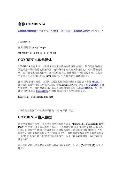
Ansys中文帮助-单元详解-COMBIN14 COMBIN14Element Reference(单元参考)> Part I (第一部分). Element Library(单元库)>COMBIN14弹簧-阻尼器Spring-DamperMP ME ST <> <> PR <> <> <> PP EDCOMBIN14单元描述COMBIN14 具有1 维,2 维或3 维应用中的轴向或扭转的性能。
轴向的弹簧-阻尼器选项是一维的拉伸或压缩单元。
它的每个节点具有3个自由度:x,y,z 的轴向移动。
它不能考虑弯曲或扭转。
扭转的弹簧-阻尼器选项是一个纯扭转单元。
它的每个节点具有3个自由度的:x,y,z的旋转。
它不能考虑弯曲或轴向力。
弹簧-阻尼器没有质量。
质量可以通过其他合适的质量单元添加(参阅MASS21)。
弹簧或阻尼特性可以在单元里去除。
参阅ANSYS, Inc.理论指南中的COMBIN14的更多介绍。
更一般的弹簧或阻尼单元可以用刚度矩阵单元(MATRIX27)。
另一种弹簧-阻尼单元是COMBIN40, 它的作用方向由节点坐标方向决定。
COMBIN14几何形状2 维单元必须位于z=常数的平面内(即xy平面-译注)COMBIN14输入数据这个单元的几何形状,节点位置和坐标系统可以在“Figure 14.1 COMBIN14几何形状”中找到。
这个单元由两个节点,一个弹簧常数(k)和阻尼系数(c v)1 和(c v)2组成。
阻尼特性不能用于静力或无阻尼的模态分析。
轴向弹簧常数的单位是“力/长度”,阻尼系数的单位是“力*时间/长度”。
扭转弹簧常数和阻尼系数的单位是“力*长度/弧度”和“力*长度*时间/弧度”。
对于2维轴对称问题,这些值应该基于360°。
单元的阻尼部分只是把阻尼系数传到结构阻尼矩阵。
阻尼力(F) 或扭矩(T) 由下式计算:F x = - c v du x/dt or Tθ = - c v d θ/dt这里c v是阻尼系数,由c v = (c v)1 + (c v)2v式确定。
ansys接触稳定阻尼因数Ansys接触稳定阻尼因数是指在分析和模拟中,使用Ansys软件时,为了保证计算结果的稳定性和精确性,引入的一种参数。
它在动态分析中起到了重要的作用,可以有效地控制模型的振动幅度和振动周期。
本文将对Ansys接触稳定阻尼因数进行详细介绍,并探讨其在工程实践中的应用。
我们需要了解什么是接触稳定阻尼。
在工程领域中,接触是一种常见的现象,比如机械零件之间的接触、结构与地基的接触等。
当两个物体之间存在接触时,由于摩擦力和接触面的变形等因素的影响,会导致振动的发生。
而接触稳定阻尼因数就是用来控制这种振动的参数。
Ansys软件是一款常用的工程仿真软件,可以对各种工程问题进行模拟和分析。
在进行动态分析时,如果不引入接触稳定阻尼因数,模型可能会出现不稳定的情况,振动幅度会越来越大,甚至无法得到合理的结果。
而引入接触稳定阻尼因数后,可以有效地控制振动幅度,使模型的振动趋于稳定。
那么,如何确定接触稳定阻尼因数呢?一般来说,这需要根据具体的工程问题和模型特点来确定。
在Ansys软件中,可以通过设置接触稳定阻尼因数的数值来控制模型的振动。
一般情况下,接触稳定阻尼因数的数值越大,模型的振动越稳定。
但是过大的数值也会导致计算时间增加,影响计算效率。
在实际工程中,接触稳定阻尼因数的选择需要考虑多个因素。
首先,需要分析模型的振动特性和振动频率。
不同的振动频率对应不同的接触稳定阻尼因数,需要根据实际情况进行调整。
其次,还需要考虑模型的材料特性和接触面的摩擦系数等因素。
这些因素都会对接触稳定阻尼因数的选择产生影响。
接触稳定阻尼因数的选择也需要结合实际的工程要求。
在某些情况下,为了保证模型的振动稳定性,可能需要增大接触稳定阻尼因数的数值。
而在另一些情况下,为了减小计算时间和提高计算效率,可能需要适当降低接触稳定阻尼因数的数值。
这需要工程师根据实际情况进行综合考虑,并进行优化设计。
Ansys接触稳定阻尼因数在工程实践中起到了重要的作用。
ANSYS 查询函数(Inquiry Function)在ANSYS操作过程或条件语句中,常常需要知道有关模型的许多参数值,如选择集中的单元数、节点数,最大节点号等。
此时,一般可通过*GET命令来获得这些参数。
现在,对于此类问题,我们有了一个更为方便的选择,那就是查询函数— Inquiry Function。
Inquiry Function类似于ANSYS的 *GET 命令,它访问ANSYS数据库并返回要查询的数值,方便后续使用。
ANSYS每执行一次查询函数,便查询一次数据库,并用查询值替代该查询函数。
假如你想获得当前所选择的单元数,并把它作为*DO循环的上界。
传统的方法是使用*GET命令来获得所选择的单元数并把它赋给一个变量,则此变量可以作为*DO循环的上界来确定循环的次数*get, ELMAX,elem,,count*do, I, 1, ELMAX……*enddo现在你可以使用查询函数来完成这件事,把查询函数直接放在*DO循环内,它就可以提供所选择的单元数*do, I, ELMIQR(0,13)……*enddo这里的ELMIQR并不是一个数组,而是一个查询函数,它返回的是现在所选择的单元数。
括弧内的数是用来确定查询函数的返回值的。
第一个数是用来标识你所想查询的特定实体(如单元、节点、线、面号等等),括弧内的第二个数是用来确定查询函数返回值的类型的(如选择状态、实体数量等)。
同本例一样,通常查询函数有两个变量,但也有一些查询函数只有一个变量,而有的却有三个变量。
查询函数的种类和数量很多,下面是一些常用、方便而快速快捷的查询函数1 AREA—arinqr(areaid,key)areaid—查询的面,对于key=12,13,14可取为0;key—标识关于areaidr的返回信息=1,选择状态=12,定义的数目=13,选择的数目=14,定义的最大数=-1,材料号=-2,单元类型=-3,实常数=-4,节点数=-6,单元数…arinqr(areaid,key)的返回值对于key=1=0, areaid未定义=-1,areaid未被选择=1, areaid被选择…2 KEYPOINTS—kpinqr(kpid,key)kpid—查询的关键点,对于key=12,13,14为0 key —标识关于kpid的返回信息=1,选择状态=12,定义的数目=13,选择的数目=14,定义的最大数目=-1,数料号=-2,单元类型=-3,实常数=-4,节点数,如果已分网=-7,单元数,如果已分网kpinqr(kpid,key)的返回值对于key=1=-1,未选择=0,未定义=1,选择3 LINE—lsinqr(lsid,key)lsid—查询的线段,对于key=12,13,14为0 key—标识关于lsid的返回信息=1,选择状态=2, 长度=12,定义的数目=13,选择的数目=14,定义的最大数=-1,材料号=-2,单元类型=-3,实常数=-4,节点数=-6,单元数…4 NODE—ndinqr(node,key)node—节点号,对于key=12,13,14为0 key—标识关于node的返回信息=1,选择状态=12,定义的数目=13,选择的数目=14,定义的最大数=-2,超单元标记=-3,主自由度=-4,激活的自由度=-5,附着的实体模型ndinqr(node,key)的返回值对于key=1=-1,未选择=0,未定义=1,选择5 VOLUMES—vlinqr(vnmi,key)vnmi—查询的体,对于key=12,13,14为0key—标识关于vnmi的返回信息=1,选择状态=12,定义的数目=13,选择的数目=14,定义的最大数目=-1,数料号=-2,单元类型=-3,实常数=-4,节点数=-6,单元数=-8,单元形状=-9,中节点单元=-10,单元坐标系vlinqr(vnmi,key)的返回值对于key=1=-1,未选择=0,未定义=1,选择ANSYS能实现直接流-固耦合分析吗?ANSYS流固耦合分析有三种形式,可以实现全直接或半直接耦合分析:一: ANSYS/Mechanical模块或含该模块的软件包中的流固耦合分析功能,但此处的流体是非流动的流体,而是静流体,它计算流体由于重力、惯性力、波动压力等引起的分布压力载荷与结构的相互作用。
ANSYS学说模态提取方法在ANSYS 中有以下几种提取模态的方法:– (1) Block Lanczos 法– (2) 子空间法– (3) PowerDynamics 法– (4) 减缩法– (5) 不对称法– (6) 阻尼法使用何种模态提取方法主要取决于模型大小(相对于计算机的计算能力而言)和具体的应用场合。
(1) Block Lanczos 法Block Lanczos 法可以在大多数场合中使用:- 是一种功能强大的方法,当提取中型到大型模型(50,000 ~ 100,000 个自由度)的大量振型时(40+),这种方法很有效;- 经常应用在具有实体单元或壳单元的模型中;- 在具有或没有初始截断点时同样有效。
(允许提取高于某个给定频率的振型);- 可以很好地处理刚体振型;- 需要较高的内存。
(2) 子空间法子空间法比较适合于提取类似中型到大型模型的较少的振型(<40)- 需要相对较少的内存;- 实体单元和壳单元应当具有较好的单元形状,要对任何关于单元形状的警告信息予以注意;- 在具有刚体振型时可能会出现收敛问题;- 建议在具有约束方程时不要用此方法。
(3) PowerDynamics 法PowerDynamics 法适用于提取很大的模型(100.000个自由度以上)的较少振型(< 20)。
这种方法明显比Block Lanczos 法或子空间法快,但是:- 需要很大的内存;- 当单元形状不好或出现病态矩阵时,用这种方法可能不收敛;- 建议只将这种方法作为对大模型的一种备用方法。
注: PowerDynamics 方法- 子空间技术使用Power 求解器(PCG) 和一致质量矩阵;- 不执行Sturm 序列检查(对于遗漏模态); 它可能影响多个重复频率的模型;- 一个包含刚体模态的模型, 如果你使用PowerDynamics 方法,必须执行RIGID 命令(或者在分析设置对话框中指定RIGID 设置)。