XCIT20160302ccs测试
- 格式:xls
- 大小:23.50 KB
- 文档页数:2

ccs tool 使用方法
如何使用CCS(Control Chart Studio)工具:
1. 下载和安装CCS工具。
你可以从官方网站或其他可靠的资源中获得CCS的安装程序。
2. 打开CCS工具,创建一个新的项目。
3. 在项目中,选择需要创建控制图的数据集。
你可以从CCS 中导入数据集,或者手动输入数据。
4. 根据你的需要选择要创建的控制图类型,如 X-Bar控制图、R控制图、S控制图等。
5. 在数据集中选择要分析的变量,并选择相应的控制限。
CCS 将根据数据和选择的控制限自动计算并绘制控制图。
6. 查看绘制的控制图,并根据图表上显示的控制限分析数据的稳定性和过程能力。
7. 对于任何异常或违反控制限的数据点,你可以选择标记、调查和处理它们。
8. CCS还提供功能强大的分析工具,如散点图、箱线图、正态性检验等,可以帮助你进一步分析数据的分布和关系。
9. 导出控制图和分析结果,以便与其他人共享或进行报告。
以上是CCS工具的一般使用方法。
具体的步骤可能会有所不同,具体取决于不同版本和配置的CCS工具。
在使用CCS之前,建议阅读相关的使用手册或参考文档,以获得更详细的指导。

TIDSP软件开发工具CCS的使用首先,我们来讨论创建一个新的CCS工程。
在CCS主界面中,选择File -> New -> CCS Project。
在弹出的对话框中,选择项目的名称和位置,然后选择设备和使用的编译器。
CCS支持多种设备和编译器,包括MSP430、C2000、Stellaris等。
当我们的代码编译成功后,我们可以开始调试应用程序。
CCS提供了多种调试工具,包括仿真器、调试器和性能分析工具。
我们可以选择合适的调试工具,连接到我们的硬件平台上,并开始调试应用程序。
CCS的调试器可以提供单步执行、断点、变量监视等功能,帮助我们快速定位和修复问题。
在调试过程中,有时候我们需要对性能进行优化。
CCS提供了性能分析工具,可以帮助我们找到应用程序中的性能瓶颈。
我们可以使用该工具来分析代码的执行时间和内存占用,找到需要改进的部分并采取相应的优化措施。
除了以上提到的功能,CCS还提供了许多其他的开发和调试工具。
例如,CCS支持集成第三方软件包和库文件,可以扩展应用程序的功能。
CCS还支持版本控制系统,可以帮助我们管理代码的版本和变更。
此外,CCS还提供了用于执行批处理和自动化构建的命令行接口。
总结来说,TIDSP软件开发工具CCS是一个功能丰富的集成开发环境,用于开发和调试基于TI处理器的实时应用程序。
通过CCS,我们可以创建工程、编写代码、调试应用程序并优化性能。
这个软件提供了多种工具和功能,帮助开发者提高开发效率,并加速应用程序的上市时间。
无论是初学者还是有经验的开发者,CCS都是一个强大而易于使用的软件开发工具。

实验一CCS软件入门实验1. 实验目的(1)通过学习CCS软件的说明和介绍了解如何使用CCS软件;(2)熟悉如何建立工程,修改文件,编译运行程序;(3)了解控制DSP的基本工作流程;(4)学会阅读英文文档资料,按照文档介绍解决实际遇到的问题。
2. 实验内容本实验要求通过在课上学习的CCS使用方法,结合书上内容和CCS的帮助文档,按照CCS英文文档的步骤在CCS上建立一个简单的DSP工程文件。
学习如何建立工程、如何添加文件、设置程序选项、编译工程、定位错误、修改错误、运行程序、查看结果、分析程序等。
要求对每一个工程都要认真完成,彻底学会使用CCS软件。
CCS(Code Composer Studio)代码调试器是TI公司专为DSP开发提供的一种集成开发环境(IDE, Integrated Development Environment),在Windows操作系统下,采用图形接口界面,提供环境配置、源文件编辑、程序调试、跟踪和分析等工具,帮助用户完成DSP系统开发。
CCS有两种工作模式,即软件仿真器(Simulator)和硬件仿真器(Emulator)。
软件仿真器工作可以脱离DSP芯片,在PC上模拟DSP的指令和工作机制,主要用于前期DSP开发中算法的实现和调试。
硬件仿真需要运行在DSP芯片上,与硬件开发板联合在线编程和调试。
本节实验将学习和使用软件仿真模式,同学们在自己的电脑上进行编程时采用这种模式。
3 实验步骤一、配置CCS为软件仿真模式1)打开桌面上的Setup CCS 2 ('C5000)图标;进入如下界面:2)点中Clear,将原始配置清除;3)选中如下界面的选项:4)点击Import按钮。
5)点击Save and Quit;出现如下提示:6)选择“是”,启动CCS软件二、按照CCS自带的帮助文件建立工程、调试等2.1 建立新的工程1.选择菜单项Project→New。
2.2 向工程添加文件1.选择Project→Add Files to Project,选择hello.c并点击Open。
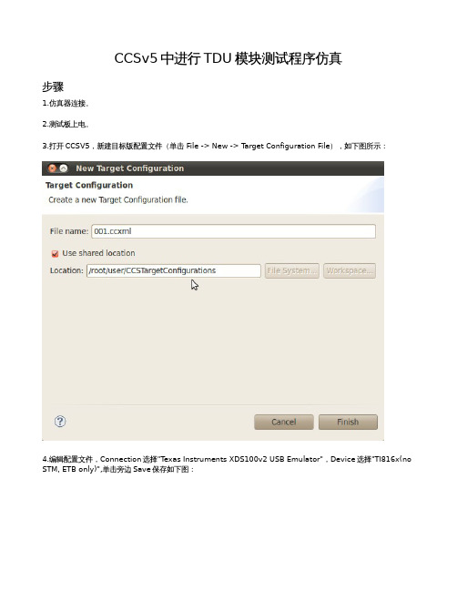
CCSv5中进行TDU模块测试程序仿真步骤1.仿真器连接。
2.测试板上电。
3.打开CCSV5,新建目标版配置文件(单击File -> New -> T arget Configuration File),如下图所示:4.编辑配置文件,Connection选择"T exas Instruments XDS100v2 USB Emulator",Device选择"TI816x(no STM, ETB only)",单击旁边Save保存如下图:5.启动选定配置(单击Window -> Show View -> T arget Configurations, 右击User Defined 下的xml,单击Launch Selected Configuration)6.打开Debug窗口(单击Window -> Show View -> Debug),右击"T exas Instruments XDS100v2 USB Emulator_0/CortexA8 (Disconnected:Unknown)",单击Connect T arget,连接板,连接后如图所示:7.右击"T exas Instruments XDS100v2 USB Emulator_0/CortexA8 (Suspended)",单击"Open GEL Files View",在以下"GEL Files"窗口中空白处,右击,单击"Load GEL",结果如下所示:8.ARM内存初始化(单击Scripts -> DM816x External Memories -> DDR3_796MHZ_doall),完成后如下图所示:9.DSP内存初始化(单击Scripts -> DM816x Omx Init -> C674),出现如下图示即表示连接DSP成功。
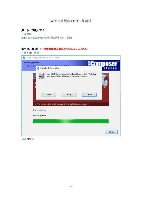
Win10系统装CCS3.3并调试
第一步,下载CCS3.3
下载地址:
/s/1kTxkMRd 密码:2dia;
第二步,装CCS(一定要按照默认路径C:\CCStudio_v3.3PLA)一路next,遇见
点击Ignore
同样点击Ignore
此处警告,不理会。
至此软件安装完成。
第三步,装驱动(此处使用的是SEED-XDS510PLUS仿真器)
下载地址:
/index.php/Home/Down/down/action/down/topId/1.html
安装过程中(一路默认,自动选择安装路径为C:\CCStudio_v3.3PLA)
安装完成后,将SEED-XDS510PLUS仿真器接在计算机USB口,打开设备管理器。
可以看到,SEED-XDS510仿真器驱动安装完成!
此处选择TMS320C6713板,保存和退出,同时进入CCS3.3开发环境。
可以看到在WIN10系统下的SEED-XDS510完美支持CCS3.3开发环境。
第四步,试验
打开LED project,并连接(Debug->connect,或ALT+C)
运行中:
停止:
至此,在win10系统下安装CCS3.3并完成调试顺利完成,在此证明WIN10系统下完美支持CCS3.3。

实验1:CCS基本操作实验一、实验项目与目的重点学习CCS中断点、探针、代码剖析器、图形工具、数据追踪与Matlab操作等的使用技巧,练习C语言和汇编语言编程及调试。
二、实验设备计算机,CC4.1版软件三、实验内容与步骤1.CCS设置双击桌面上的图标,先选择Close,进入如图4.1所示的配置对话框。
由于本实验采用软件仿真器(Simulator)进行软件仿真,因此应从Available Board/Simulator Types列表栏中选择C2xx Simulator,在C2xx Simulator上单击右键,选择Add to System。
然后单击Finish 即可。
注意:如果要从另一种平台(例如Sdgo2xx)中转变为C2xx Simulator平台,应右击System Configuration列表中的该平台,再选择Remove删除,然后才能按照本步骤对CCS 进行设置。
图4.1 CCS设置2.创建新项目文件(1)在“C:\tic2xx\myprojects”目录下创建一个名为volume的目录,将本书配套的实验1“exp01_volume”目录下的所有文件复制到该目录下。
(2)双击桌面上的图标,启动CCS。
(3)在Project菜单下点击New,在出现的项目创建窗口中输入项目文件名称。
名称任意,例如“volume”,文件后缀*.mak可省略。
3.向项目中加入文件(1)在项目文件查看窗口中的volume.mak上单击右键(如图4.2所示),选择Add Files,或者选择Project→Add Files to Project,此时出现如图4.3所示的添加文件窗口,在“文件类型”中选择要加入的文件的文件类型。
将应用程序volume.c(主程序可以是C程序 *.c,也可以是汇编程序 *.asm)、命令链接文件 *.cmd(volume.cmd)等分别加入。
如果需要用到中断向量,加入中断向量文件vectors.asm;如果用到了C程序,还需加入实时运行支持库文件rts2xx.lib。
Adding a Probe Point for File I/O设置探针This lesson shows you how to use a Probe Point to transfer the contents of a PC file to the target for use as test data. It also uses a breakpoint to update all the open windows when the Probe Point is reached. As with breakpoints, there are both software and hardware probe points, this tutorial will only use software probe points.1.Choose File Load Program. Select volume1.out, and click Open.2.Double-click on the volume.c file in the Project View.3.Put your cursor in line 61 (your line number may vary) of the main functionthat says:4.dataIO();The dataIO function acts as a placeholder, you will add to it later. For now, it is a convenient place to connect a Probe Point that injects data from a PC file.4.Click the (Toggle Probe Point) toolbar button. The selection marginindicates that a probepoint has been set (blue icon).5.From the File menu, choose File I/O. The File I/O dialog appears, and youmay now select input and output files.6.In the File Input tab, click Add File.7.Browse to the volume1 project folder you created, select sine.dat and clickOpen.Note: Notice that you can select the format of the data in the Files of Type box. The sine.dat file contains hex values for a sine waveform.A control window for the sine.dat file appears. (It may be covered by the main window.) Later, when you run the program, you can use this window to start, stop, rewind, or fast forward within the data file.8.In the File I/O dialog, change the Address to inp_buffer and the Length to100. Also, put a check mark in the Wrap Around box.∙The Address field specifies where the data from the file is to be placed.The inp_buffer is declared in volume.c as an integer array of BUFSIZE (aconstant that is defined in volume.h).∙The Length field specifies how many samples from the data file are read each time the Probe Point is reached. You use 100 because that is the value set for the BUFSIZE constant in volume.h (0x64).∙The Wrap Around option causes the IDE to start reading from the beginning of the file when it reaches the end of the file. This allows the data file to be treated as a continuous stream of data even though it contains only 1000 values and 100 values are read each time the Probe Point is reached.9.Click Add Probe Point. The Probe Points tab of the Break/Probe Points dialogappears.10.In the Probe Point list, highlight the line that says VOLUME.C line 61 -->No Connection. Your line number may vary.11.In the Connect To field, click the down arrow and select the FILEIN:C:\...\sine.dat file from the list.12.Click Replace. The Probe Point list changes to show the Probe Point connectedto the sine.dat file.13.Click OK. The File I/O dialog shows that the file is now connected to a ProbePoint.14.Click OK to close the File I/O dialog.Displaying Graphs显示图如果您运行的程序现在只显示下图,你不会看到程序做了什么There are a variety of ways to graph data processed by your program. In this example, you view a signal plotted against time. You open the graphs in this section and run the program in the next section.1、Choose View→Graph→Time/Frequency.2、In the Graph Property Dialog, change the Graph Title, Start Address, AcquisitionBuffer Size, Display Data Size, DSP Data Type, Autoscale, and Maximum Y-value properties to the values shown here. Scroll down or resize the dialog box to see all the properties.3.Click OK. An Input graph window for the Input Buffer appears.4.Right-click on the Input graph window and choose Clear Display from the pop-upmenu.5.Choose View→Graph→Time/Frequency again.6.This time, change the Graph Title to Output and the Start Address toout_buffer. All the other settings are correct7.Click OK to display the Output graph window. Right-click on the Output graphwindow and choose Clear Display from the pop-up menu.So far, you have placed a Probe Point, which temporarily halts the target, transfers data from the host PC to the target, and resumes execution of the target application. However, the Probe Point does not cause the graphs to be updated. In this section, you create a breakpoint that causes the graphs to be updated and use the Animate command to resume execution automatically after the breakpoint is reached1.In the volume.c window, put your cursor in the line that calls dataIO.2.Click the (Toggle Breakpoint) toolbar button or press F9. A red iconappears in the selection margin next to the blue icon, to designate the breakpoint.You put the breakpoint on the same line as the Probe Point forcing the target to halt only once to perform both operations—transferring the data and updating the graphs.3.Arrange the windows so that you can see both graphs.4.Click the (Animate) toolbar button or press F12 to run the program.5.Each time the Probe Point is reached, the IDE gets 100 values from the sine.datfile and writes them to the inp_buffer address6.Choose Debug→Halt to quit running the program.Adjusting the Gain(增益调整)Recall from Reviewing the Source Code that the processing function multiplies each value in the input buffer by the gain and puts the resulting values into the output buffer. It does this by performing the following statement within a while loop:1.*output++ = *input++ * gain;This statement multiplies a value in inp_buffer by the gain and places it in the corresponding location in the out_buffer. The gain is initially set to MINGAIN, which is defined as 1 in volume.h. To modify the output, you need to change the gain. One method is to use a watch variable.1.Choose View→Watch Window and select the Watch1 tab.2.Click on the expression icon in the Name column and type gain as the nameof the variable to watch.3.Click on the white space in the watch window to save the change. The valueshould immediately appear.4.If you have halted the program, choose Run from the Debug menu to restartthe program. Observe the input and output graph you created earlier.5.From the Debug menu, choose Halt.6.In the Watch Window, select the value of gain (1) and change it to 10.7.From the Debug menu, choose Run. Notice that the amplitude of the signal inthe Output graph changes to reflect the increased gain as in the following example:8.From the Debug menu, choose Halt.9.From the Project menu, choose Close.10.Save the program when prompted, and Close all other windows and graphs.11.Remove all probe points and breakpoints before moving to the next lesson. This concludes Developing a Simple Program.。
海上移动平台检验中国船级社湛江分社2000年9月6日目录第一篇总则第二篇平台结构第三篇轮机装置第四篇电气设备第五篇救生设备第六篇消防设备第七篇无线电通信导航设备第八篇载重线证书第九篇防污设备第十篇起重设备第一篇总则目录第一章移动平台的各种证书第二章移动平台建造后的各种检验第一章移动平台的各种证书根据平台规范、规则、安全规则、国际公约及有关规定,海上移动式平台应持有如下各种证书:(1) 有关入级检验的证书证书名称格式有效期依据1)海上移动式平台入级证书 CCM 五年 82规范/92规范 2)临临时海上移动式平台入级证书 CCM-I 5个月证书名称格式有效期依据1)国际船舶吨位证书(1969) CIT-2 长期 69国际船舶吨位丈量公约2) 海上移动平台载重线证书 CLL-M 五年 69国际船舶载重线公约3)海上移动平台防油污证书 CPP-U 五年 73/78MAPOL4)海上移动平台安全证书 SCM 五年 79、89MODV SOLAS5)船舶起重和起货设备检验簿 RLA-2 长期劳工组织32号公约6)海上移动平台检验合格证书 SCMF 一年(仅适用于外国籍平台)7)平台防止生活污水污染证书 CSW-U 五年8)海上移动平台适拖证书 TCM9)起重设备检验和试验证书 CLA-210)活动零部件检验和试验证书 CLG-211)铁制活动零部件热处理证书 CHT-212)钢索检验和试验证书 CWR-2以上各种证书各自依据一定的公约、规则或规范而签发,其约束的范围,所证明的内容项目各不相同,证书的作用不同。
1、国际船舶吨位证书(1969) CIT-2 长期吨位证书是国家证书,由政府授权签发,••用于证明移动平台的总吨位和净吨位。
目前使用<<国际船舶吨位证书(1969)>>CIT-2,根据1969年国际船舶吨位丈量公约的规定,套用船用吨位丈量方法。
规则中有许多规定,不适用于平台的地方,只能参照处理,酌情确定。
IE浏览器没有发送按钮,信息无法
发送
小气候设备ID无法填写,导致
靶标害虫无法关联小气候
需要在查看收到的信息时,添加一
个导出按钮,能将收到的信息以
word形式导出
登陆个体账户时无法查看生态远程
监控
生态远程监控页面兼容性差 CCS系统测试报告
祥辰科技有限公司信息技术部 2016.03.01
存在漏洞处理方式测报灯设备在右侧地图上不显示
生长期设置中,删除按钮不能用
需要在小气候折线图上添加一个
导出按钮,能够将折线图导出
是是
是否解决是是是否是是苗情预警苗情预警预警信息CCS后台
管理系统设备管理16
17
18所属模块设备监控系统设置灾情预警预警信息10
11
12
13
14
15
编号12345678
18 19。