4-20mA输出电流传感器BA系列说明书
- 格式:pdf
- 大小:139.88 KB
- 文档页数:3
Baelz自动化控制器第一页操作指南微处理器——基于控制器ucelsitron baelz 6490/baelz 6590通用型三位——步控制器带有特殊的PID逐级控制器计算工业控制器操作简单使用者定义操作级过程参数与设定值数字显示PI和PID控制结构两位控制3位控制Pt100,电流和电压信号的测量输入手动/自动转换紧凑设计96㎜×96㎜×135㎜2个可调的设定值遥控设定值设定值斜线上升通过数字输入进行控制串行接口强大的自我优化数据保护的半导体记忆插入式接线端保护级别Front 1P65紧凑设计 48㎜×96㎜×140㎜目录第二页1.功能简介2.操作与设置2.1在自动模式下设定值2.2手动模式下打开/关闭执行元件2.3参数/结构级分支2.4第二操作级分支(使用者定义操作级)2.5设定参数/结构点3.参数化/结构级3.1优化:自动决定有利的控制参数3.2比例带Pb3.2.3位控制器3.3积分作用时间tn3.3.1双位控制器3.4微分作用时间3.5死区3.6动作时间/阀门起动时间3.7报警(649010/01/2和659010/1/2)3.8报警继电器(在6490/3/4/5和6590/3/4/5)3.9 LED显示小数点3.10过程变量显示PV缩放3.11设定值限值3.12遥控/本地转换(6490/1/2/5和6590/1/2/5)3.13第二定值SP2(6490/2/3/4和6590/2/3/4)3.14定值斜线变化Spr3.15定值斜线变化趋势3.16过程增益P.G3.17过程变量PV的输入(输入PV)3.18遥控定值的输入(输入SP)(6490/1/2/5和6590/1/2/5)3.19进程变量PV的测量值过滤器3.20对传感器故障PV的应答(传感器断开)3.21自动/手动转换互锁3.22控制器动作趋势3.23数字化输入(开始、关闭、停止)的功能(6490/3/4和6590/3/4)3.24串行接口传输速度(6490/3/4和6590/3/4)3.25串行接口地址/名称(6490/3/4和6590/3/4)3.26串行通信(6490/3/4和6590/3/4)3.27第二操作级(操作级2)3.28参数/结构级访问(密码)4.安装5.电力连接5.1线路图6.试运转/试车7.技术参数8.订货号码baelz 6490/baelz /65909.参数/结构级,数据列表总览警告:在电力设备操作中,部分元件与高压相联的危险性是不可避免的。


LAURELELECTRONICS, INC.4-20 mA & Serial Data Output Transmitter for Thermocouple Types J, K, T, E, N, R, SFeatures• 4-20 mA, 0-20 mA, 0-10V or -10V to +10V transmitter output, 16 bits, isolated • RS232 or RS485 serial data output, Modbus or Laurel ASCII protocol, isolated • Dual 120 mA solid state relays for alarm or control, isolated• Factory calibrated for thermocouple types J, K, T, E, N, R, S in one range • User selectable input span from entire thermocouple range down to 15.0° • Output update rate to 60/sec• Analog output resolution 0.0015% of span (16 bits), accuracy ±0.02% of span • 5V, 10V or 24V dc transducer excitation output, isolated• Universal 85-264 Vac / 90-300 Vdc or 10-48 Vdc / 12-32 Vac power•DIN rail mount housing only 22.5 mm wide, detachable screw-clamp connectorsDescriptionThe Laureate thermocouple transmitter provides a linearized, highly accurate, stable and repeatable transmitter output forthermocouple types J, K, T, E, N, R or S. The thermocouple type and temperature range, specified in °C or °F, are user-selectable. The temperature range can be as wide as the entire span of the thermocouple type, or as narrow as 150 counts (such as 15.0°), limited only by considerations of electrical noise and digital filtering time constants.All ranges for all thermocouple types are digitally calibrated at the factory, with calibration factors stored in EEPROM on the signal conditioner board. This allows temperatures sensors and signal conditioner boards to be changed in the field without re-calibrating the meter. A cold junction compensation (CJC) unit is calibrated as a system with the signal conditioner board. That unit encloses the thermocouple junctions and the junction tem-perature sensor in the same isothermal space so as to minimizecold junction compensation errors.Fast read rate at up to 50 or 60 conversions per second while integrating the signal over a full power line cycle is provided by Concurrent Slope (Pat 5,262,780) analog-to-digital conversion. High read rate is ideal for peak or valley capture and for real-time computer interface and control.Standard features of Laureate transmitters include:• 4-20 mA, 0-10V or -10V to +10V analog transmitter output,isolated, jumper-selectable and user scalable. All selections provide 16-bit (0.0015%) resolution of output span and 0.02% output accuracy of a reading from -99,999 to +99,999 counts that is also transmitted digitally. Output isolation from signal and power grounds eliminates potential ground loops. • Serial communications output, isolated. User selectableRS232 or RS485, half or full duplex. Three protocols are user selectable: Modbus RTU, Modbus ASCII, or Laurel ASCII. Modbus operation is fully compliant with Modbus Over Serial Line Specification V1.0 (2002). The Laurel ASCII protocol allows up to 31 Laureate devices to be addressed on the same RS485 data line. It is simpler than the Modbus protocol and is recommended when all devices are Laureates. • Dual solid state relays, isolated. Available for local alarm or control. Rated 120 mA at 130 Vac or 170 Vdc. • Universal 85-264 Vac power. Low-voltage 10-48 Vdc or12-32 Vac power is optional.Easy Transmitter programming is via Laurel's Instrument Setup Software, which runs on a PC under MS Windows. This software can be downloaded from our website at no charge. The required transmitter-to-PC interface cable is available from Laurel (P/N CBL04).SpecificationsTC Types Range Conformity Error J -210°C to +760°C (-347°F to +1400°F) ±0.09°C (±0.16°F)K -244°C to +1372°C (-408°F to +2501°F) ±0.1°C (±0.17°F)T0°C to +400°C (32°F to 752°F)-257°C to 0°C (-430°F to +32°F)±0.03°C (±0.05°F)±0.2°C (±0.36°F)E -240°C to +1000°C (-400°F to +1830°F) ±0.18°C (±0.32°F)N -245°C to +1300°C (-410°F to +2370°F) ±0.10°C (±0.17°F) R -45°C to +1768°C (-49°F to +3214°F) ±0.17°C (±0.31°F) S -46°C to +1768°C (-51°F to +3213°F) ±0.12°C (±0.22°F) Analog InputCalibrationInput Resistance & Current Max Lead Resistance Overall Error at 25°C Span TempcoRef Junction Tempco Over-Voltage Protection NMR at 50/60 HzCMR, DC-60 HzCMV, DC-60 HzOpen sensor indication NIST Monograph 125 (IPTS-68)1 GΩ, 100 pA1 kΩ max for rated accuracy±0.01 of full scale ±2 counts±0.003% of reading/°C±0.02 deg/deg125 Vac80 dB plus selectable filter from 80 ms to 9.6 s time constant 120 dB with 500Ω imbalance250 Vac from power and earth grounds0 mA or > 20 mA output, selectableAnalog Output (standard)Output Levels Compliance at 20 mA Compliance at 10V Output Resolution Output ErrorOutput Isolation Step response time 4-20 mA, 0-20 mA, 0-10 Vdc, -10 to +10Vdc (user selectable) 10V ( 0-500Ω load )2 mA ( 5 kΩ load or higher)16 bits (65,536 steps)±0.02% of output span ± overall input error250V rms working, 2.3 kV rms per 1 minute test50 msDual Relay Output (standard)Relay Type Load Rating Two solid state relays, SPST, normally open, Form A 120 mA at 140 Vac or 180 VdcSerial Communications (standard)Signal TypesData RatesOutput Isolation Serial Protocols Modbus Modes Modbus Compliance Digital Addressing RS232 or RS485 (half or full duplex)300, 600, 1200, 2400, 4800, 9600, 19200 baud250V rms working, 2.3 kV rms per 1 min test Modbus RTU, Modbus ASCII, Laurel ASCIIRTU or ASCIIModbus over Serial Line Specification V1.0 (2002) 247 Modbus addresses.Up to 32 devices on an RS485 line without a repeaterPower InputStandard Power Low Power Option Power Frequency Power Isolation Power Consumption 85-264 Vac or 90-300 Vdc10-48 Vdc or 12-32 VacDC or 47-63 Hz250V rms working, 2.3 kV rms per 1 min test 2W typicalMechanicalDimensions MountingElectrical Connections 129 x 104 x 22.5 mm case35 mm rail per DIN EN 50022 Plug-in screw-clamp connectorsEnvironmentalOperating Temperature Storage Temperature Relative Humidity Cooling Required 0°C to 55°C-40°C to 85°C95% at 40°C, non-condensingMount transmitters with ventilation holes at top and bottom. Leave 6 mm (1/4") between transmitters, or force air with a fan.PinoutMechanicalOperation as a Fast ON/OFF Controller or Supervisory MonitorWith the optional dual solid state relay output option, which has a typical response time of only 17 ms, Laureate temperature meters and transmitters can serve as extremely fast and accurate ON/OFF con-trollers for closed-loop temperature control. They can also serve as supervisory process monitors and provide alarms or shutoffs when processes exceed normal limits. Multiple setpoint operating modes are individually selectable for each relay. Relay duty cycles and chatter can be minimized with programmable hysteresis and time delays. A band deviation operating mode can be selected for each relay, where an alarm is generated whenever the reading is a selected number of counts above or below the setpoint. The relay modes are non-latching.Ordering GuideCreate a model a model number in this format: LT20JCTransmitter Type LT Laureate 4-20 mA & RS485 TransmitterMain Board2 Standard Main BoardPower0 Isolated 85-264 Vac or 90-300 Vdc1 Isolated 10-48 Vdc or 12-32 VacThermocouple Input JC Thermocouple Type J, -210°C to 760°CJF Thermocouple Type J, -347°F to 1400°FKC Thermocouple Type K, -347°C to 1372°CKF Thermocouple Type K, -408°F to 2501°FTC Thermocouple Type T, -257°C to 400°CTF Thermocouple Type T, -430°F to 752°FEC Thermocouple Type E, -240°C to 1000°CEF Thermocouple Type E, -400°F to 1830°FNC Thermocouple Type N, -240°C to 1000°CNF Thermocouple Type N, -410°F to 2370°FSC Thermocouple Type S, -46°C to 1768°CSF Thermocouple Type S, -51°F to 3214°FR C Thermocouple Type R, -45°C to 1768°CRF Thermocouple Type R, -49°F to 3213°FNote: The same signal conditioner board can be user configured for all thermocouple types listed and °C or °F.Accessories CBL04RS232 cable, 7ft. Connects RS232 screw terminals of LT transmitter to DB9port of PC.CBL02U SB to RS232 adapter cable. Combination of CBL02 and CBL04 connectstransmitter RS232 terminals to PC USB port.。
流量计说明书流量计说明书篇一:流量计使用方法及问题解析流量计外观及使用方法如下所示:接线时1,2,3是电源端使用的是24V供电4是数字量输出,也就是说该引脚输出一定频率的信号,信号的频率与流量相关。
频率关系为1HZ的频率对应一单位NV的的流量(该单位不是清楚是什么)5是模拟量输出,输出的是4-20mA的电流信号,电流大小与流量线性相关。
6、7是RS232串口输出,RXD接收端,TXD发送端。
该端口可以提供与PC的通信功能,也就对应需购买的软件。
连接方式为RX对应9针串口(电脑端口)的2,TX对应9针串口的3,GND 对应9针串口的5。
问题分析及解决方法1、流量计自带LCD屏显示功能,如果不能正常显示说明,电源未正确连接,检查123接线是否正确。
2、如未配液晶屏,需购买。
或通过3条中模拟量或数字量的自制显示单元实现(成本不会很高)3、如果正常显示,流量数显示不正确,说明参数未配置正确 1是输出流量没规律,说明流量计是坏的,需更换2输出线性相关只是大小不正确可通过以下方式解决1)通过串口发送命令对传感器重新标定或设定,但是通信协议需厂家提供。
厂家提供的软件不一定有该功能。
2)通过模拟量输出口,测量输出电流,然后将电流与流量相对应,对应关系可自己设定。
自己做一个小控制器通过这个关系将流量重新显示。
3)通过数字量口,测量频率信号,然后对应流量信号,也需要自己做控制器显示。
4、另一种可能是测量程不匹配,可参照下表确认,内径与最大最小流量的关系流量计说明书篇二:超声波流量计说明书SCT超声波流量计说明书(固定式、便携式通用)MKflo-2000F系列中文版超声波流量计说明书目录一概述 (4)1.1 引言 (4)1.2 SCT的特点 (4)1.3 工作原理 (4)1.6 可选备件 (5)1.7产品型号编码规则 (5)1.8接线图 (6)1.9 性能指标 (6)二开始安装测量 (8)2.1 开箱检查 (8)2.2 供电电源 (8)2.2.1 便携式 (8)2.2.2 固定式 (8)2.2.3 接线 (8)2.3 通电 (8)2.4 键盘 (8)2.5 怎样操作 (9)2.6 窗口简介 (10)2.7 快速输入管道参数和步骤 (10)2.8选择测量点 (11)2.9 探头接线 (11)2.10 安装探头 (12)2.10.1 探头安装距离 (12)2.10.2 探头安装方式 (12)2.10.3 V法 (12)2.10.4 Z法 (12)2.10.5 N法(不常用的方法) (13)2.10.6 W法(极不常用的方法) (13)2.10.7 插入式传感器的安装 (13)2.11 检查安装 (17)2.11.1 信号强度 (17)2.11.2数据数量 (18)2.11.3 总传输时间、时差 (18)2.11.4 传输时间比 (18)2.11.4 安装时注意的问题 (18)三怎样使用 (19)3.1 怎样判断流量计是否工作正常 (19)3.2 怎样选择流量单位制 (19)3.3 怎样选择瞬时流量单位 (19)3.4 怎样选择累积流量单位 (19)3.5 怎样选择累积器倍乘因子 (19)3.6 怎样打开或关闭流量累积器 (19)2MKflo-2000F系列中文版超声波流量计说明书3.7 怎样实现流量累积器清零 (19)3.8 怎样恢复出厂设置 (19)3.9 怎样使用阻尼器稳定流量显示 (20)3.10 怎样使用零点切除避免无效累积 (20)3.11 设置零点提高测量精度 (20)3.12 修改仪表系数(标尺因子)进行标定校正 (20)3.13 密码保护(加锁与开锁) (20)3.14 怎样使用打印机 (21)3.15 怎样使用4~20mA电流环输出 (21)3.16 怎样输出模拟电压信号 (21)3.17怎样输出累积脉冲 (21)3.18 怎样使用OCT输出 (21)3.19 怎样修改日期时间 (21)3.20 怎样调整LCD显示器 (22)3.21 怎样使用RS232串行口 (22)3.22怎样查看每日、每月、每年流量 (22)3.23 怎样对模拟输出进行校准 (22)3.24 查看电子序列号和其他细节 (22)四命令/显示窗口详解 (23)4.1 显示窗口一览表 (23)4.2 显示窗口顺序介绍 (24)五问题处理 (41)表1. 硬件上电自检信息及原因对策 (41)表2. 工作时错误代码原因及对策 (42)其他常见问题问答 (43)六热量和其他物理量测量 (44)6.1 功能介绍 (44)6.2热量测量硬件接线 (44)6.3怎样进行热量测量 (44)6.4温度、压力等信号的量程范围设置 (44)6.5联网时模拟输入量的读取 (44)七质量保证及服务维修支持 (45)7.1 质量保证 (45)7.2 公司服务 (45)7.3 产品升级 (45)7.4 技术咨询 (45)八附录 (46)8.1常用液体声速和粘度 (46)8.2 常用材料声速 (46)8.3水中声速表(1标准大气压下) (47)3MKflo-2000F系列中文版超声波流量计说明书一概述1.1 引言欢迎您选择使用性能更优异、功能更多、采用专利技术制造的MKFLO-2000F系列中文版超声波流量计。
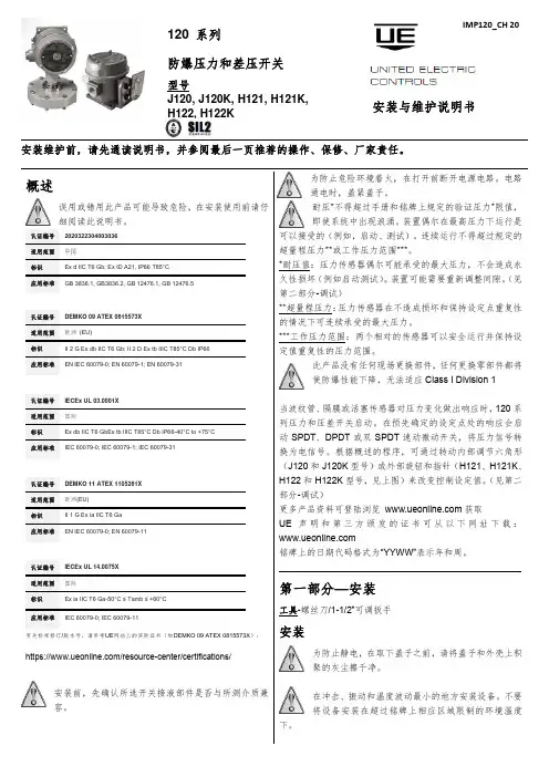
安装维护前,请先通读说明书,并参阅最后一页推荐的操作、保修、厂家责任。
概述误用或错用此产品可能导致危险,在安装使用前请仔细阅读此说明书。
认证编号 2020322304003036适用范围中国标识 Ex d IIC T6 Gb; Ex tD A21, IP66 T85°C应用标准GB 3836.1, GB3836.2, GB 12476.1, GB 12476.5认证编号 DEMKO 09 ATEX 0815573X 适用范围 欧洲 (EU)标识 II 2 G Ex db IIC T6 Gb; II 2 D Ex tb IIIC T85°C Db IP66 应用标准EN IEC 60079-0; EN 60079-1; EN 60079-31认证编号 IECEx UL 03.0001X适用范围 国际标识 Ex db IIC T6 GbEx tb IIIC T85°C Db IP66-40°C to +75°C 应用标准IEC 60079-0; IEC 60079-1; IEC 60079-31认证编号 DEMKO 11 ATEX 1105261X 适用范围 欧洲(EU)标识 II 1 G Ex ia IIC T6 Ga应用标准EN IEC 60079-0; EN 60079-11认证编号 IECEx UL 14.0075X 适用范围 国际标识 Ex ia IIC T6 Ga-50°C ≤ Tamb ≤ +60°C 应用标准IEC 60079-0; IEC 60079-11有关标准修订/版本号,请参考UE 网站上的实际证书(如DEMKO 09 ATEX 0815573X ):https:///resource-center/certifications/安装前,先确认所选开关接液部件是否与所测介质兼容。
为防止危险环境着火,在打开前断开电源电路。
施耐德楼宇自控产品5.1、中央监控软件Vista 5 Standalone提供顺序控制程序、功能联锁程序、用电管理程序、照明控制程序、维修记录程序、统计程序、报表产生程序和历史数据与处理等程序。
系统平台应按实时、多用户和多进程对资源进行分配和管理,系统将拥有事件驱动顺序以及优先结构装置,以便于系统能在同一时间里处理实时情况与紧急任务。
同时,系统平台还具备网络管理、标准网络协议、远程通信管理以及符合计算机技术发展趋势的要求。
软件按模块形式设计,除具备基本功能外,还能提供各种丰富的应用开发功能,例如:OPC、DDE、ODBC等,以利于程序的开发、扩展和修改,支持Lontalk协议,符合有关国际标准和国家标准。
用户界面全部汉化,具备多窗口功能、动态图形显示并且操作直观、简便。
5.2、OPC服务包OPC Client/Sever用于冷热源及变配电系统的集成。
利用定制数据访问,对数据库的数据点进行读/写,从而与OPC Server进行通讯,通过报警接口,接收OPC Server中的报警和事件。
5.3、通讯接口卡PCLTA-21 PCI-card, FTT10LonTalk适配卡、TP/FT-10、通讯速率为78kbps5.4、通讯中继器TAC Xenta Repeater⏹Lonworks网络中继器,用来将网络信号放大,但不会给通讯带来影响。
⏹供电电压24VAC±20%,50-60HZ或19-40VDC,8-28VAC,50/60HZ或8-40VDC⏹功率:最大1.5W⏹环境温度:存储(-20到75摄氏度),运行(0到75摄氏度),湿度(最大90%RH,无冷凝)⏹防护等级IP20⏹中继器数量:任何两个路由器之间最多一个5.5、通讯终端模块LTM网络终端模块,lonworks FTT105.6、直接数字控制器TAC Xenta 401:C⏹微处理器为基础的可编程DDC,CPU采用32位,12.28MHZ 2MB flash memory ,128KB SRAM,最大50条趋势记录,时间表,报警,PID运算控制, DDC通讯符合LonMark标准,并具有lonmark认证标志,具有可脱离中央控制主机独立运行和联网运行能力,最大可支持15个I/O模块。
INTRODUCTION:The 4-20mA Transmitter is designed to operate over 90º, 180º, 360º (option dependent) rotation with ± 5° of over-travel at each end. The Transmitter is direct acting, reverse acting and is also suitable for split ranging (typical setting: 4-12mA or 12-20mA). Position feedback is accomplished through a precision potentiometer that is conductive resin and environmentally sealed. The Triac transmitter features a non-interactive zero and span for easy one step calibration.INSTALLATION:A.Attach proper actuator mounting kit to the transmitter housing using the M6x8 socket head cap screwsprovided.B.Align the switch output shaft to the top of the actuator accessory output shaft and engage the two shaftstogether (or use coupler with non-ISO/NAMUR actuators).C.Attach the bracket assembly to the actuator but do not tighten. Stroke the actuator to allow thetransmitter and actuator to self-align.D.Tighten the transmitter assembly on to the actuator. Note: Steps 3 and 4 can be done prior to calibration. CALIBRATION:A.First select the ‘Action’, direct or reverse. This is accomplished through the location of thepotentiometer ribbon connector plug. Brown wire to ‘D’ for direct or brown wire to ‘R’ for reverse.Factory default setting is ‘D’B.Wire output (+ and -) of transmitter to a regulated current source such as Transmation TM, Altek TM, orFluke TM, meter.C.Operate valve to 50% position (45°). The large spur gear is attached to the drive shaft with a setscrew.Loosen setscrew to disengage the gear. Rotate small spur gear on potentiometer until 12mA is visible on meter. Re-engage large spur gear and tighten the setscrew.D.Rotate actuator closed and turn zero potentiometer (clockwise for higher and counter-clockwise forlower) until meter reads 4mA.E.Rotate actuator open and turn span potentiometer (clockwise for higher and counter-clockwise forlower) until meter is at 20mA.F.For split ranging follow steps 3, 4 and 5 setting zero and span to proper split range: 4 to 12mA or 12 to20 mA.G.Important Note: Disconnect test equipment supply power prior to removing test meter wiring (thetransmitter has CMOS circuitry and is sensitive to voltage/current surges).H.The transmitter is ready for field wiring. Note: If more than one current device is in the loop with thetransmitter, they must be wired in series. Damage may occur if wired incorrectly.SHIELDING:The transmitter is a sensitive precision instrument and if not properly wired is susceptible to intrinsic noise.This could include EMF from inductive loads or RFI from wand held radios.A.The size of wire is dependent on the length of run, it is recommended to use no less than 18 gaugeshielded wire.B.The shield should only be grounded at one end (preferably the source). This acts as an antenna anddirects all noise to ground.TROUBLESHOOTING:1. Problem:Output not continuous throughout actuator/valve stroke (experience a band of max. output).Probable Cause/Solution:Potentiometer out of adjustment (see calibration steps 3 through 9).2. Problem:Transmitter does output 4 or 20mA at desired end of travel.Probable Cause/Solution:Zero or span trim potentiometer is out of adjustment (see calibration steps 4 and 5).3. Problem:Transmitter module has no current signal or provides a constant signal.Probable Cause/Solution:Circuit Board LED not lit:1. Loose or shorted signal connection (no loop power)2. Controller board not responding (replace board).3. Check control sourceCircuit Board LED lit:1. Potentiometer disengaged2. Defective potentiometer or controller board (replace).3. Check control source.SPECIFICATIONS:OHM10KPotentiometer30VDC–12VoltageSupplyLinearity ± 0.5% of full scaleDeadband ± 0.25% of full scaleHysterisis&Action Direct or ReverseZero – Span 20 Turn Trim Potentiometer (Non-interactive)CMOS-ASICLogic/ProcessorA-T Controls products when properly selected, is designed to perform its intended function safely during its useful life. However, the purchaser or user of A-T Controls products should be aware that A-T Controls products might be used in numerous applications under a wide variety of industrial service conditions. Although A-T Controls can provide general guidelines, it cannot provide specific data and warnings for all possible applications. The purchaser / user must therefore assume the ultimate responsibility for the proper sizing and selection, installation, operation, and maintenance of A-T Controls products. The user should read and understand the installation operation maintenance (IOM) instructions included with the product, and train its employees and contractors in the safe use of A-T Controls products in connection with the specific application.While the information and specifications contained in this literature are believed to be accurate, they are supplied for informative purposes only. Nothing contained in this literature should not be considered certified or as a guarantee of satisfactory regarding any matter with respect to this product. Because A-T Controls is continually improving and upgrading its product design, the specifications, dimensions and information contained in this literature are subject to change without notice. Should any question arise concerning these specifications, the purchaser / user should contact A-T Controls.For more information about A-T ControlsFor product specifications go to /A-T Controls, Inc.11363 Deerfield RoadCincinnati, OH 45242Phone: (513) 530-5175Fax: (513) 247-5462。
022BA系列交流电流传感器安装使用说明书V1.4安科瑞电气股份有限公司联系方式:188****5116(微信同号)申明版权所有,未经本公司之书面许可,此手册中任何段落,章节内容均不得被摘抄、拷贝或以任何其它形式复制、传播,否则一切后果由违者自负。
本公司保留一切法律权利。
本公司保留对本手册所描述之产品规格进行修改的权利,恕不另行通知。
订货前,请垂询当地代理商以获悉本产品的最新规格。
目录1产品概述 (1)2型号说明 (1)3通用技术条件 (2)4产品规格 (2)4.1BA05-AI交流电流传感器 (2)4.2BA10-AI交流电流传感器 (3)4.3BA20-AI交流电流传感器 (3)4.4BA50-AI交流电流传感器 (4)5外型及安装 (4)5.1外形及穿孔尺寸 (2)5.1.1BA05-AI交流电流传感器 (4)5.1.2BA10-AI交流电流传感器 (5)5.1.3BA20-AI交流电流传感器 (5)5.1.4BA50-AI交流电流传感器 (5)5.2安装方法 (6)5.3应用实例 (7)6BA50L交流剩余电流传感器 (8)6.1BA50L-AI/I(V)交流剩余电流传感器 (8)6.2BA50L-AI变流剩余电流传感器外型及安装 (8)6.3应用实例 (9)6.3.1单相回路 (9)6.3.2三相三线回路 (10)6.3.3三相四线回路 (11)7接线方式 (12)8订货范例 (13)BA系列产品应用电磁感应原理,对电网中的交流电流进行实时测量,采用恒流和线性补偿技术,将其隔离变换为标准的直流信号输出。
24伏或12伏安全电压供电,可广泛用于工业自动化领域。
BA50L为变流剩余电流互感器主要检测用电系统的漏电流,能随时掌握电气线路和设备的情况,防止因漏电而发生的火灾等事故。
2型号说明BA—/—类型:无——平均值测量T——真有效值测量输出:I——直流电流V——直流电压输入:AI——交流电流穿孔尺寸:(单位:mm)05-φ510-φ1020-φ2050-φ50产品系列代号3通用技术条件电源电压DC12V或24V 功耗≤1W绝缘电阻>100MΩ耐压强度输入/输出、电源之间2.0KV/1min,50Hz 温度系数-10℃~+55℃时,≤400ppm/℃环境温度工作:-10℃~+55℃储存:-25℃~+70℃湿度≤93%RH,不结露,无腐蚀性气体场所海拔≤2000m安装方式TS35导轨,或用螺钉固定柜体上4.1BA05-AI交流电流传感器BA05-AI/I(V)单相交流电流传感器(平均值法测量)BA05-AI/I(V)-T单相交流电流传感器(真有效值法测量)技术参数指标精度等级0.5级输入标称值电流AC0.5A、5A、10A等AC0~(0.5~10A)过载持续1.2倍,瞬时电流10倍/5秒吸收功率≤1VA频响25Hz~800Hz(平均值),25~5kHz(真有效值),特别适合工频场合输出标称值DC4~20mA,或0~20mA,0~5V,0~10V等负载电阻电流输出时≤500Ω,电压输出时≥1KΩ响应时间平均值≤350ms,真有效值≤150ms4.2BA10-AI交流电流传感器BA10-AI/I(V)单相交流电流传感器(平均值法测量)BA10-AI/I(V)-T单相交流电流传感器(真有效值法测量)技术参数指标精度等级0.5级输入标称值电流AC8A、25A、50A等AC0~(8~50)A过载持续1.2倍,瞬时电流10倍/1s秒吸收功率≤1VA频响25Hz~800Hz(平均值),25~5kHz(真有效值),特别适合工频场合输出标称值DC4~20mA,或0~20mA,0~5V,0~10V等负载电阻电流输出时≤500Ω,电压输出时≥1KΩ响应时间平均值≤350ms,真有效值≤150ms4.3BA20-AI交流电流传感器BA20-AI/I(V)交流电流传感器(平均值法测量)BA20-AI/I(V)-T交流电流传感器(真有效值法测量)技术参数指标精度等级0.5级输入标称值电流AC40A、100A、200A等AC0~(40~200)A过载持续1.2倍,瞬时电流10倍/1S吸收功率≤1VA频响25Hz~800Hz(平均值),25~5kHz(真有效值),特别适合工频场合输出标称值DC4~20mA,或0~20mA,0~5V,0~10V等负载电阻电流输出时≤500Ω,电压输出时≥1KΩ响应时间平均值≤350ms,真有效值≤150msBA50-AI/I(V)单相交流电流传感器(平均值法测量)BA50-AI/I(V)-T 单相交流电流传感器(真有效值法测量)技术参数指标精度等级0.5级输入标称值电流AC 60A、300A 、600A等AC 0~(60~600)A过载持续1.2倍,瞬时电流10倍/1S吸收功率≤1VA频响25Hz~800Hz(平均值),25~5kHz(真有效值),特别适合工频场合输出标称值DC4~20mA,或0~20mA,0~5V,0~10V 等负载电阻电流输出时≤500Ω,电压输出时≥1KΩ响应时间平均值≤350ms,真有效值≤150ms5外形及安装5.1外形及穿孔尺寸5.1.1BA05-AI 交流电流传感器5.1.2BA10-AI 交流电流传感器5.1.4BA50-AI交流电流传感器5.2安装方法安装方式可选择导轨安装或螺钉固定安装,具体操作如下:a、导轨安装选择适合的地方安装标准DIN35mm导轨,将BA传感器安装到导轨上即可;b、螺丝固定安装在柜体底板上,选择适合的地方开两个与所安装传感器固定孔位置相对应的螺纹孔;将传感器放置后安装定位螺钉(顺时针)。
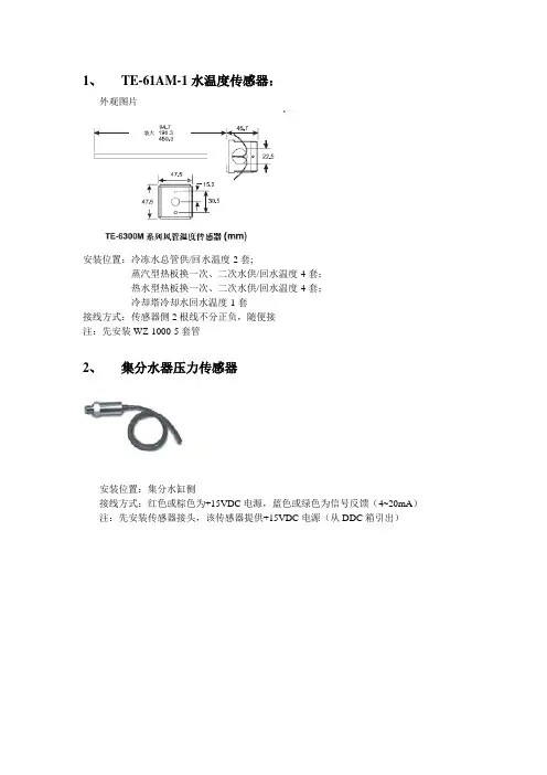
1、TE-61AM-1水温度传感器:外观图片安装位置:冷冻水总管供/回水温度-2套;蒸汽型热板换一次、二次水供/回水温度-4套;热水型热板换一次、二次水供/回水温度-4套;冷却塔冷却水回水温度-1套接线方式:传感器侧2根线不分正负,随便接注:先安装WZ-1000-5套管2、集分水器压力传感器安装位置:集分水缸侧接线方式:红色或棕色为+15VDC电源,蓝色或绿色为信号反馈(4~20mA)注:先安装传感器接头,该传感器提供+15VDC电源(从DDC箱引出)3、P499VBS-404C液体压力变送器安装位置:冷水机组冷冻水总管供/回水压力-2套;蒸汽型热板换一次、二次水供水压力-4套;热水型热板换一次、二次水供水压力-4套;接线方式:棕色为+15VDC电源,绿色为公共端(AICOM),白色为传感器输出(AI)注:先安装传感器接头,该传感器提供+15VDC电源(从DDC箱引出)4、DW2000水流量计安装位置:空调回水总管流量-1套,45度角倾斜插入水管中。
接线方式:11和12号端口接24VDC,5号端口与12号端口用线封住,6号端口出一根线接DDC盘AI(模拟输入)端上注:安装时请顺着水流动的方向安装5、FS08水流开关安装位置:冷冻泵水流状态-2套;冷却泵水流状态-2套;热水循环泵水流状态-6套;接线方式:红色为公共端,黄色为常闭,蓝色为常开,接红,蓝注:先安装连接件,在安装传感器,顺着水流动的方向安装6、DN100球阀安装在集分水器之间的管路上7、TE-6311M-1风管温度传感器安装位置:新风机组安装在送风管道上,空调机组安装在送风和回风管道上接线方式:传感器侧2根线不分正负,随便接注:离风机封口保持一定距离不小于等于1米左右,且安装维护方便即可8、风管湿度传感器HT-9000-UD1安装位置:新风机组安装在送风管道上,空调机组安装在送风和回风管道上接线方式:C端接+15VDC,A端接公共端(AICOM),B端接湿度输出(AI)注:离风机封口保持一定距离不小于等于1米左右,且安装维护方便即可9、低温断路器A11D-4C安装位置:空调或新风机组水盘管迎风侧接线方式:红色为公共端,蓝色为常开,黄色为常闭接红,蓝10、室外温湿度传感器RH300A05C安装位置:安装在附楼楼顶,可根据现场实际情况安装接线方式:注:需要用铁皮制作一个防水雨棚11、室内CO2传感器CMD5B2000安装位置:主楼地下一层车库位置,安装位置为距地2米即可,可根据现场实际情况安装12、高灵敏度气体压差开关P233A-10-AKC安装位置:压差连接管2根,分别安装在风机过滤网两侧接线方式:3号为公共端,1号位常闭,2号位常开接3,213、风阀执行器M-9116-GGA安装位置:新风机安装在新风风门连杆上,空调机组安装在新风风门及回风风门连杆上接线方式:1号接AC24V—,2号接A V24V+,5号接0~10VDC注:若是空调机组回风阀的接线应并行接在新风风阀执行器上。

电容式靶式流量计使用说明书说明目录一、结构及工作原理 (3)1、结构 (3)2、工作原理 (3)二、内容及技术参数 (4)1、主要技术参数表 (4)2、流量计运行时示屏显示内容 (4)3、流量计检定时显示屏显示内容 (4)三、仪表输出及联线 (5)1、仪表输出形式 (5)2、电流输出特性 (5)3、0~1000HZ 脉冲输出特性 (5)4、仪表接线 (6)四、流量计的安装调试要求 (6)1、高温型(80度至500度)、常温型(-30度至70度)、低温型(-40至-200度)流量计的安装 (6)2、流量计设置零点 (7)3、注意事项 (7)五、危险场所的安装及使用防爆型电容式靶式流量计注意事项 (7)1、流量计正常工作的环境条件 (8)2、用户在安装使用流量计时应注意下列事项 (8)3、本安型防爆产品应注意事项 (8)六、仪表误差修正方法 (9)1、流量系数修正 (9)2、电流发信系数修正 (9)说明七、流量计的检定 (9)1、电容式靶式流量计实流检定 ................................................................ 9 2、干式检定,即采用砝码挂重法 (9)八、参数设置及保存方法 (10)1、零点设置 ............................................................................... 10 2、累积流量清零 ........................................................................... 10 3、参数设置及保存 ......................................................................... 11 4、小信号切除百分比 (11)5、参数操作 (11)九、流量计常见故障及处理方法 (12)1、当管道内被测介质流速为零时,流量计示值瞬时流量值不为零,造成该现象的主要的原因 ......... 12 2、流量计工作过程中示值出现非正常增大,造成该现象的主要原因 ............................... 12 3、计量误差大,造成该现象的原因很多,其最主要的原因 ....................................... 12 4、流量计无示值或无发信号,其主要原因 .. (13)5、流量计运行过程中示值一直为零,此种现象主要的原因13出现闪烁时的原因…………………………………………十、特别提示 (13)1、更换电池 .............................................................................. 13 2、环境要求 . (13)一、结构及工作原理1、结构厦门宏控HKB 电容式靶式流量计主要由测量管说 明(外壳)、新型电容力传感器(含阻流元件)、积算 显示和输出部分组成。
4-20mA ModuleEN920907-01 Rev-07/21/2020FOR USE WITH ALL TURBINE METERS WITH Q9 DISPLAY(4-20mA Module shown installed on TM Meter;module can be installed on all FLOMEC meters with Q9 display)Please save these instructions for future reference. Read carefully before attempting to assemble, install, operate or maintain the product described.Protect yourself and others by observing all safety information. Failure to comply with instructions could result in personal injury and/or property damage.Please refer to back cover for information regarding this product’s warranty and other important information.DO NOT RETURN THIS PRODUCT TO THE STORE!Please contact Great Plains Industries, Inc.® before returning any product. If you are missing parts, or experience problems with your installation, contact our Customer Support Department. We will be happy to assist you.Call: 888-996-3837 or 316-686-7361Email: ******************SAVE FOR YOUR RECORDSModel #: ___________________Serial #: ___________________Purch. Date: _______________3SAFETY / SPECIFICATIONS ASSEMBLY / INSTALLATION OPERATION /CALIBRATION MAINTENANCE / REPAIRBEFORE YOU BEGINUsage Requirements• This 4-20mA module is not FM Approved. Therefore, use of this module with an approved metering system voids FM Approval.• This module requires an input power of 8-36 volts DC (24 VDC is recommended). The DC signal will power the meter electronics,leaving batteries as backup for the meter electronics.• This module is designed for use with all meters that are equipped withthe Q9 display option. The 4-20mA module can be field calibratedthrough the configuration menu options on the Q9 display.Inspect••Dangers as shown.tools.epsmagnify_2.epswarning symbol.epsmeasure.epsplug.epsoil.epsmegaphone.epsbiohaz.epsBattery_Caution1.epsCaution.epsCrush_Caution1.epsHeavy_Hazard.epsRecycle.epsResp_protection1.epsResp_protection2.epsTemp_Caution1.epsbody_protection.epschemical_Caution.epsear_protection1.epsexplosive_caution.epseye_protection1.epsfoot_protection.epswaHeavy_Hazard.epsRecycle.epsResp_protection1.epsResp_protection2.epsTemp_Caution1.epsbody_protection.epschemical_Caution.epsear_protection1.epsexplosive_caution.epseye_protection1.epsfoot_protection.epsA S S E MB L Y / I N S T A L L A T I O NG E T T I N G S T A R T E D4M A I N T E N A N C E / R E P A I RT R O U B L E S H O O T I N GO P E R A T I O N5GETTING STARTEDASSEMBLY / INSTALLATIONSAFETY / SPECIFICATIONSOPERATIONTROUBLESHOOTING MAINTENANCE / REPAIRFigure 1(4-20mA Module shown installed on TM Meter;module can be installed on all FLOMEC meters with Q9 display)G E T T I N G S T A R T E D6S A F E T Y / S P E C I F I C A T I O N SINSTALLATIONInstalling ModuleNOTE: Factory installed 4-20mA modules will have the zero set to themeter’s minimum specified flow rate and the span will be set to the meter’s maximum specified flow rate.1. Remove the display electronics from the front of the turbine.NOTE: If you are installing more than one module at a time, take care to keep the proper electronics paired with the original turbine.2. Disconnect 2-pin coil connector from display. Make sure coil remainsfirmly attached to meter body (DO NOT pull on wires or attempt to remove from meter body).3. Connect the 4-20mA Module to the 10-pin connector located on theback side of the computer electronics (see Figure 2).4. Reconnect the coil connector to the 2-pin terminal block on the otherend of the computer backside. Once the cables are installed on the display, the housing of the display can be placed on top of the 4-20mA module (see Figure 2).5. Remove the AAA batteries from the display if using external power toenable the scaled pulse output feature. If only the raw pulse output is being used, the batteries can remain installed and will provide a battery backup if the meter loses external power.NOTE: The scaled pulse feature is only enabled on the Q9 configuration menu if the batteries are removed and external power is applied.6. Install the computer electronics to the front side of the turbine. Tightenthe four screws snugly.Figure 210-pin connectorTurbine7GETTING STARTEDSAFETY /SPECIFICATIONSOPERATIONTROUBLESHOOTINGMAINTENANCE / REPAIRINSTALLATION (CONTINUED )Wiring1. The 4-20mA module comes pre-wired for external connections toexternal power and provides an open collector output which can be set to either raw or scaled pulse output. The wires are color coded to be connected as shown in Figures 3 & 4.Figure 3__NOTE: The 4-20mA board provides a pulse output on the White wire with the cable shield as the ground (return). This is set to raw pulse output as the default setting on the Q9 display. If your application requires a scaling of the pulse output refer to the installation instructions to enable the scaled pulse feature and refer to the Q9 owner’s manual for instructions on the configuration of the scaled pulse feature.NOTE: If using the scaled pulse output feature use the scaled K-factor in the user interface device.NOTE: The ground of the pulse output must be galvanically isolated from the 4-20mA loop ground (return).9GETTING STARTEDSAFETY / SPECIFICATIONS ASSEMBLY / INSTALLATIONTROUBLESHOOTING MAINTENANCE / REPAIRYou can download the Q9 Owner’s Manual (Non-Agency) here:or visit to download owner’s manuals and other technical documents.OPERATION / CALIBRATIONAdjusting ZERO and SPAN1. To set or adjust ZERO and SPAN settings, refer to the Q9 Owner’sManual (Non-Agency) Field Calibration Section for further instructions (see below).M A I N T E N A N C E / R E P A I RO P E R A T I O NA S S E MB L Y / I N S T A L L A T I O NS A F E T Y / S P E C I F I C A T I O N SG E T T I N G S T A R T E D10A. No output signal1. Incorrect or no input power 1. Supply correct power requirements2. Not wired correctly2. Check Owner’s manual for correct installation3. Broken connection 3. Check resistance to determine location of break4. Defective PC board connector 4. Contact distributor or factory for replacement5. Defective unit5. Contact distributor or factory for replacementB. Signal notbetween 4-20mA when fluid is flowing1. ZERO and SPAN not set correctly on the Q9 display1. Check Q9 owner’s manualfor instructions on how to set ZERO and SPAN for meterTROUBLESHOOTING11GETTING STARTED ASSEMBLY / INSTALLATION SAFETY / SPECIFICATIONS OPERATION TROUBLESHOOTING MAINTENANCE /REPAIR PARTS & SERVICEFor warranty consideration, parts, or other service information, pleasecontact your local distributor. If you need further assistance, contactthe GPI Product Support Department in Wichita, Kansas, duringnormal business hours.A toll free number is provided for your convenience.1-888-996-3837To obtain prompt, efficient service, always be prepared with the followinginformation:• The model number of your meter.• The serial number or manufacturing date code of your meter.• Part descriptions and numbers.For warranty work, always be prepared with your original sales slip or otherevidence of purchase date.PARTS LISTIMPORTANT: Please contact GPI before returning any parts. It may bepossible to diagnose the trouble and identify needed parts in a telephonecall.Do not return this product without prior approval from the GPI ProductSupport Department. Due to strict government regulations, GPI cannotaccept parts unless they have been drained and cleaned.WEEE DIRECTIVE© 2020 Great Plains Industries, Inc., All Rights Reserved.Great Plains Industries, Inc. / 888-996-3837 / FLOMEC® TWO-YEAR LIMITED WARRANTYGreat Plains Industries, Inc. 5252 E. 36th Street North, Wichita, KS USA 67220-3205, hereby provides a limited warranty against defects in material and workmanship on all products manufactured by Great Plains Industries, Inc. This product includes a 2 year warranty. Manufacturer’s sole obligation under the foregoing warranties will be limited to either, at Manufacturer’s option, replacing or repairing defective Goods (subject to limitations hereinafter provided) or refunding the purchase price for such Goods theretofore paid by the Buyer, and Buyer’s exclusive remedy for breach of any such warranties will be enforcement of such obligations of Manufacturer. The warranty shall extend to the purchaser of this product and to any person to whom such product is transferred during the warranty period.The warranty period shall begin on the date of manufacture or on the date ofpurchase with an original sales receipt. This warranty shall not apply if:A. the product has been altered or modified outside the warrantor’s duly appointed representative;B. the product has been subjected to neglect, misuse, abuse or damage or has been installed or operated other than in accordance with the manufacturer’s operating instructions.To make a claim against this warranty, contact the GPI Customer Service Department at 316-686-7361 or 888-996-3837.Or by mail at:Great Plains Industries, Inc.5252 E. 36th St. NorthWichita, KS, USA 67220-3205The company will step you through a product troubleshooting process to determine appropriate corrective actions.GREAT PLAINS INDUSTRIES, INC., EXCLUDES LIABILITY UNDER THIS WARRANTY FOR DIRECT, INDIRECT, INCIDENTAL AND CONSEQUENTIAL DAMAGES INCURRED IN THE USE OR LOSS OF USE OF THE PRODUCT WARRANTED HEREUNDER.The company herewith expressly disclaims any warranty of merchantability or fitness for any particular purpose other than for which it was designed.This warranty gives you specific rights and you may also haveother rights which vary from U.S. state to U.S. state.Note: In compliance with MAGNUSON MOSS CONSUMER WARRANTY ACT – Part 702 (governs the resale availability of the warranty terms).920907-01 Rev-07/21/2020。
SD card real time datalogger3 channels 4-20 mA CURRENT RECORDER Model : MMA-386SDYour purchase of this 3channels 4-20 mACURRENT RECORDERmarks a step forward foryou into the field ofprecision measurement.Although this DATARECORDER is a complexand delicate instrument,its durable structure willallow many years of useif proper operatingt e c h n i q u e s a r edeveloped. Please readt h e f o l l o w i n ginstructions carefullyand always keep thismanual within easyreach.TABLE OF CONTENTS1. FEATURES (1)2. SPECIFICATIONS (2)3. FRONT PANEL DESCRIPTION (4)3-1 Display (4)3-2 Logger Button ( Enter Button ) (4)▲4 3-3 Button ( Time Button )...................................................▼4 3-4 Button ( Back Light Button )...........................................3-5 SET Button (4)3-6 Hanging holes (4)3-7 Stand (4)3-8 Battery cover/Battery compartment (4)3-9 Screw of the battery cover (4)3-10 4-20 mA input socket ( CH 1 ) (4)3-11 4-20 mA input socket ( CH 2 ) (4)3-12 4-20 mA input socket ( CH 3 ) (4)3-13 DC 9V power adapter input socket (4)3-14 Reset Button (4)3-15 RS-232 Output Terminal (4)3-16 SD card socket (4)3-17 Hanging unit ( with sticker ) (4)3-18 4-20 mA input plug ( CH 1 ) (4)3-19 4-20 mA input plug ( CH 2 ) (4)3-20 4-20 mA input plug ( CH 3 ) (4)4. MEASURING PROCEDURE (6)5. DATALOGGER (7)5-1 Preparation before execute datalogger function (7)5-2 Datalogger (9)5-3 Check time information (10)5-4 SD Card Data structure (10)6. Saving data from the SD card to the computer (11)7. ADVANCED SETTING (12)7-1 SD memory card Format (13)7-2 Set clock time (13)7-3 Set sampling time (14)7-4 Set beeper sound ON/OFF (14)7-5 Set SD card Decimal character (15)7-6 Set RS232 data output ON/OFF (16)8. POWER SUPPLY from DC ADAPTER (16)9. BATTERY REPLACEMENT (16)10. SYSTEM RESET (17)11. RS232 PC serial interface (17)*4-20 mA current loop recorder with real time data logger, save the measuring data alongthe time information ( year, month, date, hour, minute, second ) into the SD memory cardand can be downloaded to the Excel, extra software is no need.*Input signal : 4 to 20 mA, 3 channels.*Resolution : 0.01 mA.*Input channels : 3 channels.*Show 3 channels ( CH1, CH2, CH3 ) 4-20 mA current loop values in the same LCD.*Records time and date along with 4-20 mA DC current measurement value from external sensors, transducers and many other sources.*Applications :4 to 20 mA recordingpH recordingLow level signal monitoringPhotovoltaic studiesBattery studiesBiological sensor monitoringFactory process controlResearch and developmentMedical and PharmaceuticalEnvironmental studies*Large LCD display, easy readout.*Low power consumption and long battery life when using battery power.*DC 1.5V ( UM-4/AAA ) battery x 6 PCs or optional DC 9V adapter in.*RS232/USB computer interface.Circuit Custom one-chip of microprocessor LSIcircuit.Display LCD size : 60 mm x 50 mmMemory Card SD memory card. 1 GB to 16 GB. Measurement0 to 20 mASignalCH1, CH2, CH3Accuracy± ( 0.5% + 0.02 mA )Resolution0.01 mA.Datalogger5/10/30/60/120/300/600 seconds Sampling Time≦Data error no. 0.1 % no. of total saved data typically. Advanced *SD memory card Formatsetting *Set clock time ( Year/Month/Date, Hour/Minute/Second )*Set sampling time*Set beeper sound ON/OFF*Set SD card Decimal character*Set RS232 data output ON/OFFUpdate Time Approx. 1 second if measuring dataof Display is changed.Data Output RS 232/USB PC computer interface.*Connect the optional RS232 cableUPCB-02 will get the RS232 plug.*Connect the optional USB cableUSB-01 will get the USB plug.℃Operating 0 to 50 .TemperatureOperating Less than 85% R.H.HumidityPower Supply Alkaline or heavy duty DC 1.5 V battery( UM4, AAA ) x 6 PCs, or equivalent.or DC 9V adapter input. ( AC/DC poweradapter is the optional accessory ).*Batterries are also the clock backuppower source, so if use AC to DCadapter power supply, it isrecommend to install the batteriesat any time.Weight199 g/0.44 LB.Dimension132 x 80 x 32 mm( 5.2 x 3.1 x 1.3 inch )Accessories*Instruction manual........................1 PC Included*Hanging unit ( with sticker )..........1 PC*Wire plug for input socket.............3 PCs Optional*AC to DC 9V adapter.Accessories*SD Card ( 4 GB ).*USB cable, USB-01.*RS232 cable, UPCB-02.*Data Acquisition software, SW-U801-WIN.*Excel Data Acquisition software, SW-E802.Fig. 13-1 Display3-2 Logger button ( Enter button )▲3-3 Button ( Time Button )▼3-4 Button ( Back Light Button )3-5 SET Button3-6 Hanging holes3-7 Stand3-8 Battery cover/Battery compartment 3-9 Screw of the battery cover3-10 4-20 mA input socket ( CH 1 )3-11 4-20 mA input socket ( CH 2 )3-12 4-20 mA input socket ( CH 3 )3-13 DC 9V power adapter input socket 3-14 Reset Button3-15 RS-232 Output Terminal3-16 SD card socket3-17 Hanging unit ( with sticker )3-18 4-20 mA input plug ( CH 1 )3-19 4-20 mA input plug ( CH 2 )3-20 4-20 mA input plug ( CH 3 )1)Power supply installation :* The meter's power supply should install the batteriesand connect " AC to DC adapter " together.* The batteries are the backup power of " Clock ", if meterinstall the batteries only and not connect the " AC to DCadapter ", meter only can measure the input mA valueand the function of SD card data logger is disable, it also can not show other function.Install the batteries into the battery compartment :*Loose the " Screw of the battery cover " ( 3-9, Fig. 1 )and take away the " Battery Cover " ( 3-8, Fig. 1 ) fromthe meter.*Replace with DC 1.5 V battery ( UM4/AAA, Alkaline/Heavy duty type ) x 6 PCs, and reinstate the cover.*Make sure the battery cover is secured after changingthe battery.*The " AC to DC adapter " is the standard accessory.*Plug the output plug of " AC to DC adapter " intothe " DC 9V power adapter input socket " ( 3-13, Fig. 1 ) 2)Connect the measured 4-20 mA signal wires to4-20 mA CH 1 input plug ( 3-18, Fig. 1 )4-20 mA CH 2 input plug ( 3-19, Fig. 1 )4-20 mA CH 3 input plug ( 3-20, Fig. 1 )please make the attention of the wire'spolarity ( +, - ).3)Plug in the above plugs into4-20 mA CH 1 input socket ( 3-10, Fig. 1 )4-20 mA CH 1 input socket ( 3-11, Fig. 1 )4-20 mA CH 1 input socket ( 3-12, Fig. 1 )Remark :*The up Display value will present the CH1 pressure value.*The middle Display value will present the CH2 pressure value. *The low Display value will present the CH3 pressure value.5-1 Preparation before execute datalogger functiona. Insert the SD cardPrepare a " SD memory card " ( 1 GB to 16 GB, optional ), insert the SD card into the " SD card socket " ( 3-16, Fig. 1) with the correct direction exactly.≦*It recommend use memory card's capacity is 4 GB.b. SD card FormatIf SD card just the first time use into the meter, it recommend to make the " SD card Format " at first,please refer chapter 7-1 ( page 13 ).*It recommend strongly, do not use memory cards that have been formatted by other meter or by other installation ( such as camera... ). Reformatthe memory card with your meter.*If the SD memory card exist the trouble during format by the meter, use the Computer toreformat again can fix the problem.c. Time settingIf the meter is used at first time, it should to adjust the clock time exactly, please refer chapter 7-2 ( page 13 ). d. Decimal format settingThe numerical data structure of SD card isdefault used the " . " as the decimal, forexample "20.6" "1000.53" . But in certaincountries ( Europe ...) is used the " , " as thedecimal point, for example " 20, 6 " ,"1000,53". Under such situation, it shouldchange the Decimal character at first, detailsof setting the Decimal point, refer to Chapter7-5, page 15e. Information of LCD display*If the Display show :It means that the SD card exist the problem Ch-or the SD card memory is full, it shouldCArd change SD memory card.*If the Display show :It means that the battery is low voltage.LobAt*If the Display show :It means that the SD card is not plugged no into the meter.CArd5-2 Dataloggera. Start the dataloggerPress the " Logger button ( 3-2, Fig. 1 ) > 2 seconds continuously, until the Display show the indicator " DATALOGGER ", release the " Logger Button " ( 3-2, Fig.1 ), then the measuring data along the time informationwill be saved into the memory circuit.Remark :*How to set the sampling time, refer to Chapter 7-3,page 14.*How to set the beeper sound is enable, refer to Chapter 7-4, page 14.b. Finish the DataloggerDuring execute the Datalogger function ( Display show the " Datalogger " indicator ), press the " Logger button " ( 3-2, Fig. 1 ) > 2 seconds continuously, until the Display indicator " DATALOGGER " is disappeared, release the" Logger Button " will finish the Datalogger function.Before take away the SD card from themeter, it should execute theprocedures of " Finish the Datalogger ",( It should wait for the Display counter to countdown to zero value. )otherwise some existing recent save5-3 Check time informationPress " Time button " ( 3-3, Fig. 1 ) > 2 seconds continuously, the LCD display will present the time information of Year/Month/Date, Hour/Minute/Second and the sampling value.5-4 SD Card Data structure1)When the first time, the SD card is used into the meter, the SD card will generate a folder :MAA012)If the first time to execute the Datalogger, under the route MAA01\, will generate a new file nameMAA01001.XLS.After exist the Datalogger, then execute again, the data will save to the MAA01001.XLS until Data column reach to 30,000 columns, then will generate a new file, for example MAA01002.XLS3)Under the folder MAA01\, if the total files morethan 99 files, will generate anew route, such asMAA02\ ........4)The file's route structure :MAA01\MAA01001.XLSMAA01002.XLS.....................MAA01099.XLSMAA02\MAA02001.XLSMAA02002.XLS.....................MAA02099.XLSMAAXX\.....................Remark :XX : Max. value is 10.1)After execute the Data Logger function, take away theSD card out from the " SD card socket " ( 3-16, Fig. 1 ).2)Plug in the SD card into the Computer's SD card slot( if your computer build in this installation ) orinsert the SD card into the " SD card adapter ". thenconnect the " SD card adapter " into the computer.3)Power ON the computer and run the " EXCEL software ".Down load the saving data file ( for example the filename : MAA01001.XLS, MAA01002.XLS ) from the SDcard to the computer. The saving data will present intothe EXCEL software screen ( for example as followingEXCEL data screens ) , then user can use those EXCELdata to make the further Data or Graphic analysisusefully.EXCEL data screen ( for example )EXCEL graphic screen ( for example )7. ADVANCED SETTINGUnder do not execute the Datalogger function, press the" SET button " ( 3-5, Fig. 1 ) > 2 seconds continuously will enter the " Setting " mode., then release the " SET button ".Following press the " SET button " (3-5, Fig. 1 ) once awhile in sequence to select the seven main function, thedisplay will show :Sd F.....SD memory card FormatdAtE......Set clock time ( Year/Month/Date, Hour/Minute/Second )SP-t......Set sampling timebEEP.....Set beeper sound ON/OFFdEC.......Set SD card Decimal characterrS232....Set RS232 data output ON/OFFRemark :During execute the " Setting " function, if within 5 seconds , do not press any buttons further, the LCD Display will return to normal screen.7-1 SD memory card FormatWhen the Display show " Sd F "▲▼1)Use the " Button " ( 3-3, Fig. 1 ) or " Button " ( 3-4, Fig. 1 ) to select the upper value to " yES " or " no ".yES - Intend to format the SD memory cardno - Not execute the SD memory card format2)If select the upper to " yES ", press the " Enter Button " ( 3-2, Fig. 1 ) once again, the Display will show text " yES Enter " to confirm again, if make sure to do the SD memory card format, then press " Enter Button " once will format the SD memory clear all the existing data that already saving into the SD card.7-2 Set clock time ( Year/Month/Date,Hour/Minute/ Second )When the Display show " dAtE "▲▼1)Use the " Button " ( 3-3, Fig. 1 ) or " Button " ( 3-4, Fig. 1 ) to adjust the value ( Setting start from Year value ). After the desired value is set, press the " Enter button " ( 3-2, Fig. 1 ) once will going tonext value adjustment ( for example, first setting value is Year then next to adjust Month, Date, Hour, Minute, Second value ).Remark :The adjusted unit will be flashed.2)After set all the time value ( Year, Month, Date, Hour, Minute, Second ), press the " SET button " ( 3-5, Fig.1 ) once will save the time value, then the screen will jump to Sampling time " setting screen ( Chapter 7-3 ).Remark :After the time value is setting, the internal clock willrun precisely even Power off if the battery is under normal condition ( No low battery power ).7-3 Set sampling timeWhen the Display show " SP-t "▲▼1)Use the " Button " ( 3-3, Fig. 1 ) or " Button "( 3-4, Fig. 1 ) to adjust the sampling value :5 seconds, 10 seconds, 30 seconds, 60 seconds,120 seconds, 300 seconds, 600 seconds, Auto. After the desired value is set, press the " Enter Button " ( 3-2, Fig. 1 ) to save the adjusting value with default. Remark :The " Auto " sampling time means when the measuring value is changed ( > ± 10 digits ) will save the data to the memory circuit one time.7-4 Set beeper sound ON/OFFWhen the Display show " bEEP "1)Use the " Button " ( 3-3, Fig. 1 ) or " Button "▲▼( 3-4, Fig. 1 ) to select the data to " yES " or " no ".yES - Meter's beep sound will be ON with default. no - Meter's beep sound will be OFF with default.2)After select the upper text to " yES " or " no ", press the " Enter Button " ( 3-2, Fig. 1 ) will save the setting function with default.7-5 Decimal point of SD card settingWhen the Display show " dEC "The numerical data structure of SD card is used the " . " as the decimal with default, for example "20.6" "1000.53" . But in certain countries ( Europe ...) isused the " , " as the decimal point, for example " 20,6 " "1000,53". Under such situation, it should change the Decimal character at first.▲▼1)Use the " Button " ( 3-3, Fig. 1 ) or " Button " ( 3-4, Fig. 1 ) to select the upper text to " USA " or" Euro ".USA - Use " . " as the Decimal point with default. Euro - Use " , " as the Decimal point with default.2)After select the text to " USA " or " Euro ",press the " Enter Button " ( 3-2, Fig. 1 ) will save the setting function with default.7-6 Set RS232 data output ON/OFFWhen the Display show " rS232 "▲▼1)Use the " Button " ( 3-3, Fig. 1 ) or " Button "( 3-4, Fig. 1 ) to select the upper Display text to "yES " or " no ".yES - RS-232 output terminal ( 3-15, Fig. 1 )will send the RS232 signal output.no - RS-232 output terminal ( 3-15, Fig. 1 )will not send the RS232 signal output.2)After Display text is selected to " yES " or " no ",press the " Enter Button " ( 3-2, Fig. 1 ) will save thesetting function with default.The meter also can supply the power supply from the DC9V Power Adapter. Insert the plug of Power Adapter into " DC 9V Power Adapter Input Socket " ( 3-13, Fig. 1 ).1)When the left corner of LCD display show " ", itis necessary to replace the battery. However, in-spec. measurement may still be made for several hours afterlow battery indicator appears before the instrument become inaccurate.2)Loose the " Screw of the battery cover " ( 3-9, Fig. 1 )and take away the " Battery Cover " ( 3-8, Fig. 1 ) from the instrument and remove the battery.3)Replace with DC 1.5 V battery ( UM4/AAA,Alkaline/heavy duty ) x 6 PCs, and reinstate the cover.4)Make sure the battery cover is secured after changing the battery.If the meter happen the troubles such as :CPU system is hold ( for example, the key button can not be operated... ).Then make the system RESET will fix the problem.The system RESET procedures will be either following method :During the power on, use a pin to press the " Reset Button " ( 3-14, Fig. 1 ) once a while will reset the circuit system.The instrument has RS232 PC serial interface via a 3.5 mm terminal ( 3-15, Fig. 1 ) if the RS232 function already select to " ON ", refer to chapter 7-6, page 16.The data output is a 16 digit stream which can beutilized for user's specific application.A RS232 lead with the following connection will be required to link the instrument with the PC serial port.The 16 digits data stream will be displayed in the following format :Each digit indicates the following status :D0End WordD1 & D8Display reading, D1 = LSD, D8 = MSDFor example :If the display reading is 1234, then D8 toD1 is : 00001234D9Decimal Point(DP), position from right to the left0 = No DP, 1= 1 DP, 2 = 2 DP, 3 = 3 DPD10Polarity0 = Positive 1 = NegativeD11, D12Annunciator for DisplaymA = 37D13When send the up display data = 1When send the middle display data = 2When send the low display data = 3D144D15Start WordRS232 FORMAT : 9600, N, 8, 1Baud rate9600Parity No parityData bit no.8 Data bitsStop bit 1 Stop bitThe meter ( SD card structure ) alreadyget patent or patent pending in following countries :Germany Nr. 20 2008 016 337.4JAPAN3151214CHINA ZL 2008 2 0189918.5ZL 2008 2 0189917.0191511-MMA386SD。
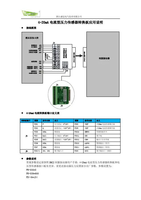
压力传感器使用说明书1211131000/100110141100/11019158167176185194203212221一.仪表选型注1:标准型:仪表出厂前具有继电器输出和电压脉冲输出。
注2:如果仪表选串行通讯口,报警只能选该型号。
二.接线图电源报警2(-)AC90-260V (+)RS484报警3(-)通讯SSR 输出-(+)(D2)24V/20mA +电流互感器输入继电器AC5A 4-20mA 输出+报警1或热电偶PT100第二输出(带PD )安装尺寸(面板安装)1000/10011100/110150145+0.692+0.845+0.692+0.892+0.845+0.6深100mm深100mm深105mm注:为确保安装正确,请参阅英文版手册中的注意事项和警告。
三.功能说明1)输入种类热电偶:K、J、N、S、R、T热电阻:PT100电压:0-50mv,10-50mv电流:0-20mA,4-20mA,0-10mA(电流输入需在输入端并接2.5Ω或5Ω精密电阻)电流互感器输入2)输出输出1:继电器:端子额定电流5A/220VacSSR:24V/20mA电压脉冲DC输出:4-20mA输出2:用报警输出1,通过软件组态改为PD控制功能3)报警功能报警1可以带PD控制,触点电流5A报警2和3触点为常开,可以通过内部跳线改为常闭触点容量为3A/220Vac4)数字通讯(电流环/RS485)如果仪表有1200波特率无源电流环接口,接收二极管在端子8(RX+)和端子9(RX-)传输晶体管端子10(TX+)和(TX-)标准配置(并联到串行口)联接到二极管阻值为1千欧,集电极电阻为100Ω对串联连接,接到二极管阻值为100欧若配置为4线制RS485(1200波特率),输入端为8(RX+)和9(RX-)传输为10(TX+)和11(TX-)[参阅硬件组态]四.显示面板和按键说明A:显示测量值B:显示设定值1)显示过程设定值2)当AL1,AL2,AL3/HB灯闪烁时,设定报警值显示3)当字母“P”前面显示[0-99%]显示主输出功率4)可显示组态参数F:主输出灯,当第一输出动作时该灯亮G:报警输出指示C :功能键“F ”1)F 键用来选择设定值或报警值以便读取和修改设定值,如果未按住F 键,10秒钟后,修改值将自动存贮,同时返回显示过程设定值。
Page 1Copyright © 2021 Sensata Technologies, Inc. Parameter Min Supply Voltage Supply Current (mA)Input Impedance (Volt)Operating Ambient -200°C Relative Humidity 0%Isolation Voltage1kV| IWTXT SERIESWIRELESS 4-20 mA TRANSMITTER WITH Tx SUPPLYInputsFeaturesSPECIFICATIONSThe input types and ranges included below are our standard ones only. Contact Sensata for others.DC Current & Voltage0-20 mA, 4-20 mA, 0-10 mA into 15/30Ω0-1V, 0-10V, 1-5V into 100k Ω/1M ΩAny standard 4-20 mA transmitterThe IWTxT is designed to convert any standard 4-20 mA transmitter into a wireless unit.It works by switching on a supply to the 4-20 mA transmitter, waiting for a suitable settling time and then sending the data to one of Sensata’s standard wireless receiver units.The IWTxT is specially designed to maximise battery life and in a typical application the battery life will exceed 12 months. The data update rate is user selectable to suit the requirement of each measured variable and so maximize battery life.Typical update rates include 1 second, 10 seconds, 60 seconds or 1 hour. The system also features a signal strength reading and time since last transmission which can be remotely monitored.The IWTxT is designed to operate with the IWR range of receivers. The IWR-1 can output a 4-20 mA or 1-5V signal whilst the IWR-PORT can store up to 128 variables for transmission to an industrial Ethernet connection or an RS-232/485 communications link.• Battery powered wireless transmitter• Supplies excitation voltage to 4-20 mA transmitters • Long battery life• Make any transmitter into a wireless transmitter• Complete thermocouple, RTD, Pressure and Level wireless probes are availablePage 2CONTACT USEUROPE+44 (0)1202 897969*********************Cynergy3 Components Ltd.7 Cobham Road,Ferndown Industrial Estate,Wimborne, Dorset,BH21 7PE, United Kingdom USA+1 310 561 8092 / +1 866 258 5057*********************Copyright © 2021 Sensata Technologies, Inc.Sensata Technologies, Inc. (“Sensata”) data sheets are solely intended to assist designers (“Buyers”) who are developing systems that incorporate Sensata products (also referred to herein as “components”). Buyer understands and agrees that Buyer remains responsible for using its independent analysis, evaluation and judgment in designing Buyer’s systems and products. Sensata data sheets have been created using standard laboratory conditions and engineering practices. Sensata has not conducted any testing other than that specifically described in the published documentation for a particular data sheet. Sensata may make corrections, enhancements, improvements and other changes to its data sheets or components without notice.Buyers are authorized to use Sensata data sheets with the Sensata component(s) identified in each particular data sheet. HOWEVER, NO OTHER LICENSE, EXPRESS OR IMPLIED, BY ESTOPPEL OR OTHERWISE TO ANY OTHER SENSATA INTELLECTUAL PROPERTY RIGHT, AND NO LICENSE TO ANY THIRD PARTY TECHNOLOGY OR INTELLECTUAL PROPERTY RIGHT, IS GRANTED HEREIN. SENSATA DATA SHEETS ARE PROVIDED “AS IS”. SENSATA MAKES NO WARRANTIES OR REPRESENTATIONS WITH REGARD TO THE DATA SHEETS OR USE OF THE DATA SHEETS, EXPRESS, IMPLIED OR STATUTORY, INCLUDING ACCURACY OR COMPLETENESS. SENSATA DISCLAIMS ANY WARRANTY OF TITLE AND ANY IMPLIED WARRANTIES OF MERCHANTABILITY, FITNESS FOR A PARTICULAR PURPOSE, QUIET ENJOYMENT, QUIET POSSESSION, AND NON-INFRINGEMENT OF ANY THIRD PARTY INTELLECTUAL PROPERTY RIGHTS WITH REGARD TO SENSATA DATA SHEETS OR USE THEREOF.All products are sold subject to Sensata’s terms and conditions of sale supplied at SENSATA ASSUMES NO LIABILITY FOR APPLICATIONS ASSISTANCE OR THE DESIGN OF BUYERS’ PRODUCTS. BUYER ACKNOWLEDGES AND AGREES THAT IT IS SOLELY RESPONSIBLE FOR COMPLIANCE WITH ALL LEGAL, REGULATORY AND SAFETY-RELATED REQUIREMENTS CONCERNING ITS PRODUCTS, AND ANY USE OF SENSATA COMPONENTS IN ITS APPLICATIONS, NOTWITHSTANDING ANY APPLICATIONS-RELATED INFORMATION OR SUPPORT THAT MAY BE PROVIDED BY SENSATA.Mailing Address: Sensata Technologies, Inc., 529 Pleasant Street, Attleboro, MA 02703, USA.ISO9001CERTIFIED Rev: 01/17/22Made in the UKORDERING OPTIONSInstallation DetailConnection Details1. Battery -ve2. Battery +ve3. Input +ve4.Tx Supply +veInput/Output SignalsDIMENSIONSAll dimensions are in millimeters.*Free download user configuration software here ***Transmission Update Rate 1, 5, 10 and 30 seconds*** Consult installation manual for set-up:- Single channel system is DIL switch configurable- Five channel system requires set-up using “IWR Set” user software。
BA系列电流传感器
1概述
BA系列产品应用电磁感应原理,对电网中的交流电流进行实时测量,采用精密恒流技术和线性温度补偿技术,将其隔离变换为标准的直流信号输出。
采用24伏或12伏安全电压供电,具有过载能力强、高精度、高隔离、高安全性、低功耗等特点,可广泛用于工业自动化领域。
BA系列中剩余电流传感器专用于漏电监控,监测电气线路或电气设备绝缘状态,避免电气线路或电气设备绝缘性能降低引起的事故。
产品符合GB/T13850-1998、GB1208-2006
2型号说明
注:BA50L-AI/I(V)为交流剩余电流传感器
3技术指标
4外形及穿孔尺寸
●BA05、10电流传感器外形及穿孔尺寸
●BA20、50、50L电流传感器外形及穿孔尺寸
5接线示例
如图所示穿心输入Iac,电流输出型传感器的输出为共地电流源,电压输出型传感器的输出为共地电压源。
图中RL是用户负载,输出为电流时,负载≤400Ω(12V供电)或≤800Ω(24V供电);输出为电压时负载≥1kΩ。