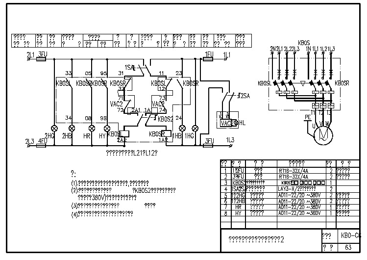
柴油机双电源自动切换柜电路图
- 格式:pdf
- 大小:264.27 KB
- 文档页数:1


柴油发电机组自动控制柜的安装接线方法(总4页)--本页仅作为文档封面,使用时请直接删除即可----内页可以根据需求调整合适字体及大小--柴油发电机组自动控制柜的安装接线方法柴油发电机组如果另外接上一个自动化控制柜,整体机组就转变成自动化柴油发电机组。
自动化柴油发电机组有很多好处。
实现两路电源包括市电与市电、市电与发电或者发电之间)的全自动切换,保证用户的正常用电要求。
电压范围:(400VAC/50HZ容量范围:63A一6300A安全措施:全自动操作,机械、电气双重连锁。
自动化柴油发电机组的工作原理如原供应系统为市电,当市电停电或三相电缺相时,自动切换系统立即切断市电供电并自动启动发电机,发电机启动运行后,3秒钟将电送出,当市电来电正常后,延时30秒停发电机,自动切换到市电供电。
如原供应系统为发电机,当发电机遇故障停机时,自动切换系统立即切断发电机供电并自动转换到市电供电。
主要功能:1、主电路采用ATS型断路器分别进行电气和机械锁联上,配有电动合闸马达,手动合闸等配件,始终只保证一路电源接通负载,工作性能安全可靠,经久耐用。
2、辅助电路分别采用进口时间继电器,中间继电器等先进的辅助电路功能,工作指令运行稳定.分别有自动,手动灵活运用。
3、具有市电恢复功能延时,市电失败确信延时, 开关转换静区延时,发电机组带负载延时,发电机组冷却延时等延时功能用4、该系列产品可与任何品牌远程启动的自动化机组配合使用,可控制发电机的自动启动与停机.自动进行转换供电,从而达到自动保护供电系统稳定的功能,可谓最理想的配电产品.柴油发电机组作为一种必要的备用电源,其结构原理非常复杂,客户在采购柴油发电机组到安全验收过程中各个阶段都要注意一些问题,尤其是在安装过程特别注意,下面就柴油发电机组安装全套流程做详细介绍。
柴油发电机组安装操作流程:准备工作-主机安装-排气、燃油、冷却系统安装-电气设备安装-地线安装-机组接线-机组调试一、准备工作1、材料、设备1) 机组规格、型号应符合设计要求。


柴油发电机组自动化控制电路图柴油发电机组自动化控制电路图⒈引言⑴文档目的本文档旨在提供柴油发电机组自动化控制电路图的详细说明,供相关人员参考和使用。
⑵文档范围本文档覆盖了柴油发电机组自动化控制的主要电路图和相关部件的详细说明。
⒉概述⑴系统概述柴油发电机组自动化控制系统是利用电子技术和自动化控制技术,实现对柴油发电机组的控制、监测和保护。
⑵系统组成柴油发电机组自动化控制系统主要由以下几个部分组成:发电机组控制器、发动机控制器、传感器、执行器、通信模块等。
⒊电路图⑴发电机组控制器电路图发电机组控制器是柴油发电机组自动化控制的核心,其电路图包括主电路和控制回路两部分。
主电路主要包括发电机输出、电池供电、接地保护等部分。
控制回路主要包括控制信号输入、发电机保护、并网控制等部分。
⑵发动机控制器电路图发动机控制器是控制柴油发动机运行的关键,其电路图包括主电路和控制回路两部分。
主电路主要包括电瓶供电、燃油系统、启动系统等部分。
控制回路主要包括传感器信号输入、发动机保护、调速控制等部分。
⑶传感器和执行器电路图传感器和执行器是柴油发电机组自动化控制系统中的重要组成部分,其电路图包括传感器信号输出和执行器控制信号输入两部分。
传感器主要包括温度传感器、压力传感器、速度传感器等。
执行器主要包括电磁阀、电机驱动器等。
⑷通信模块电路图通信模块是柴油发电机组自动化控制系统与外部设备进行通信的接口,其电路图包括通信接口、数据处理和信号转换等部分。
⒋附件本文档涉及的附件详见附件列表。
⒌法律名词及注释⑴法律名词1法律名词1的注释说明。
⑵法律名词2法律名词2的注释说明。
⒍总结本文对柴油发电机组自动化控制电路图进行了详细的说明和解释,涵盖了系统概述、组成部分、各个电路图的细节等内容,为相关人员提供了参考和使用的依据。
柴油发电机组双路电源自动转换柜ATS切(转)换柜详细阐述:一、A TS转换柜简介主要由控制元件及断路器组成,可以手动或自动控制的通断进行送电。
结构简单操作方便,操作人员容易掌握使用方法。
其功能能满足各类用户的需求,开关柜可应用于发电机组进行通断电用,也可以用于其它的配电设备。
二、A TS双电源自动转换开关1.原理双电源自动转换开关是双系统的电源(双电源)利用电磁线圈瞬时的转换,是向负荷供应电力的转换开关。
开关的电磁线圈只在做转换动作时使其通电,动作过后不再通电,由于采用的是平时消耗电力为零的瞬时励磁式机械保持型的结构,开关平时动作过后通过机械性来保持触点接通状态。
2.结构共有三部分组成:①机构部分:由机械保持结构和可动外壳、弹簧、可动板、2组电磁线圈和铁心,微型控制开关,控制电路等构成。
②触点部分:由可动触点,固定触点,端子材料,可曲电线,支撑金属件,触点弹簧,灭弧装置,绝缘材料等构成。
③辅助部分:由辅助触点,绝缘外箱,手动操作棒(可分离)等组成。
3.性能①生产标准:IEC60947-6-1GB/T14048.11JEM 1465②额定电压:AC600V③动作电压:AC220V(其他电压也可制作)④额定电流:30A-4000A⑤极数:4P 3P 2P 1P⑥寿命:机械性25万次以上(30A-400A)5万次以上(500A-4500A)电气性5万次以上(30A-400A)1万次以上(500A-4500A)⑦辅助触点:AC250V 10A三、A TS自动转换控制器A TS控制器是一种集测量显示、控制、三遥等功能为一体自动转换控制器,该控制器有三种型号,分别用于市电与发电、市电与市电或发电与发电等双电源系统的自动转换控制。
·微机控制,全数字化技术;·通过面板按键设定控制器运行方式;·通过LED直观显示ATS的运行状态,控制器运行模式;·通过面板LED数码管显示和按键,设定运行参数;·通过LED显示测量数据,包括电压、频率;·通过RS485通讯口和PC连接(需RS485/RS232接口转换器),可读写、修改所有设定值和数据;·控制器的所有连线都通过针式带锁的端子连接,便于控制器的连线、移动、维修、更换;四、A TS转换开关运行控制参数序号项目预设值数值范围1 市电低电压故障值AC187V AC0~220V2 市电高电压故障值AC242V AC220~286V3 市电高频率故障值52HZ 50-65HZ4 市电低频率故障值48HZ 45-50HZ5 市电故障确认延时时间10秒0-9999秒6 市电供电延时时间10秒0-9999秒7 发电机组起动延时时间15秒0-9999秒8 发电低电压故障值AC187V AC0~220V9 发电高电压故障值AC242V AC220~286V10 发电高频率故障值52HZ 50-65HZ11 发电低频率故障值48HZ 40-50HZ12 发电故障确认延时时间10秒0-9999秒13 发电供电延时时间10秒0-9999秒14 引擎冷却延时时间300秒0-9999秒15 转换开关的类型1型1型2型3型16 通讯地址0(不设)0(不设) 1-128监控功能:包含所有测量数据、控制功能、运行控制参数设定Dual power supply of the diesel generator set automatically converted cabinetATS cut (rpm) for the cabinet to elaborate:An ATS converter cabinet IntroductionOff control components and circuit breakers can be manual or automatic control of power transmission. Simple structure, convenient operation, the operator is easy to grasp. Its functionality to meet the various needs of users, the switchgear can be applied to generating units through power outages with other distribution equipment can also be used.Two, ATS dual power automatic transfer switchA. PrincipleDual power automatic transfer switch is the power of the dual system (dual power) using electromagnetic coil instantaneous conversion, the change-over switch to the load supply of electricity. The electromagnetic coil of the switch so that power only to do the conversion action is no longer energized after action is usually the instantaneous power consumption is zero excitation machinery to maintain the type of structure, switch usually to maintain the mechanical action after contact connected to the state.Two. StructureTotal of three parts:① of part: maintained by the mechanical structure and the movable housing, spring, plate, set of electromagnetic coils and core, micro-control switch, control circuit and other composition.② contact parts: from the moving contact, the composition of the fixed contact terminal material, can Qu wire, metal parts support, contact spring, the interrupter device,insulating materials.③supporting parts: auxiliary contact, insulation outside the box, manual operation rod (separable).3. Performance① production standards:IEC60947-6-1GB/T14048.11The JEM 1465② Rated voltage: up to AC 600V③ Action voltage: AC220V (other voltages can be made)(4) Rated current: 30A-4000A⑤ Number of poles: 4P 3P 2P 1P⑥ life:Mechanical more than 250 000 (30A-400A)50000 (500A-4500A)Electrical resistance of more than 50000 (30A-400A)10000 (500A-4500A)⑦ auxiliary contact: AC250V 10AThird, the ATS automatically converted to the controllerATS controller is a set of measurement control three remote function is automatically converted into one controller, the controller has three models, respectively, for dual-supply of electricity and power generation, electricity and mains or power generation and power generation The system automatically converts control.• Microprocessor control, all-digital technology;Panel buttons to set the controller to run;• through LED intuitive display the operational status of the ATS, the controller mode of operation;Panel LED digital display and buttons to set the operating parameters;• LED display measurement data, including voltage, frequency;• RS485 communication port and a PC connection (required RS485/RS232 interface converter), can read and write, and modify all settings and data;• all connections of the controller are connected by pin locked terminal for easy connection to the controller, move, repair, replacement;, ATS transfer switch operation control parametersNo Item the default range of valuesAn electronic low voltage fault value AC0 is AC187V ~ 220V2 mains voltage failure value AC242V AC220 ~ 286VFault value of the three mains high frequency 52HZ 50-65HZFault value of the four mains low frequency 48HZ 45-50HZ5 mains failure to confirm 0-9999 seconds, 10 seconds of delay time0-9999 seconds, 10 seconds of the delay time of 6 electricity supply7 generator sets starting 0-9999 seconds, 15 seconds of delay time8 generation low voltage fault value AC187V AC0 is ~ 220V9 electricity generation high-voltage fault value AC242V AC220 ~ 286VFault value of 10 power generation high frequency 52HZ 50-65HZFault value of 11 power generation low frequency 48HZ 40-50HZ12 power generation failure to confirm 0-9999 seconds, 10 seconds of delay time0-9999 seconds, 13 power generation and distribution delay time of 10 seconds0-9999 seconds, 14 engine cooling delay time of 300 seconds15 change-over switch type 1 type 1 type 2 and type 316 mailing address 0 (no) 0 (no) 1-128Monitoring function: contains all the measurement data and control functions, operation control parameter settings。