林肯DC1000-NA5自动埋弧焊机维修经验
- 格式:pdf
- 大小:72.93 KB
- 文档页数:3
时代单丝窄间隙埋弧⾃动焊机技术⽅案(林肯配置FOR罗锦2)详解时代单丝窄间隙埋弧⾃动焊机技术⽅案⼀、设备⽤途时代单丝窄间隙埋弧⾃动焊机主要⽤于锅炉、压⼒容器以及核电制造中的中厚板筒体环缝和纵缝的焊接,适⽤于碳钢、低合⾦钢、低温钢以及珠光体耐热钢等多种材料。
⼆、设备特点与传统埋弧焊相⽐,窄间隙埋弧焊的坡⼝窄,焊材填充量⼩,因此焊接效率⾼、成本低。
与窄间隙TIG焊和窄间隙MIG焊相⽐,窄间隙埋弧焊的焊前准备时间较短,坡⼝制备要求不⾼,易于⼯⼈掌握。
焊接热输⼊⼩、热影响区窄、晶粒长⼤区域⼩,因此残余应⼒和焊接变形⼩。
窄间隙埋弧焊属于有规律的多层焊接,每⼀层焊缝对前⾯的焊缝具有回⽕作⽤,细化了焊缝⾦属的晶粒,因此焊接接头的韧性较好。
由于侧壁熔深⼀致,母材⾦属能够均匀地稀释到焊缝中去,因此热影响区的宽度和焊缝⾦属的成分⽐较均匀。
采⽤⾼精度转⾓式焊枪,具有⾃动排焊道功能,可进⾏⼀层两道焊,保证侧壁的可靠融合。
⾼精度、长距离、扫描式激光跟踪系统能够同时进⾏横向和纵向跟踪,确保焊丝端部到坡⼝侧壁的距离以及焊丝⼲伸长度的恒定。
绝对值控制系统,能够实时记忆并存储当前值,具备掉电、出错记忆功能,当设备重启后能记住断电前所有参数。
三、设备组成时代单丝窄间隙埋弧⾃动焊机主要包括以下⼏部分:(1)时代单丝窄间隙埋弧⾃动焊机机头FD11-300NG;(2)时代窄间隙PLC及伺服控制系统;(3)原装进⼝林肯DC-1000埋弧焊接电源、配套NA-3SF送丝机头和NA-3S焊接电源控制器;(4)YS-GHS型焊剂输送回收机(含保温功能和空⽓⼲燥器);(5)时代TZH型重型焊接操作机(具体型号由⽤户选配);(6)时代TR3可调式⾃动防窜滚轮架(具体型号由⽤户选配)。
四、设备使⽤条件和环境设备能在下述环境、⼯件形式及条件下稳定地使⽤:安装位置:室内。
设备应远离剧烈震动、颠簸的场合电源:三相五线制,380V±10% 50Hz±1环境温度:-10~45°C连续⼯作时间:≥24h五、主要技术参数5.1适应⼯件适应⼯件直径:≥1000mm;适应⼯件壁厚:≤300mm ;坡⼝⾓度范围:1~2°(环缝),3~5°(纵缝)坡⼝宽度范围:20~24mm(底部) 5.2适应焊丝焊丝直径: 3.2mm、4.0mm焊丝校直⽅式:双向校直;焊丝校直精度:≤±1mm(焊丝伸出长度为40mm);5.3转⾓式窄间隙焊枪焊枪宽度:12mm;焊枪有效长度:300mm;导电嘴偏⾓:±15゜;每层焊道数:填充焊两道、打底焊⼀道。
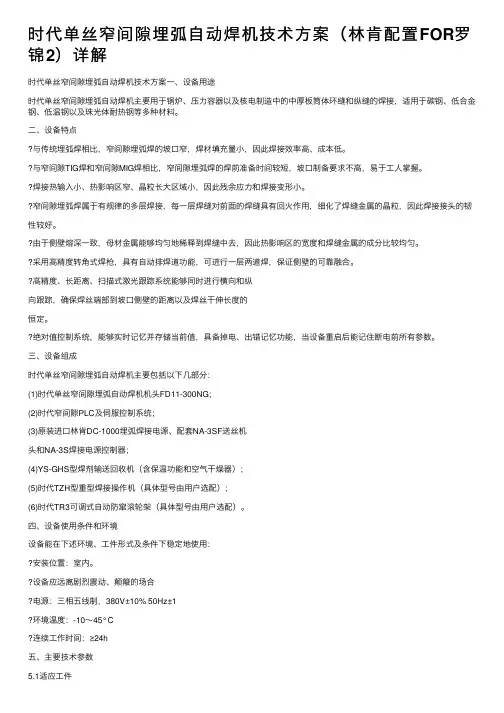
DC—1000埋弧自动焊技术协议甲方(需方)博世热力技术(武汉)有限公司乙方(供方)武汉肯比焊接技术有限公司关于甲方订购1台林肯DC-1000埋弧焊电源,事宜,甲乙双方本着平等互利的原则,就本设备技术问题达成以下协议:1. 设备名称:埋弧自动焊接系统2. 设备规格型号:根据用户对焊接的要求及工件情况,设备配置如下:林肯DC-1000埋弧焊电源1台LT-7轨道式自动送丝机1套3. 设备技术条件3.1 设备用途:埋弧焊自动焊接3.2 主要技术参数:3.2.1 详细说明加工对象的要求、范围3.2.2 设备的详细技术参数(含遵循的技术标准/规范)(一)林肯DC--1000埋弧焊电源额定工作电流1000A额定负载持续率100%输入电源AC三相380V±10%50HZ±2%输出电流范围150——1300A空载电压Max75V接头开关NA---3电源电压调节范围16——46V(二)LT-7轨道式自动送机产品名称LT-7轨道式输入电源115V交流50/60HZ额定输出电流/暂载率600A/100%1100A/100%送丝速度范围 2.5~10.2m/min (100~400英寸/分)行走速度范围0.2~1.8m/min (6~70英寸/分)垂直机头升降调节范围12.7~127mm (1/2~5英寸/分)焊丝尺寸范围 2.4~4.8mm (3/32~3/16英寸)任一侧焊接角与垂直方向最大夹角50°制动角与垂直方向最大夹角30°3.2.3 设备其它技术指标(无)3.3 设备的组成及说明(一)林肯DC--1000埋弧焊电源1、美国林肯DC—1000整流器为六相可控硅半桥弧焊整流器,采用单旋钮电位器控制,应用于半自动和全自动焊接,电弧特性为平特性和降特性两种,可实现单一电源多种用途焊接。
2、DC---1000弧焊整流器适应自动埋弧焊电源,也可做手工弧焊电源、MIG焊、药芯焊丝焊,并且也可以做碳棒直径高达5/8英寸(15.9mm)的碳弧气刨电源。
埋弧自动焊小车常见故障原因分析及改进措施摘要:介绍了埋弧自动焊在铁路货车中梁工序生产中的重要作用,分析了焊丝与导电嘴堵的问题,并且对此问题进行了解决并于运用。
关键词:埋弧焊导电嘴焊丝导电杆一、概述埋弧自动焊又称焊机层下电弧焊,它于手工电弧焊的区别,主要表现在焊接过程中引燃电弧和电极金属-焊丝的送进,与沿焊接方向的移动全部都是用机械自动进行的。
埋弧自动焊与手工电弧焊比较有以下优点:1、焊接生产率高2、焊缝质量好3、节省焊接材料及电能4、焊接变形小5、改善了劳动条件基于以上各优点,货车分厂的中梁封底焊和中梁正面焊都采用了埋弧自动焊,不仅大量节省了人力资源,而且使中梁焊缝成型质量得到了良好的保障。
二、埋弧焊设备组成它主要由焊接电源、焊丝盘和焊丝送进机构、焊剂送进装置、行走小车等组成,由于自动焊是把焊丝盘、焊丝送进、焊剂送进、焊接控制(操作盘)、行走小车集成为一体,因此也把部分称作焊接机以区别于焊接电源。
货车分厂用于中梁正面焊接的埋弧自动焊为唐山开元产的ZD5-1000型焊机,焊丝为长春时代焊接材料有限责任公司生产的H08A型焊丝。
如图1。
而影响生产造成故障问题的部位却在导电杆与导电嘴的配合处。
如图2。
三、问题的因素有31、货车分厂运进的焊丝经焊丝机缠绕进焊丝盘中,然后送往中梁埋弧自动焊进行使用。
前期出现的问题是,由于货车分厂的焊丝机原理与埋弧自动焊机的自动送丝机构相似,是由电机带动两个导丝轮通过摩擦作用将焊丝缠绕在焊丝盘中。
长期的使用,使导丝轮表面光滑程度大大降低,在压力作用下,使焊丝表面被划伤,使表面凹凸不平。
当焊丝通过导电嘴时,由于导电杆与导电嘴结合为偏心结合,焊丝往往在圆锥与圆柱过渡边缘被卡住。
此时,焊丝在此处将出现被卡出的毛刺。
2、焊丝及导电嘴的因素货车分厂采用的是牌号为H08A的埋弧焊丝,由于焊丝为Φ3mm,但大部分都在Φ3.05mm以上,更有甚者达到了Φ3.10mm。
这是导致导电嘴经常堵的原因之一。
林肯DC1000焊机中文说明书IDEALARC DC-1000 IM420-A配合以下代码的机器使用:9919-9925 和10293注意安全,重在自己林肯电弧焊接和切割设备是以安全第一为准则进行设计和制造的。
但是,正确安装和操作更有利于保障您的人身安全。
禁止在没有通读此手册和所包含的安全规章情况下安装,使用或维修此设备。
更重要的是,客户在进行上述操作之前应考虑得当。
1安全!警告请确保所有的安装,操作,维护以及修理过程均由合格人员执行。
1.h. 为了防止烫伤,当发动机仍然热时严禁打开散热器压力盖!内燃机类设备1.a.在排除故障和维修前,应关闭发动机,除非维修工作需要它运转。
1.b.在开放,通风良好的地方操作发动机,或者将废气排到室外。
1.c.禁止在焊接电弧附近或当发动机运转时添加燃料。
在添加燃料前应使发动机停止转动并使其冷却,防止溅出的燃料挥发与热态的发动机部件接触而燃烧。
若燃料溅出,需擦净后才能启动发动机。
1.d.应使所有设备的安全防护罩,盖子和装置在适当位置并检修正常。
当起动,使用或维修设备时,手,头发,衣物和工具应远离V型皮带,齿轮,风扇和所有其它运动部件。
1.e.有些情况,需要拆除防护罩进行必要的维修。
切记只有在必要时才能拆下防护罩并且当维修结束后请迅速将其复原。
在运动部件附近工作时要格外小心。
1.f.禁止用手接近风扇。
当发动机工作时,禁止不顾调速器或空转轮而强行推动节气阀控制杆。
1.g.在维修时,当转动发动机或焊接电源时,为了防止意外起动汽油发电机,请断开火花塞接线,点火分配器顶盖或电磁发动机接线及其它。
电磁场对人体有害2.a.流过任何导体的电流会产生电磁场(EMF) 。
焊接电流在焊接电缆和焊机附近将产生EMF。
2.b. 在EMF区内心脏起搏器会受到干扰,带有心脏起搏器的焊工在焊接前应向医生咨询。
2.c.在焊接时暴露于EMF区情况下将对身体健康产生其它未知影响。
2.d. 所有焊工需执行下述步骤以减小焊接回路EMF区的暴露程度。
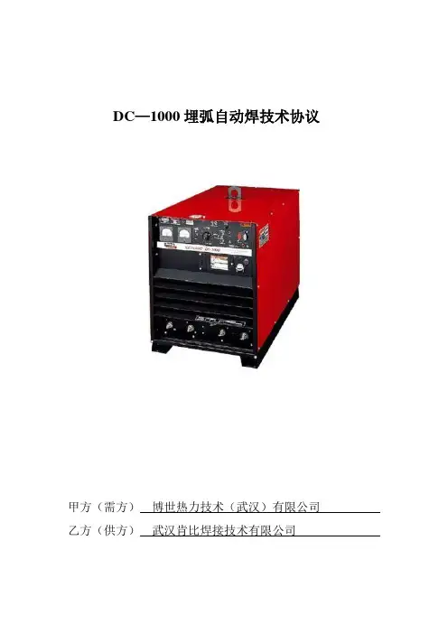
MZ-1000自动埋弧焊机的维修一、概述MZ-1000自动埋弧焊机是本公司引进国外先进技术,在消化吸收并改进后而发展起来的一种高品质自动焊机.该焊机主要用于大中型碳钢、合金钢、不锈钢的焊接,在钢结构厂房、造船、锅炉、化工容器、桥梁、起重机械及冶金机械等制造业中应用最为广泛,该机具有如下特点:1.采用特殊引弧,引弧成功率极高。
2.电源波动补偿电路在电压波动10%时仍能保持输出电压恒定和电流稳定,使焊接质量得以保证。
3.保护电路完善,使焊机可靠性大大提高。
4.负载持续率为100%,满足高强度的焊接。
5. 1台焊机4种功能自动埋弧焊碳弧气刨实心、药芯气保焊直流手弧焊二、主要技术参数技术参数 MZ-630 MZ-1000 MZ-1250额定输入电压 3-380V 3-380V 3-380V额定频率 50/60Hz 50/60Hz 50/60Hz额定输入容量 57 kVA 98 KVA 110 kVA额定输入电流 68A 112A 140A电流调节范围 130A-630A 200A-1000A 250A-1250A负载持续率 100% 100% 100%最高空载电压 69V 72V 72V适用焊丝直径Ф3 Ф4 Ф3 Ф4 Ф5 Ф3 Ф4 Ф5行走速度 20-170cm/min 20-170cm/min 20-170cm/min送丝速度 20-200cm/min 20-200cm/min 20-200cm/min电源外型 970X470X690mm 970X570X690mm 970X570X690mm电源重量 200 kg 400 kg 420 kg小车重量 50 kg 50 kg 50 kg三、保养与故障修理5.1 保养(1)定期检查•为了安全、有效的使用电焊机,请注意进行定期保养与检查。
•日常的注意事项A有无异常的振动、响声、臭味B电缆部位有无异常发热。
C在电源打开时,风扇、是否顺利地转动。
D电缆的连接、绝缘方法是否有误E电缆是否有即将短线的地方。

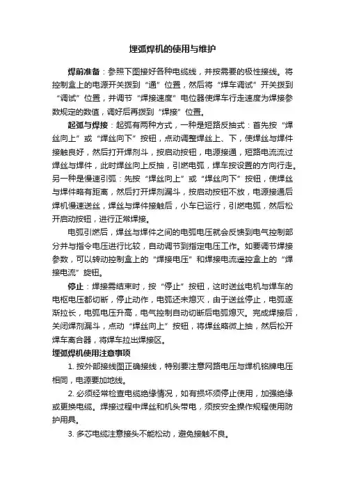
埋弧焊机的使用与维护焊前准备:参照下图接好各种电缆线,并按需要的极性接线。
将控制盒上的电源开关拨到“通”位置,然后将“焊车调试”开关拨到“调试”位置,并调节“焊接速度”电位器使焊车行走速度为焊接参数规定的数值,调好后再拨到“焊接”位置。
起弧与焊接:起弧有两种方式,一种是短路反抽式:首先按“焊丝向上”或“焊丝向下”按钮,点动调整焊丝上、下,使焊丝与焊件接触良好,然后打开焊剂斗,按启动按钮,电源接通,短路电流流过焊丝与焊件,此时焊丝向上反抽,引燃电弧,焊车按设置的方向行走。
另一种是慢速引弧:先按“焊丝向上”或“焊丝向下”按钮,使焊丝与焊件略有距离,然后打开焊剂漏斗,按启动按钮不放,电源接通后焊机慢速送丝,焊丝与焊件接触后,小车已运行,引燃电弧,然后松开启动按钮,进行正常焊接。
电弧引燃后,焊丝与焊件之间的电弧电压就会反馈到电气控制部分并与指令电压进行比较,自动调节到指定电压工作。
如要调节焊接参数,可以转动控制盒上的“焊接电压”和焊接电流遥控盒上的“焊接电流”旋钮。
停止:焊接需结束时,按“停止”按钮,这时送丝电机与焊车的电枢电压都切断,停止动作,电弧还未熄灭,由于送丝停止,电弧逐渐拉长,电弧电压升高,电气控制自动切断后电弧熄灭。
完成焊接后,关闭焊剂漏斗,点动“焊丝向上”按钮,将焊丝略微上抽,然后松开焊车离合器,将焊车拉出焊接区。
埋弧焊机使用注意事项1.按外部接线图正确接线,特别要注意网路电压与焊机铭牌电压相同,电源要加地线。
2.必须经常检查电缆绝缘情况,如有损坏须停止使用,加强绝缘或更换电缆。
焊接过程中焊丝和机头带电,须按安全操作规程使用防护用具。
3.多芯电缆注意接头不能松动,避免接触不良。
4.定期检查控制线路中的电器元件,对损坏或触点烧毛的进行更换。
5.定期检查送丝轮的磨损情况,如发现显著磨损时,应进行更换。
6.定期检查和更换送丝机构和焊车减速箱内的润滑油。
7.必须经常检查导电嘴的磨损情况,若磨损须进行更换。
林肯DC-1500直流电焊机大修经验总结
高宝明;黄雄飞;李国锋;金江
【期刊名称】《焊管》
【年(卷),期】2005(028)006
【摘要】叙述了美国林肯DC-1500直流电焊机变压器一次线圈严重烧坏后的检查、测试、修理及试验方法.寻求较经济的大修方案,努力使修理后的电焊机达到原有技术性能,以满足钢管生产工艺需要.
【总页数】4页(P52-55)
【作者】高宝明;黄雄飞;李国锋;金江
【作者单位】中石化江汉石油管理局沙市钢管厂,湖北,荆州,434001;中石化江汉石油管理局沙市钢管厂,湖北,荆州,434001;中石化江汉石油管理局沙市钢管厂,湖北,荆州,434001;中石化江汉石油管理局沙市钢管厂,湖北,荆州,434001
【正文语种】中文
【中图分类】TG434.1
【相关文献】
1.林肯电气公司胡总一行到访成都电焊机研究所 [J],
2.山区高速公路大修工程成功经验总结 [J], 胡亮
3.林肯城市发动机大修后不能起动 [J], 刘彰武
4.林肯DC-1500型自动埋弧焊机故障排除 [J], 付辉
5.4000KW高压同步电动机大修经验总结 [J], 吴丽华
因版权原因,仅展示原文概要,查看原文内容请购买。
L T -7 TRACTOR TROUBLESHOOTINGIM279-TSJUNE 1995Safety Depends on YouLincoln arc welding and cutting equipment is designed and built with safety in mind. However, your overall safety can be increased by proper installation ... and thought-ful operation on your part.DO NOT INSTALL, OPERATE OR REPAIR THIS EQUIPMENT WITHOUT READING THIS MAN-UAL AND THE SAFETY PRE-CAUTIONS CONTAINED THROUGHOUT.And, most importantly, think before you act and be careful.Mar ‘95TABL E OF CONTENTSivivGENERAL DESCRIPTIONThe LT-7 tractor is a compact, lightweight, DC, single arc tractor.It is capable of operating with 3/32”through 3/16”electrode with a current carrying capacity of 1000 amps.The LT-7 has a travel range from 6 to 70 inches per minute.FIGURE E.1 - 115VAC INPUT POWER CIRCUITSINPUT POWER CIRCUITSThe LT7 is powered by 115VAC which is usually sup-plied from the welding power source.The 115VAC isapplied to the travel board.This voltage is also coupledto the control box circuitry through the on/off powerswitch and a 3 amp circuit breaker.The input power isthen applied to the the variable voltage board and,through resistor R1, to the control board.The 115VACis rectified and regulated by the control board whichsupplies 24VDC to the logic board.Upon receiving commands from the user operated switches or potentiomenters the logic board sends the appropriate signal to the control board which then dri-ves the wire feed motor to the correct speed and direc-tion.When the start signal is received by the control board the power source contact relay(1CR) is ener-gized as well as the travel relay(2CR) and the wire drive motor.When weld current closes reed switch 3CR the logic board directs the control board to change the wire feed speed from the preset inch speed to the welding feed speed set by the wire speed control potentiome-ter.Reed switch 4CR protects the internal grounding wire circuitry.In the event that abnormally high currentwas to flow in the grounding lead system the 4CR reed switch would close, signaling the logic board to stop the welding procedure.The inch up switch, which is cou-pled directly to the control board, dictates that the wire drive motor reverse direction and back the electrode wire away from the work piece.T ravel speed, direction and mode (either manual or auto) are determined by the settings of the three con-trols connected to the travel board.The travel board then applies the correct voltage and polarity to the trav-el motor to satisfy the control settings.CONTROL,LOGIC AND TRAVEL BOARDSFIGURE E.2 - CONTROL LOGIC AND TRAVEL BOARDSArc voltage is monitored by the voltmeter and variable voltage board.When the LT7 tractor is being operated in the constant current mode the variable voltage board is essential in the control of the wire feed speed. As the arc length changes the arc voltage will also change.The variable voltage board recognizes this change and signals the logic board to either increase or decrease the wire feed speed.This function is neces-sary to maintain a constant electrode arc length and a stable and high quality weld.The variable voltage board also generates a low volt-age which is applied to the electrode during the inch down mode.When the electrode makes contact with the work piece this low voltage is “loaded down”thus signaling the control circuitry to stop the wire feed motor.This feature allows the operator to utilize “work touch sensing”.FIGURE E.3 - VARIABLE VOLT AGE BOARD VARIABLE VOL TAGE BOARDA-4NOTES A-4If for any reason you do not understand the test procedures or are unable to perform the tests/repairs safely, contact the Lincoln Electric Service Department for technical troubleshooting assistance before you proceed.Call 216-383-2531 or 1-800-833-9353.Service and Repair should only be performed by L incoln Electric Factory Trained Personnel.Unauthorized repairs performed on this equipment may result in danger to the technician and machine operator and will invalidate your factory warranty.For your safety and to avoid Electrical Shock,please observe all safety notes and precautions detailed throughout this manual.This Troubleshooting Guide is provided to help you locate and repair possible machine malfunctions.Simply follow the three step procedure below.Step 1.LOCATE PROBLEM (SYMPTOM).Look under the column labeled “PROBLEM (SYMPTOMS)”.This column describes possible symptoms that the machinery may exhibit.Find the listing that best describes the symptom that the machine is exhibiting.Symptoms are grouped according to:function problems and travel problems.Step 2.PERFORM EXTERNAL TESTS.The second column labeled “FIELD COURSE OF ACTION”lists the basic possibilities that may contribute to the machine symptom.Perform these tests/checks in the order listed.Step 3.PERFORM COMPONENT TESTS.The last column labeled “RECOMMENDED SHOP COURSE OF ACTION”lists the most likely components that may have failed in your machine.It also specifies the appropriate test procedure to verify that the subject component is either bad or good.If there are a number of possible components,check the components in the order listed to eliminate one possibility at a time until you locate the cause of your problem.All the necessary test specifications and repair procedures are described in detailfollowing the troubleshooting guide.All electrical test points, terminal strips,junctions, etc., can be found on the electrical wiring diagrams and schematicsin the Electrical Diagram Section.How To Use Troubleshooting GuideT able B.1 P.C.Board Status LightsON* INDICA TES LIGHT IS DIMT able B.2 P.C.Board Status Light DefinitionsB-22TROUBL ESHOOTING AND REPAIR B-22 ArrayFIGURE B.1 Logic P.C.Board LED LocationsFIGURE B.3 Control P.C.Board LED LocationsB-23NOTES B-231.Remove the wire feed motor connector from the LT7 control box.ing the ohmmeter measure the motor resistances per Table B.3.Also see Figure B.43.If the motor resistance test is good pro-ceed to the Motor Applied Voltage T est.MOTOR APPLIED VOLTAGE TEST 1.Carefully connect the 110VDC supply (SUPPL Y TURNED OFF) to pins C and D on the motor connector.2.Carefully connect the variable 0 to 90VDC supply (SUPPL Y TURNED OFF) to pins A and B on the motor connector.(See T able B.3)3.Apply field voltage first(pins C and D) to the motor.Then slowly apply the arma-ture voltage on pins A and B.(See T able B.3)4.The motor should run and the speed should vary with changes to the armature voltage.5.If the motor does NOT run and change speed correctly the motor or gear box may be faulty.6.To stop motor REMOVE ARMATURE VOLT AGE FIRST .(Pins A and B)T ABLE B.3TEST PROCEDUREWIRE DRIVE MOTOR TEST (continued)FIGURE B.4 - Wire Drive Motor Connector PinsTEST PROCEDURE1.Remove the travel motor connector fromthe LT7 control box.ing the ohmmeter measure the motorresistances per Table B.4.Also see Figures B.5.and B.6*3.If the motor resistance test is good pro-ceed to the Motor Applied Voltage T est. MOTOR APPLIED VOLTAGE TEST1.*Carefully connect the 110VDC supply(SUPPL Y TURNED OFF) to pins C and D on the travel motor connector.See FigureB.62.Carefully connect the variable 0 to 90VDCsupply (SUPPL Y TURNED OFF) to pins A and B on the travel motor connector.3.*Apply field voltage first (pins C and D) tothe motor.See Figure B.6 and T able B.44.Slowly apply the armature voltage on pinsA and B.(See T able B.4)5.The motor should run and the speedshould vary with changes to the armature voltage.6.If the travel motor does NOT run andchange speed correctly the motor or gear box may be faulty.7.*To stop motor REMOVE ARMATUREVOLT AGE FIRST.(Pins A and B)*DENOTES OLDER UNITS WITH FIELD WINDING*DENOTES OLDER UNITS WITH FIELD WINDINGFIGURE B.5 T ravel Motor Connector PinsFIGURE B.6 T ravel Motor Connector Pins (OlderUnits with Powered Field.)B-29NOTES B-29MOTOR REMOVAL PROCEDURE:1.Remove the wire drive motor cable fromthe LT7 control box.ing the 1/2”wrench remove the boltholding the flux hopper(if used) to the bumper handle assembly.e the large slot head screwdriver toremove the two slot head screws holding the bumper handle assembly to the gear box housing.e the 5/32”Allen type wrench to removethe socket head cap screw from the gear box housing and motor end bracket.5.Locate and remove the four small slothead screws holding the inspection cover plate to the gear box housing.Note place-ment of rubber gasket and cable strain clamp.6.Locate and remove the two socket headcap screws mounting the motor to the gear box housing.Note:The inspection cover plate has to be remove (Step #5) to gain access to the two socket head cap screws.7.Carefully remove the motor(with piniongear) from the gear box assembly.MOTOR REPLACEMENT PROCEDURE: 1.Carefully install the replacement motor(with pinion gear) and mount to the gear box housing using the two socket head caps screws.ing the four small slot head screwsinstall the inspection cover plate along with the rubber gasket and cable clamp.3.Install the bumper handle assembly withthe socket head cap screw and the two larger slot head screws.4.Install the flux hopper (if used) to thebumper handle assembly and secure with the hex head bolt.5.Attach the wire drive motor cable to theLT7 control box receptacle.WIRE DRIVE MOTOR REMOVAL PROCEDURE (continued)CONNECTION SCHEMATIC - M15342T h i s d i a g r a m i s p r o v i d e d f o r r e f e r e n c e o n l y .I t m a y n o t b e t o t a l l y a p p l i c a b l e t o a l l m a c h i n e c o d e s .CONTROL BOX WIRING DIAGRAM- L7460It may not be totally applicable to all machine codes.C-3NOTES C-3World's Leader in Welding and Cutting Products Premier Manufacturer of Industrial Motors。
林肯焊机NA-5控制器维修备忘录
9月11日上午接实验室电话称林肯焊机带极埋伏坏,经检查焊机只能起弧不能正常焊接工作,经与厂家联系来人检查分析,更换控制器内各种电路板块仍没有发现问题,与厂家协商回去调图纸研究,在之后的几天了通过不断的咨询和联系,上网查资料,终于发现控制箱内的元器件CR4有问题,更换丝极控制箱内CR4设备能够焊接了,但正常焊接指示灯不亮,且焊接结果成型不好,表面不均匀,还有程序板也有问题,在厂家的大力协助线,找到原因,将CR4固定好,DC1000控制放在远程控制上,问题解除。
故障1 只能起弧不能正常焊接工作,元器件CR4有问题,需更换。
故障2不能进入焊接状态,元器件CR4没有固定好,固定。
故障3 影响焊接过程,DC1000控制没有放在远程控制上,调整。
注(1):元器件CR4 为舌黄管继电器,具体型号不知,厂家无备货,需从美国进口,时间至少1个月。
(2):鉴于没有配件的情况,实验室工作人员建议将带极控制器坏的CR4换到丝极上试试,没问题,两套设备都能运行了。
(问题可能出在丝极实验时用一台DC1000焊机电流小,带极实验时并联两台DC1000焊机电流大,而带极CR4由于疲劳损耗只能在电流小的丝极焊接实验中使用。
(3):有条件尽量更换新的CR4.
2012-9-20 张玉成。
Publication E9.30 | Issue D a te 08/10 Web Update 01/12© Lincoln Global, Inc. All Rights Reserved.SUBMERGED ARC & AUTOMATIC EQUIPMENTProcessesFlux-Cored, Submerged Arc Product Number K356-2See back for complete specs Input Power115 VAC 50/60 Hz Wire Size Range.035 - 7/32 in. (0.9 - 5.6 mm)Wire Feed Speed Range 25-775 ipm(0.6-16.5 m/min)Net Weight/Dimensions (H x W x D)41 lbs. (18.6 kg)12.75 x 18.5 x 22.25 in.(324 x 470 x 565 mm)PH: +1.216-481-8100 • Shown: K356-2NA-5[ 2]|NA-51.Control Power Switch –Turns wire feeder input power on and off. Also serves as an emergency stop switch.2.Pilot Light –Shows when the electrode is "hot".3.Inch Pushbuttons –Feed electrode up and down when not welding.4.Start and Stop Pushbuttons –Control welding cycles.5.Meter Value Pushbutton –Monitor either the preset values or the actual values.6.Timer Control –For burnback and/or wire react time.7.Crater Module (optional) –Controls procedure for anadjustable period of time to regulate bead size or fill craters at the end of the weld.8.Weld Timer (optional) –Eliminates the need to press stop pushbutton.9.Lockable Cover –Lockout procedure controls when necessary.10.Digital Display –Monitor wire feed speed and voltage on separate meters.11.Start Module (optional) –Controls penetration, bead size, or other factors for an adjustable time at the start of the weld.12.WFS and Voltage Preset Controls –Preset wire feed speed and voltage prior to and during welding. These controlseliminate returning to the power source for routine procedure changes.13.Travel Switch –Controls the travel mechanism for automatic starting and stopping when welding, travel without welding during setup and travel off.12345678910111213K299 Reel and Mounting – Order separately.NA-5 Control K356-2DC Power Source –Constant Voltage type with on-off control of power source output.4 ft. (1.2 m) Motor Cord –Included with K346.4 ft. (1.2 m) Electrode CablesContact Nozzle (optional)K335-26 Extension – Motor, flux hopper and electrode cables. Optional when more than 4 ft. (1.2 m) is required.Work Cable – Two or more 4/0NA-5S and NA-5SFFor Submerged Arc WeldingTwo 4/0 electrode cables and the multi-conductor control cable.Flux Hopper –Included with K346.Solid Wire Straightener Head4 ft. (1.2 m) Flux Hopper Cord –Included with K346.REQUIRED EQUIPMENTSolenoid AssemblyValve to automatically control water flow when using cooling attachment on K148 contact assemblies. Can also be used to control gas. Order K223Starting or Crater Module Permits additional settings of wire feed speed and voltage for an adjustable period of time (10 seconds max). Can be used for either a starting procedure or a crater fill procedure. If both are required, two assemblies must be ordered.Order K334Remote Interface ModulePermits remote operation of theNA-5 Inch Up, Inch Down, Start andStop Functions by either of thefollowing user-supplied externalsignals and provides electricalisolation of the NA-5 control circuitryfrom these signals:-SwitchesMomentary closure of contactsrated for 24 volts,5 milliamperes, DC.-24 Volt SignalsMomentary application of 24volt ±10% AC or DC signalcapable of 5 milliamperessteady state. (.15 amp peakcapacitive in rush) per input.This module can be used withall codes of NA-5 Controls andreplaces the earlier K336Remote Pushbutton InterfaceModule, which provided for onlyexternal switch closure signals.Order K336Weld Timer ModulePermits setting of weld time for anadjustable period of time. Eliminatesneed to press stop pushbutton. Thetimer unit is adjustable from 0.00 -9.99 seconds.Order K337-10Control To Head ExtensionCable AssemblyThe standard head is equipped withcables which permit the head to bemounted up to four feet from thecontrols. "F" models, however, donot include electrode cables. Whenthe head is mounted further awayfrom the control, extension cableassemblies must be purchased. Forthe NA-5S head: Includes motor,tachometer, and flux valve leadextensions with polarized plugs andelectrode. 26 ft. length.Order K335-26Recommended for the NA-5N, andSF heads. It is the same as the K335without the flux valve lead extension.Available in 46 ft. lengths.Order K338-46Mounting KitFor use if the NA-5 control box is tobe mounted on the carriage.Order T14469SINGLE ELECTRODESubmerged Arc Contact NozzleAssembly for 3/32 in. (2.4 mm),1/8 in. (3.2 mm) and 5/32 in.(4.0 mm) electrodes.For 5/64 in. (2.0 mm), 3/16 in.(4.8 mm) or 7/32 in. (5.6 mm) sizes,order additional appropriate KP1962tips. Outer flux cone gives full fluxcoverage with minimumconsumption.(Rated up to 650 amps.)Order K231-1K231 nozzle tipsDesigned for long life.OrderKP1962-1B1for 1/8 in. (3.2mm) wireKP1962-2B1for 3/16 in. (4.8 mm) wireKP1962-3B1for 3/32 in. (2.4 mm) wireKP1962-4B1for 5/32 in. (4.0 mm) wireKP1962-5B1for 7/32 in. (5.6 mm) wireKP2082-2B1for 5/64 in. (2.0 mm) wireNarrow Gap Deep Grove NozzleFor single arc 3/32 in. (2.4 mm)diameter wire welding on thickwalled steel plate with nearlyparallel-sided, narrow gap jointpreparations.Order K386Contact Jaw AssemblySingle arc contact jawassembly for 1/8-7/32 in.(3.2-5.6 mm) diameter wire. Ruggedcontact jaws for maximum life atcurrents over 600 amps.Order K226RTWINARC®Tiny Twinarc®Wire StraightenerStraightens wire diameters .045 thru3/32 in. (1.2 thru 2.4 mm).Particularly valuable on longerelectrical stickout procedures.Order K281Tiny Twinarc®Feeds two 1/16, 5/64, or 3/32 in.(1.6, 2.0, or 2.4 mm) electrodes forhigh speed submerged arc welds onthin gauge (1.89 mm) to heavy plate.Includes contact nozzle, wire guides,drive rolls and guides, and a secondwire reel and mounting bracket.Order K129-1/16K129-5/64K129-3/32Large Wire Twinarc®Contact AssembliesFeeds two 5/64 in. (2.0 mm),3/32 in. (2.4 mm) or 1/8 in. (3.2 mm)wires for submerged arc weldingon "Fast-Fill" joints or hardfacingbeads.Order K225GENERAL OPTIONSConcentric FluxCone AssemblyFor use with K148B, Positive ContactNozzle Assembly. Gives concentricflux coverage around the electrode.Order K285Positive Contact AssemblyFor single arc welding at highcurrents (optional T12928 watercooling attachment recommendedwhen welding over 600 amps).Order K148A(for 3/32 to 1/8 in. wire)Order K148B(for 5/32 to 3/16 in. wire)ESO (Extended Stick-Out)ExtensionLinc-Fill long stickoutextension for K148A Single ArcPositive Contact Nozzle Assembly.Required for long stickout technique.Order K149-5/325 in. Nozzle ExtensionExtends the wire for subarc nozzlesby 5 inches [up to 1/4 in. (6.4 mm)diameter wire].Order KP2721-1Horizontal Head AdjusterProvides crank adjustment of headposition. Has 2 in. (51 mm)horizontal travel.Order K96Vertical Lift AdjusterProvides 4 in. (102 mm) hand crankadjustment of vertical head position.It also includes up to 3-3/4 in.(95.2 mm) in-and-out horizontaladjustment with stops that can bepreset for simple repetition of thesame adjustment.Order K29SpreadArc OscillatorOscillates head across the line oftravel. Calibrated dwell time andoscillation speed controls permit theSpreadArc to cover large areasquickly with smooth beads ofminimum admixture.Order K278-1TC-3 Self-PropelledTravel CarriageThe TC-3 travel carriage allows themounting of up to two feed heads/controllers and wire reels to a beamfor basic hard automationinstallations.Order K325 HCS(for 5-75 ipm)NA-5| [ 3]Automatic Flux Hopper Assembly Flux Hopper for MAXsa ™29 Heads (included standard on the MAXsa ™22 Heads). Order K219Wire Reel Assembly for 50-60 lb. CoilsAccommodates 50 lb. (22.7 kg) or 60 lb. (27.2 kg) coils of wire on automatic wire feeders. The unit includes a wire reel mountingspindle and braking system. Cannot be used with K2462-1.Order K299Tandem ReelsTwo Wire Reel Mounting for TC-3. Order K390Tandem Arc FrameworkProvides mountings with desired positioning adjustments for two standard Automatic Wire Feed Heads. Includes insulation and hardware to permit direct mounting to a high capacity TC-3 Carriage, or to the user's gantry or fixture for either direction of travel.Order K387Flux HopperTandem Arc Flux Hopper for K387 mountings. Order K389Wire Straightener (Subarc) up to 7/32 in. (5.6 mm)Includes a three roll wire straightener with adjustable pressure. (1 included with each tractor and MAXsa ™Feed Head.) Order K1733-5(1)For the K347 Head, order the K338 extension.(2)For gear ratios shown.C U S T O M E R A S S I S T A N C E P O L I C YThe business of The Lincoln Electric Company is manufacturing and selling high quality welding equipment, consumables, and cutting equipment. Our challenge is to meet the needs of our customers and to exceed their expectations. Onoccasion, purchasers may ask Lincoln Electric for information or advice about their use of our products. Our employees respond to inquiries to the best of their ability based on information provided to them by the customers and the knowledge they may have concerning the application. Our employees, however, are not in a position to verify the information provided or to evaluate the engineering requirements for the particular weldment. Accordingly, Lincoln Electric does not warrant or guarantee or assume any liability with respect to such information or advice. Moreover, the provision of such information or advice does not create, expand, or alter any warranty on our products. Any express or implied warranty that might arise from the information or advice, including any implied warranty of merchantability or any warranty of fitness for any customers’ particular purpose is specifically disclaimed.Lincoln Electric is a responsive manufacturer, but the selection and use of specific products sold by Lincoln Electric is solely within the control of, and remains the sole responsibility of the customer. Many variables beyond the control of Lincoln Electric affect the results obtained in applying these types of fabrication methods and service requirements.Subject to Change – This information is accurate to the best of our knowledge at the time of printing. Please refer to for any updated information.For best welding results with Lincoln Electric equipment, always use Lincoln Electric consumables. Visit for more details.。
Ⅰ.机械安装1.机头安装安装应牢固以防起弧时机头移动,注意机头与工作电缆应与地绝缘。
根据需要,可装在垂直调节器/水平调节器/行走小车上,所定的机头出厂前根据用户的订购模式安装送丝比率,当改变焊丝直径时需改变送丝轮和导向管。
对不同直径的焊丝需调节随动轮压力调节螺丝,焊丝分两档0.9-2.4mm和2.4-5.6mm。
根据需要调节,对较软的焊丝,压力宜小一点。
出厂时送丝轮设为正转(如图所示方向),但安装板可转动180º,并对换校直器和导电杆,送丝轮转动方向通过改变控制箱内接线上626,627号线来实现。
一般用25kg送丝盘。
NA-3S/NA-4/NA-3SF出厂时所装焊丝校直器的焊丝直径大于2.4mm以上。
机头安装好后,通过校直器和送丝导向管安装焊丝(其入口处为倒圆)而出丝导向管入口处为倒角)。
2.控制箱安装控制箱在标准行走小车或其它的机架上,当装在其它机架上时,打开控制箱后盖,按照控制箱底板上的安装孔固定控制箱。
3.导电杆组件国内一般常用K231和K226●K231导电杆组件:一般用于600A,更高电流可能引起导电嘴磨损加快。
适用于Ф2.4-5.6mm,对不同焊丝需不同导电嘴。
对Ф2.0-2.4mm焊丝还需导电嘴选配件和导丝管。
把工件电缆控制接到导电杆上,用螺栓拧紧,不用完全校直焊丝,以保持良好的电接触。
把焊剂漏斗的软管接到锥形组件的开口处。
要注意经常更换坏的导电嘴。
●K226压钳式导电杆:一般用于600-1000A。
K226-T由两个锥形夹组成用于Ф2.4-3.2mm。
K226R由一个锥形夹和一个方形夹组成,用于Ф3.2-5.6mm。
导电杆装在机头的下部,注意锥形夹的斜坡应朝向工件移动方向。
压钳应与导向管对直,通过调节夹钳一侧的螺丝来调节。
Ⅱ.电气安装1.电缆连接需600W,115V/50AC(其中,350W给送丝电机和控制电路,250W给行走电路)●从机头到控制箱:所有的工件电缆都接到控制箱后部,每个机头都带1.2m长电机电缆和1.2m长焊剂斗电缆(如带漏斗),插到控制箱一侧对应的接口内。
林肯DC1000/NA5自动埋弧焊机维修经验
本内容介绍了林肯埋弧焊机的维修经验,这种机器在国内埋弧自动生产线用的非常多,焊接性能和焊接质量都很好,最重要的是质量可靠,经久耐用。
但并不代表永远不会坏。
由于是进口机,坏了维修会比较麻烦,一般控制板坏了林肯公司以及经销商都不会进行维修,只是更换新板。
而且控制板的价格都不菲,少则几千,贵的几万。
为了减少客户的维修成本,小弟对林肯一系列的进口和国产焊机整机电路以及控制板工作原理进行了一些研究,学习到一点皮毛,这回正好运用这点皮毛技术为客户解决一点难题,为客户节约了维修成本,最大限度缩短了设备停工时间,将机器故障带来的损失减少到了最少。
好了废话不多说,来看看林肯机器到底是怎幺修的,有图有真相哦。
两台排排坐的林肯DC1000埋弧焊主机。