航姿参考系统AHRS
- 格式:docx
- 大小:927.70 KB
- 文档页数:2
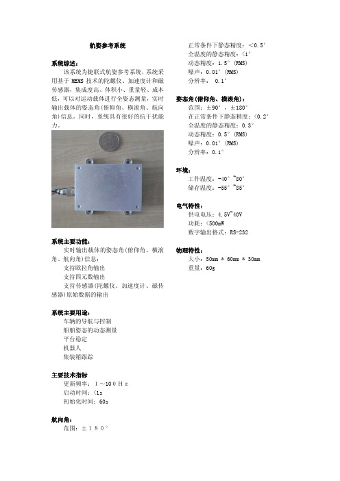
航姿参考系统
系统综述: 该系统为捷联式航姿参考系统,系统采用基于MEMS 技术的陀螺仪、加速度计和磁传感器,集成度高、体积小、重量轻、成本低,可以对运动载体进行全姿态测量,实时输出载体的姿态角(俯仰角、横滚角、航向角)信息。
同时,系统具有很好的抗干扰能
力。
系统主要功能: 实时输出载体的姿态角(俯仰角、横滚角、航向角)信息; 支持欧拉角输出 支持四元数输出
支持传感器(陀螺仪、加速度计、磁传感器)原始数据的输出
系统主要用途: 车辆的导航与控制 船舶姿态的动态测量 平台稳定 机器人 集装箱跟踪
主要技术指标
更新频率:1~100Hz 启动时间:<1s 初始化时间:60s
航向角:
范围:±180°
正常条件下静态精度:<0.5° 全温度的静态精度:<1° 动态精度:1.5°(RMS) 噪声:0.01°(RMS) 分辨率: 0.1°
姿态角(俯仰角、横滚角):
范围:±90°,±180°
在正常条件下静态精度:<0.2° 全温度的静态精度:0.3° 动态精度:0.5°(RMS) 噪声:0.01°(RMS) 分辨率:0.1° 环境:
工作温度:-40°~80° 储存温度:-55°~85°
电气特性:
供电电压:4.5V~40V 功耗:<500mW
数字输出格式:RS-232
物理特性:
大小:50mm * 60mm * 30mm 重量:60g。
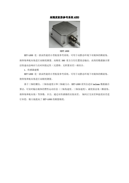
高精度航姿参考系统AHRS3DT-10003DT-1000是一款高性能的小型航姿参考系统,可用于动静态环境下对载体的横滚角、俯仰角和航向角进行高精度测量。
高精度360 度全方位位置姿态输出,高效的数据融合算法快速动态响应与长时间稳定性(无漂移,无积累误差)相结合。
1、传感器建模3DT-1000是一款高性能的小型航姿参考系统,可用于动静态环境下对载体的横滚角、俯仰角和航向角进行高精度测量。
基于三轴陀螺仪、三轴加速度计和三轴磁力计,3DT-1000采用自适应kalman数据融合算法,可实时输出载体的惯性运动信息(三轴角速度、三轴加速度)、最优姿态角(横滚角、俯仰角和航向角)等参数,并且,通过对传感器的安装误差、轴间正交误差和温度误差进行补偿,极大地提高了3DT-1000的测量精度。
2、传感器的数据融合算法基于对陀螺仪、加速度计和磁力计的性能分析,3DT-1000以积分角速度的姿态角作为状态量、以重力加速度和地球磁场获得姿态角作为观测量、以载体运动状态信息建立增益调整因子,设计了基于四元数的自适应kalman滤波数据融合算法,获得载体在各个状态(静态和动态)下的最优姿态角,从而实现姿态和航向信息的快速动态和长时间稳定性(无漂移、无累计误差)相结合的效果。
为了获得高精度的载体姿态角,3DT-1000在进行传感器数据融合算法之前,对三轴陀螺仪、三轴加速度计和三轴磁力计进行了标定以及温度漂移等误差补偿。
默认情况下,3DT-1000以50Hz的输出频率,连续输出传感器信息,波特率默认为115200。
提供的硬件接口为UART232。
3、软硬件设计自主AHRS系统3DT-1000 荷兰VTi4、传感器标定1)俯仰角和横滚角的误差都会影响航向角精度,所以必须进行磁场倾斜补偿;必须提高姿态角的精度,例如抗震性能;俯仰角误差造成的航向角误差2)载体和周围环境的磁场都会影响航向角精度,所以必须进行磁场软硬体补偿;在产品应用过程中,周围肯定或多或少存在磁场干扰,如铁块等硬体;在应对这些干扰的情况,我们采用了磁场倾斜补偿和软硬体补偿:提出全新磁场倾斜补偿模型,该模型考虑了俯仰角和横滚角对磁场影响,实现全方位的磁场补偿;提出全新磁场软硬体补偿算法,构建虚拟Z轴,两维磁场补偿达到三维磁场补偿效果,适合车载系统;5、姿态角性能首先我们以数据的形式给出产品3DT-1000的姿态角性能参数抗线性加速度抗线性加速度静态阶跃下面我们给出AHRS 的3DT-1000的卓越的详细性能参数:参数指标单位 姿态角测量范围:俯仰角/横滚角 90±/180±度 静态精度 0.4 度 动态精度 1.5[1](RMS)度 分辨率 0.1 度 重复度 0.2 度 输出速率 100(MAX )Hz 航向角 测量范围 180±度 静态精度 0.5[2] 度 动态精度 1.5[1](RMS)度 分辨率 0.1 度 重复度 0.2 度 输出速率 100(MAX )Hz5应用:机器人虚拟现实云台姿态稳定随钻姿态测量车辆姿态监控其他姿态航向测量领域。
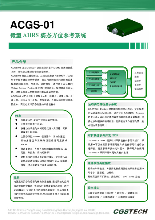
产品介绍产品介绍ACGS-01 是CGSTECH 公司提供的基于MEMS 技术的低成本的,高性能三维运动姿态测量系统。
ACGS-01包含三轴陀螺仪、三轴加速度计(即IMU ),三轴电子罗盘等辅助运动传感器,通过内嵌的低功耗处理器输出校准过的角速度,加速度,磁数据等,通过基于四元数的Motion Sensor Fusion 算法进行数据融合,实时输出以四元数、欧拉角等表示的零漂移三维运动姿态数据。
ACGS-01可广泛应用于航模无人机、机器人、摄像云台、天线云台、地面及水下设备、虚拟现实、人体运动分析等需要低成本、高动态三维姿态测量的产品设备中。
ACGS-01微型AHRS 姿态方位参考系统姿态方位参考系统硬件系统高度集成硬件系统高度集成紧凑的外观设计,方便开发集成到其他的系统和应用中尺寸小,重量轻,功耗低具有高度的可扩展性,提供串口,SPI ,CAN 总线运动姿态捕捉显示系统运动姿态捕捉显示系统CGSTECH Explore 提供图形化的显示界面,使开发者对运动姿态所见即所得,通过使用CGSTECH Explore 内置工具可以迅速完成内置传感器的各种设置校准,包括软铁和硬铁的磁场校准,让开发者工作化繁为简,集中精力于系统设计输出模式输出模式三维全姿态数据(四元数 / 欧拉角 / 旋转矩阵) 三维加速度 / 三维角速度 / 三维地磁场强度可扩展性软件开发 SDKCGSTECH SDK 提供针对不同设备的多层次接口,保证用户不仅在桌面系统还是嵌入式设备都可以进行快速开发,满足系统开发的定制要求,使得用户在使用CGSTECH 系列产品时更加具有自主性特点高精度360 度全方位空间姿态输出。
无需水平静态下启动。
快速动态响应与长时间稳定性(无漂移,无积累误差)相结合。
全固态微型MEMS 惯性器件,三轴加速度、三轴角速度和三轴磁场强度计高度集成9DOF 。
快速更新率,多种可编程的数据输出模式(四元数,欧拉角,旋转矩阵等)。
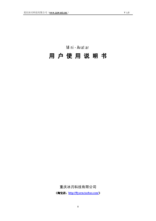
Mini-Avatar用户使用说明书重庆冰刃科技有限公司(淘宝店:/)1 概述Mini-Avatar(简化版)为一款微型航姿参考模块,提供9自由度的传感器信息(3轴加速度+3轴陀螺仪+3轴磁场计),该模块还实时的提供经卡曼滤波优化的静态和动态姿态信息。
模块3.3V供电,典型工作电流40mA,更适合要求低功耗的应用场合,比如采用电池供电的手持测试设备,飞行控制,玩具等。
模块整体大小24mm*24mm*3mm,输出孔采用传统的2.54mm间距设计,4个方向的加强型半孔工艺设计,可以更灵活的方便客户安装调试。
2 性能参数方向量程360 度, 任意轴传感器量程陀螺: +/-500 deg/s;加速度: +/- 2 G ; 磁场: +/-1.3 Gauss精度静态精度:横滚,俯仰0.1度,方位1度(无磁环境)动态精度:1度。
输出格式欧拉角(Pitch, Roll, Yaw);传感器独立数据;数字输出TTL串口带宽100 Hz;串口数据速率115200 Kb(如需其他波特率,请提前说明)供应电压DC 3.3V供应电流<40 mA操作温度-40 to +70 ℃尺寸24x 24 x 3 (mm x mm x mm)重量 2.5g* 只提供简单的标定,尤其是磁场环境客户可以根据说明自行标定* 固件版本有3种:陀螺仪量程500°/s ;陀螺仪量程2000°/s ;默认提供为:陀螺仪量程500°/s的9轴固件如有特殊需要,请提前联系。
3 接口说明PIN 名称功能描述1 GND 地2 GND 地3 NRST 系统复位4 VCC 3.3V供电5 WKUP Stm32唤醒功能6 TX2 Stm32串口27 RX2 Stm32串口28 GND 地9 GND 地10 NC 未用11 NC 未用12 GND 地13 NC 未用14 NC 未用15 NC 未用16 GND 地17 GND 地18 VCC 3.3V供电19 PA8 Stm32之PA820 TX1 Stm32串口121 RX1 Stm32串口122 PA11 Stm32之PA1123 PA12 Stm32之PA1224 VCC 3.3V供电25 GND 地26 RES 保留27 RES 保留28 RES 保留29 RES 保留30 RES 保留31 BOOT0 Stm32之Boot0(需接电阻下拉)32 VCC 3.3V供电注:STM32的IO功能未开放模块推荐应用电路:4 使用说明4.1 坐标系定义系统的坐标系定义如图1所示,X轴指向载体的前方,Y轴指向载体的右方,Z轴指向载体的下方。

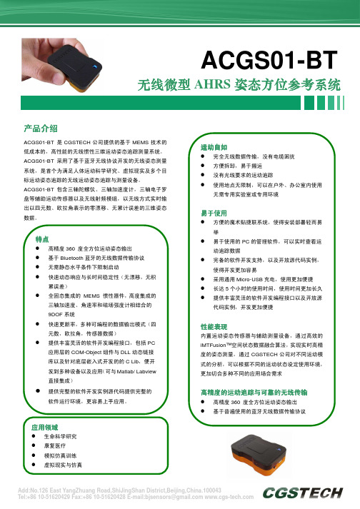
产品介绍产品介绍ACGS01-BT 是CGSTECH 公司提供的基于MEMS 技术的低成本的,高性能的无线惯性三维运动姿态追踪测量系统。
ACGS01-BT 采用了基于蓝牙无线协议开发的无线姿态测量系统,是首个为满足人体运动科学研究、虚拟现实及多个目标运动姿态追踪的无线运动姿态追踪与测量设备。
ACGS01-BT 包含三轴陀螺仪、三轴加速度计,三轴电子罗盘等辅助运动传感器以及无线射频模组,以无线方式实时输出以四元数、欧拉角表示的零漂移、无累计误差的三维姿态数据。
ACGS01-BT无线无线微型微型AHRS 姿态方位参考系统姿态方位参考系统 特点特点高精度360 度全方位运动姿态输出 基于Bluetooth 蓝牙的无线数据传输协议 无需静态水平条件下限制启动快速动态响应与长时间稳定性(无漂移,无积累误差)全固态集成的 MEMS 惯性器件,高度集成的三轴加速度、角速率和磁场强度计相结合的9DOF 系统 快速更新率,多种可编程的数据输出模式(四元数,欧拉角,传感器数据)提供丰富灵活的软件开发编程接口,包括PC 应用层的COM-Object 组件与DLL 动态链接库以及针对底层嵌入式开发的的C Lib ,便开发到多种设备以及应用(可与Matlab/ Labview 直接集成)提供完整的软件开发实例源代码提供完整的软件运行环境,更容易上手应用。
应用领域应用领域生命科学研究 康复医疗模拟仿真训练 虚拟现实与仿真ACGS01-BT 系统性能指标系统性能指标分立传感器性能分立传感器性能传感器性能转动角度 加速度磁场维度三轴 三轴 三轴满量程 (标准值) ± 2000 deg/s ± 50 m/s² ± 450 mGauss 线性度0.1% of FS 0.2% of FS 0.1% of FSBias stability (1σ) 1 deg/s 0.02 m/s² 0.1 mGauss Scale Factor stability (1σ) -0.03% 0.5%噪声(Noise ) 0.03 deg/s/√Hz 0.002 m/s²/√Hz 0.5 mGauss (1σ) Alignment error 0.1 deg 0.1 deg 0.1 degBandwidth 100 Hz 50 Hz 10 Hz (50Hzmax ) 最大更新率100 Hz100 Hz50 Hz姿态和航向动态范围 ± 360 deg - Pitch/ -Roll/ -Heading 加速度 ±5/160 m/s² (±5/16g) 角速度 ±2000°/sec 静态精度 俯仰/横滚 < 0.3 deg 静态精度 航向1< 0.5 deg 动态精度22 deg RMS 角度分辨率0.05 deg最大更新率 外部80 Hz内部100 Hz 1 无干扰磁场环境下测量 2 在CGSTECH 数据融合算法下测定,取决于运动类型 环境温度 -20.... +60 o C 典型环境 0.... +40 o C 尺寸 W59×L34×H14mm 重量 32 gACGS01-BT 无线微型AHRS 姿态方位参考系统 基于普遍使用的蓝牙无线数据传输协议采用惯性传感器与地磁传感器方式,完全自由度的运动追踪,无光线与使用环境的限制 无需安装辅助设施以及特殊使用环境 ISM2.4G 无线数据频率,全球通用 工作距离:10M 锂电池可充电方式充电LED 显示 低电压显示充电时间:1.5小时 工作续航时间:5小时无线数据更新率:数据更新率取决于所连接的无线运动追踪设备数量(特殊情况可增加数据收集主设备数量)虚拟现实与仿真 生命科学研究 康复医疗 体育竞技训练 人体运动分析测量 3D 虚拟互动体感交互感知3D 影视动作捕捉模拟仿真训练第三方开发支持第三方开发支持ACGS01-BT 无线微型AHRS 姿态方位参考系统。
Number:CTSO-C201Approved by:Xu ChaoqunChina Civil Aviation Technical Standard OrderAttitude and Heading Reference Systems (AHRS)1. Purpose.This China Civil Aviation Technical Standard Order (CTSO) is for manufacturers applying for Attitude and Heading Reference Systems (AHRS) CTSO authorization (CTSOA). This CTSO prescribes the minimum performance standards(MPS) that Attitude and Heading Reference Systems (AHRS) must first meet for approval and identification with the applicable CTSO marking.2. Applicability.This CTSO affects new application submitted after its effective date. Major design changes to article approved under this CTSO will require a new authorization in accordance with section 21.353 of CCAR-21-R4.3. RequirementsNew models of AHRS identified and manufactured on or after theeffective date of this CTSO must meet the MPS qualification and documentation requirements in sections 2.1, 2.2.1, and 2.2.2 of RTCA Document No. RTCA/DO-334, Minimum Operational Performance Standards (MOPS) for Solid-State Strap-Down Attitude and Heading Reference Systems (AHRS), dated March 21, 2012. If AHRS provides heading, turn and slip, degraded mode, uses aiding, includes a display, or provides information generated by the AHRS to a stand-alone display,then the applicant must also meet the requirements as listed in the table below.Optional Functions/Mode/Source FunctionalQualificationHeading 2.2.3Turn and Slip 2.2.5Degraded Mode 2.2.4Aiding 2.2.6Display 2.5a. Functionality. This CTSO’s standards apply to solid statestrap-down AHRS intended to output pitch and roll attitude that does notuse gimbaled sensors. It also addresses the optional functions of heading,turn, slip and the display of information provided by an AHRS.b. Failure Condition Classifications.There is no standard minimumfailure condition classification for this TSO. The failure condition classification appropriate for the equipment will depend on the intendeduse of the equipment in a specific aircraft. Document the loss of functionand malfunction failure condition classification for which the equipmentis designed.c. Functional Qualification. Demonstrate the required functional performance under the test conditions specified in RTCA/DO-334, Section 2.4. If the AHRS includes a display, demonstrate the required functional performance of the display under the test conditions specified in RTCA/DO-334, Section 2.6.d. Environmental Qualification. Demonstrate the required performance under the test conditions specified in RTCA/DO-334, Section 2.3, using standard environmental conditions and test procedures appropriate for airborne equipment. RTCA/DO-334 requires the use of RTCA/DO-160G; however, the applicant may use a different standard environmental condition and test procedure than RTCA/DO-160G, provided the standard is appropriate for AHRS.Note: The use of RTCA/DO-160D (with Changes 1 and 2 only, incorporated) or earlier versions is generally not considered appropriate and will require substantiation via the deviation process as discussed in paragraph 3.g of this CTSO.e. Software Qualification. If the article includes software, develop the software according to RTCA, Inc. document RTCA/DO-178B, Software Considerations in Airborne Systems and Equipment Certification, dated December 1, 1992 to at least the software level consistent with the failure condition classification defined in paragraph 3.b of this CTSO.Note: The certification liaison process objectives will be considered satisfied after CAAC review of the applicable life cycle data.f. Electronic Hardware Qualification. If the article includes complex custom airborne electronic hardware, develop the component according to RTCA/DO-254, dated April 19, 2000, Design Assurance Guidance for Airborne Electronic Hardware, to at least the design assurance level consistent with the failure condition classification defined in paragraph 3.b of this CTSO. For custom airborne electronic hardware determined to be simple, RTCA/DO-254, paragraph 1.6 applies.Note: The certification liaison process objectives will be considered satisfied after CAAC review of the applicable life cycle data.g. Deviations. For using alternative or equivalent means of compliance to the criteria in this CTSO, the applicant must show that the equipment maintains an equivalent level of safety. Apply for a deviation under the provision of 21.368(a) in CCAR-21-R4.4. Marking.a. Mark at least one major component permanently and legibly with all the information in 21.423(b) of CCAR-21-R4. The marking must include the serial number.b. Also, mark the following permanently and legibly, with at least the manufacturer’s name, subassembly part number, and the CTSOnumber:(1) Each component that is easily removable (without hand tools); and,(2) Each subassembly of the article that manufacturer determined may be interchangeable.c. If the article includes software and/or airborne electronic hardware, then the article part numbering scheme must identify the software and airborne electronic hardware configuration. The part numbering scheme can use separate, unique part numbers for software, hardware, and airborne electronic hardware.d. The applicant may use electronic part marking to identify software or airborne electronic hardware components by embedding the identification within the hardware component itself (using software) rather than marking it on the equipment nameplate. If electronic marking is used, it must be readily accessible without the use of special tools or equipment.5. Application Data Requirements.The applicant must furnish the responsible certification personnel with the related data to support design and production approval. The application data include a statement of conformance as specified in section 21.353(a)(1) in CCAR-21-R4 and one copy each of the followingtechnical data:a. A Manual(s) containing the following:(1) Operating instructions and equipment limitations sufficient to describe the equipment’s operational capability.(2) Describe in detail any deviations.(3) Installation procedures and limitations sufficient to ensure that the AHRS, when installed according to the installation or operational procedures, still meets this CTSO’s requirements. Limitations must identify any unique aspects of the installation. The limitations must include a note with the following statement:“This article meets the minimum performance and quality control standards required by a China civil aviation technical standard order (CTSO). Installation of this article requires separate approval.”(4) For each unique configuration of software and airborne electronic hardware, reference the following:(a) Software part number including revision and design assurance level;(b) Airborne electronic hardware part number including revision and design assurance level; and(c) Functional description.(5) A summary of the test conditions used for environmental qualifications for each component of the article. For example, a form asdescribed in RTCA/DO-160G, Environmental Conditions and Test Procedures for Airborne Equipment, Appendix A.(6) Schematic drawings, wiring diagrams, and any other documentation necessary for installation of the AHRS.(7) List of replaceable components, by part number, that makes up the AHRS. Include vendor part number cross-references, when applicable.b. Instructions covering periodic maintenance, calibration, and repair, for the continued airworthiness of AHRS. Include recommended inspection intervals and service life, as appropriate.c. If the article includes software: a plan for software aspects of certification (PSAC), software configuration index, and software accomplishment summary.d. If the article includes simple or complex custom airborne electronic hardware, a plan for hardware aspects of certification (PHAC), hardware verification plan, top-level drawing, and hardware accomplishment summary (or similar document, as applicable).e. A drawing depicting how the article will be marked with the information required by paragraph 4 of this CTSO.f. Identify functionality or performance contained in the article not evaluated under paragraph 3 of this CTSO (that is, non-CTSO functions). Non-CTSO functions are accepted in parallel with the CTSOauthorization. For those non-CTSO functions to be accepted, the applicant must declare these functions and include the following information with CTSO application:(1) Description of the non-CTSO function(s), such as performance specifications, failure condition classifications, software, hardware, and environmental qualification levels. Include a statement confirming that the non-CTSO function(s) don’t interfere with the article’s compliance with the requirements of paragraph 3.(2) Installation procedures and limitations sufficient to ensure that the non-CTSO function(s) meets the declared functions and performance specification(s) described in paragraph 5.f.(1).(3) Instructions for continued performance applicable to the non-CTSO function(s) described in paragraph 5.f.(1).(4) Interface requirements and applicable installation test procedures to ensure compliance with the performance data defined in paragraph 5.f.(1).(5) Test plans, analysis and results, as appropriate, to verify that performance of the hosting CTSO article is not affected by the non-CTSO function(s).(6) Test plans, analysis and results, as appropriate, to verify the function and performance of the non-CTSO function(s) as described in paragraph 5.f.(1).g. The quality system description required by section 21.358 of CCAR-21-R4, including functional test specifications. The quality system should ensure that it will detect any change to the approved design that could adversely affect compliance with the CTSO MPS, and reject the article accordingly.h. Material and process specifications list.i. List of all drawings and processes (including revision level) that define the article’s design.j. Manufacturer’s CTSO qualification report showing results of testing accomplished according to paragraph 3.c of this CTSO.k. Provide the AHRS modes of operation and attitude, heading, and turn and slip categories for equipment per RTCA/DO-334, section 1.7.1 in installation manual.6. Manufacturer Data Requirements.Besides the data given directly to the authorities, have the following technical data available for review by the authorities:a. Functional qualification specifications for qualifying each production article to ensure compliance with this CTSO.b. Article calibration procedures.c. Schematic drawings.d. Wiring diagrams.e. Material and process specifications.f. The results of the environmental qualification tests conducted according to paragraph 3.d of this CTSO.g. If the article includes software, the appropriate documentation defined in the version of RTCA/DO-178B specified by paragraph 3.e of this CTSO, including all data supporting the applicable objectives in Annex A, Process Objectives and Outputs by Software Level.h. If the article includes complex custom airborne electronic hardware, the appropriate hardware life cycle data in combination with design assurance level, as defined in RTCA/DO-254, Appendix A, Table A-l. For simple custom airborne electronic hardware, the following data: test cases or procedures, test results, test coverage analysis, tool assessment and qualification data, and configuration management records, including problem reports.i. If the article contains non-CTSO function(s), the applicant must also make available items 6.a through 6.h as they pertain to the non-CTSO function(s).7. Furnished Data Requirements.a. If furnishing one or more articles manufactured under this CTSO to one entity (such as an operator or repair station), provide one copy or technical data and information specified in paragraphs 5.a and 5.b of thisEnglish Translation Version for Reference Only CAAC CTSO-C201 CTSO. Add any data needed for the proper installation, certification, use, or for continued compliance with the CTSO, of the AHRS.b. If the article contains declared non-CTSO function(s), include one copy of the data in paragraphs 5.f.(1) through 5.f.(4).8. Availability of Referenced Documents.Order RTCA documents from:Radio Technical Commission for Aeronautics, Inc.1150 18th Street NW, Suite 910, Washington D.C. 20036You may also order them online from the RTCA Internet website at: .- 11 -。
卫星导航专业词语缩写中英文对照对照表检索(超链接)A B C D E F GH I J K L M NO P Q R S TU V W X Y Z中英文对照表A1 PPM - 1 Pulse Per Minute 分脉冲1 PPS - 1 Pulse Per Second 秒脉冲2D 二维定位3D 三维定位A/D - Analog to Digital 模拟/数字信号转换A/J - Anti-Jamming 反人为干扰ADF - Automatic Direction Finder 自动定向仪ADOP - Attitude Dilution of Precision 姿态精度因子AE - Antenna Electronics 天线电子学AFB - Air Force Base 美国空军基地AFI - Automatic Fault Indication 自动错误显示AFS - Air Force Station 空间站AHRS - Attitude and Heading Reference System 姿态方向参考系统AIMS - Airspace Traffic Control Radar Beacon System IFF Mark XII System 空中交通监控雷达信标系统敌我识别标志XII系统AOC - Auxiliary Output Chip 辅助输出芯片AOPA - Aircraft Owner & Pilot Association 飞机所有者及飞行员协会 AS - Anti-Spoofing 反电子欺骗ASIC - Application Specific Integrated Circuit 特殊应用集成电路ATC - Air Traffic Control 空中交通控制ATE - Automatic Test Equipment 自动测试仪器ATIS - Automatic Terminal Information Service 自动终端信息服务 ATRCC - Air Route Traffic Control Center 空中航线交通控制中心AMV - Auto Mag Var 自动磁偏角AVLN - Automatic Vehicle Location and Navigation 车辆自主定位和导航系统AWG- American Wire Gague 美国线规BCD - Binary Code Decimal二进制BIPM - International Bureau of Weights and Measures国际度量衡局BIT - Built-In-Test内置测试BNC同轴电缆接插件BPSK - Bi Phase Shift Keying双相移键控BRG - Bearing方位角(从当前位置到目的地的方向)C/A code - Coarse/Acquisition Code粗捕获码CAD - Computer Aided Design计算机辅助设计CADD - Computer Aided Design Device计算机辅助设计设备CDI - Course Deviation Indicator航线偏航指示CDMA - Code Division Multiplex Access码分多址CDU - Control Display Unit控制显示单元CEP - Circular Error Probable循环可能误差CMG - Course Mode Good从起点到当前位置的方位CMOS - Complementary Metal Oxide Semiconductor补充金属氧化物半导体COG - Course Over Ground对地运动方向CRPA - Controlled Radiation Pattern Antenna 受控辐射天线CTS - Course To Steer 到目的地的最佳行驶方向CTR - critical temperature resistor 临界温度电阻器CVR 飞行语音记录器CW - Continuous Wave 连续波DAC - Digital to Analog Converter 模拟/数字信号转换器DB - Decibel (X = 10 LogX dB) 分贝DGPS - Differential GPS 差分GPSDLM - Data Loader Module 数据装载模块DLR - Data Loader Receptable 数据装载接收器DLS - Data Loader System 数据装载系统DMA - Defense Mapping Agency 国防制图局DME - Distance Mesurement Equipment 测距设备DoD - Department of Defense 美国国防部DOP - Dilution of Precision 精度因子DRMS 二维均方根DRS - Dead Reckoning System 推测航行系统DSP - Digital Signal Processing 数字信号处理DT&E - Development Test and Evaluation 测试评估发展DTK - Desired Track 期望航向(从起点到终点的路线)ECEF - Earth Centered Earth Fixed 地固地心直角坐标系ECP - Engineering Change Proposal 工程更改建议EDM - Electronic Distance Measurement 电子测距EFIS - Electronic Flight Instrument System 电子飞行仪器系统EM - Electro Magnetic 电磁EMCON - Emission Control 发射控制EPE - Estimated Position Error 估计位置误差ESGN - Electrically Suspended Gyro Navigator 电子陀螺导航仪ETA - Estimated Time of Arrival 估计到达时间ETE - Estimated Time Enroute 估计在途时间(已当前速度计算)FAA - Federal Aviation Administration (美国)联邦航空局FCC - Federal Communication Commission (美国)联邦通信委员会FDAU - Flight Data Acquisition Unit 飞行数据采集系统FDR - Flight Data Recorder 飞行数据记录器FGCS - Federal Geodetic Control Subcommittee 美国联邦大地测量管制委员会FPL - Flight Plan 飞行计划FRPA - Fixed Radiation Pattern Antenna 固定发射天线FSS - Flying Spot Scanner 飞点扫描设备GaAs - Gallium Arsenide 镓砷化物GDOP - Geometric Dilution of Precision 几何精度衰减因子GLONASS 俄国全球定位系统GMDSS - Global Marine Defense Safe System 全球海上安全救助系统GMT - Greenwich Mean Time 格林威治时间GPS - Global Positioning System 全球定位系统HAI - Helicopter Association International 世界直升机协会HAMC - Harbin Aircraft Manufacturing Company 哈尔滨飞机制造厂HDOP - Horizontal Dilution of Precision 水平精度因子HQ USAF - Headquarters US Air Force 美国空军总部HIS - Horizontal Situation Indicator 水平位置指示HV - Host Vehicle 主机ICAO - International Civil Aviation Organization 国际民航组织ICD - Interface Control Document 界面控制文件ICS - Internal Communication System 内部通信联络系统IF - Intermediate Frequency 中频IFF - Identification Friend or Foe 敌我识别IFR – Infrared 红外的,红外线IFR - Instrument Flight Rules 仪表飞行规则I-Level - Intermediate Level 中间层ILS - Instrument Landing System 仪表着陆系统INMARSAT - INternational MARitime SATallite Organization 国际海事卫星组织INS - Inertial Navigation System 惯性导航系统I/O - Interface Option 界面接口选项Input/Output 输入/输出ION - Institute of Navigation 导航协会IOT&E - Initial Operational Test and Evaluation 原始操作测试和评估IP - Instrumentation Port 仪器使用端口ITS - Intermediate Level Test Set 中间层测试ITU - International Telecommunication Union 国际电信联合会J/S - Jamming to Signal Ration 信号干扰比JTIDS - Joint Tactical Information Distribution System 联合战术信息发布系统KHz – KiloHertz 千赫L1 GPS信号频率之一(1575.42 MHz)L2 GPS信号频率之一(1227.6 MHz)LAAS - Local Area Augmentation System 局域增强系统Lb 磅LCD - Liquid Crystal Display 液晶显示器LEP - Linear Error Probable 线性误差LO - Local Oscillator 本机振荡器LORAN - Long Range Radio Direction Finding System 罗兰导航系统LRIP - Low Rate Initial Production 小批量试生产LRU - Line Replaceable Unit 线性可替代单元M/S - Meters per Second 米/秒MCS - Master Control Station 主控站MCT: Mean Corrective Maintenance Time 平均矫正时间MHz – Megahertz 兆赫MaxCT - Maximum Corrective Maintenance Time 最大矫正时间MSA - Minimum Safe Altitude 最低安全高度MSL - Main Sea Level 公海平面Mean Sea Level 平均海拔MTBF - Mean Time Between Failure 平均无故障时间MTBM - Mean Time Between Maintenance 平均保持时间NASA - National Aeronautic Space Administration 美国国家航空航天局NAVSTAR - NAVigation Satellite Timing and Ranging 导航卫星测时测距NBAA - National Business Aviation Association 美国国家公务航空协会NDB - Non Direction Beason 无向信标NMEA - National Marine Electronics Association (美国)国家航海电子协会NMEA 0183: GPS接收机和其他航海电子产品的数据输出格式NOSC - Naval Ocean Systems Center 海军系统中心NRL - Naval Research Labratory 海军研究实验室NS - Nanosecond (10-9 second) 纳秒NSA - National Security Agency 国家安全局NTDS - Navy Tactical Data System 海军战术数据系统NTS - Navigation Technology Satellite 导航技术卫星OCS - Operational Control System 操作控制系统PCMCIA - Personal Computer Memory Card Internatuioal个人计算机存储卡国际协会AssociationPDOP - Position Dilution of Precision 位置精度衰减因子PPM - Parts Per Million (10-6) 百万分之一PPS - Precise Positioning Service 精密定位服务PRN - Pseudo Random Noise 伪随机噪声PVT - Position Velocity and Time 位置速度和时间RAIM - Receiver Autonomous Integrity Monitoring 接收机自动完好监视RAM - Reliability and Maintainability 可靠性和可维护性RCVR – Receiver 接收机RF - Radio Frequency 射频RMS - Root Mean Square 均方根RTCA - Radio Technical Commission for Aeronautics 航空无线电技术委员会RTCM - Radio Technical Commission for Maritime Services 航海无线电技术委员会,差分信号格式RTD - Realtime Differential 实时差分RTK - Realtime Kinematic 实时动态RX 接收SA - Selective Availability 选择可用性SAMSO - Space and Missile Systems Organization 空间导弹系统机构SEP - Spherical Error Probable 球概率误差SID - sudden ionospheric disturbance (通常由太阳引起的)电离层突然骚动SIL - System Integration Laboratory 系统集成实验室SPI - Special Position Identification 特殊位置标识SPS - Standard Positioning Service 标准定位服务SPSP - Spread Spectrum 扩频SSB - Single Sideband 单边带STDCDU:STanDard CDU 标准控制显示单元TACAN - Tactical Air Navigation 空战导航TAI - International Atomic Time 国际原子时间TCAS - Traffic Collision Avoidance System 交通避免碰撞系统TDOP - Time Dilution of Precision 时间精度衰减因子TRK – Track 航向TTFF - Time to First Fix 首次定位时间TTR - Target Tracking Radar 目标跟踪雷达TX 发射UE - User Equipment 用户设备UHF - Ultra High Frequency 超高频USNO - US Naval Observatory 美国海军天文台UTC - Universal Time Coordinated 世界协调时间VDOP - Vertical Dilution of Precision 高程精度衰减因子VFR - Visual Fligft Rules 目视飞行规则VHF - Very High Frequency 甚高频VHSIC - Very High Speed Integrated Circuit 超高速集成电路VLSIC - Very Large Scale Integrated Circuit 超大规模集成电路VMG - Velocity Made Good 沿计划航线上的航速VNAV - Vetical Navigation 高程导航VOR - Very High Frequency (VHF) Omnidirectional Range 甚高频全向信标VOX - Voice-operated transmission 音控传输WAAS - Wide Area Augmentation System 广域差分系统WGS-84 - World Geodetic System-1984 1984年世界大地坐标系,一种坐标格式WMS - Wide-area Master Station 广域主控站WRS - Wide-area Rover Station 广域流动站XTE - Crosstrack Error 偏航距YPG - Yuma Proving Ground 尤马实验场。
AHRS5600产品简介AHRS5600由三轴一体设计的中等精度光纤陀螺和石英挠性加速度计构成,可作为独立工作的惯性导航系统或捷联罗经。
产品特点结构紧凑的中精度光纤陀螺航姿系统;多种工作模式适用不同应用环境;应用领域大地测绘;车辆定位定向;船用罗经;轨道检测;无人机导航、控制;主要技术指标总体指标:重量:≤2kg;外形:100mm*100mm*96.5mm;供电:9-36V DC;稳态功耗:≤15W;工作温度:-40—+70℃;数据更新频率:200Hz(可定制最高1000Hz);接口:RS422\CAN\网络;连续工作时间:≥12小时;光纤陀螺仪指标:量程:±500°/s;零偏稳定性:≤0.05—0.2°/h(可定制);零偏重复性:≤0.05—0.2°/h(可定制);随机游走系数:≤0.02°/h0.5;标度因数重复性:≤100ppm;标度因数非线性:≤100ppm;带宽:≥500Hz;石英挠性加速度计(含数字采样电路)指标:量程:±10g;零偏稳定性:≤300ug(1秒平均);标度因数稳定性:≤100ppm(-40—+70℃,补后);纯惯性航姿模式指标:初始对准时间:≤5min;初始对准航向精度:0.3°—1°;罗经模式航向精度:0.3°secφ—1°secφ;开环航向保持精度:≤0.1°/h—0.3°/h;水平姿态精度:≤0.05°(RMS)AHRS6500光纤航姿系统产品介绍AHRS6500光纤航姿系统是一款全固态的高精度光纤陀螺航姿参考系统,能够在晃动环境下自主快速初始对准,为运动载体实时提供连续的航向、水平姿态和升沉等信息。
AHRS6500光纤航姿系统可选配内置卫星导航板卡,构成组合航姿系统,也可用于地面车辆、低动态飞行器的定位定向与姿态控制。
产品特点对准时间短;姿态精度高;动态精度高;长期工作性能稳定;应用领域船舶和水下潜器导航;海洋工程测量测绘;船用设备姿态基准;低速飞行器测姿;车辆定位定向;主要技术指标重量:≤3.5kg;外形:140mm*140mm*133mm(不含卫星导航板卡);150mm*140mm*133mm(内置卫星导航板卡);供电:9-36V DC;输出接口:RS422/CAN/以太网;数据更新率:≥200Hz;稳态功耗:≤15W;工作温度:-45—+70℃;工作纬度:南纬70°—北纬70°;启动时间:≤1min;初始对准时间:≤5min;航向精度:≤0.1°(惯性\卫星组合);≤0.06°/h(纯惯性状态);俯仰、横滚精度:≤0.05°(惯性\卫星组合);≤0.03°/h(纯惯性状态);角速率量程:±300°/s;线加速度量程:±10g;MTBF:≥3000h;振动环境:20-2000Hz,6.06g;F1060型光纤陀螺仪F1060型光纤陀螺仪具有启动时间短、体积小、重量轻、高带宽、低功耗、低成本、磁屏蔽性好等优势,在国内同型光纤陀螺仪中综合性能最优。
ahrs原理AHRS原理是指姿态和航向参考系统(Attitude and Heading Reference System)。
它是一种集成传感器和算法的系统,用于测量和跟踪飞行器、船舶、车辆等物体的姿态和航向信息。
AHRS主要由三轴加速度计、三轴陀螺仪和三轴磁力计组成。
AHRS的工作原理是通过三轴加速度计、陀螺仪和磁力计测量物体在空间中的加速度、角速度和磁场强度,并利用算法进行数据融合和姿态解算。
其中,加速度计测量物体的线性加速度,陀螺仪测量物体的角速度,磁力计测量物体所处的磁场强度。
在AHRS系统中,加速度计是用来测量物体的线性加速度的传感器。
它可以通过测量物体所受的惯性力来间接测量物体的加速度。
加速度计的工作原理是利用质量块的惯性来测量加速度。
当物体加速度发生变化时,质量块会受到相应的力作用,通过测量受力的变化可以计算出物体的加速度。
陀螺仪是用来测量物体的角速度的传感器。
它可以测量物体绕三个轴向的旋转速度。
陀螺仪的工作原理是利用物体的角动量守恒定律。
当物体发生旋转时,陀螺仪会受到相应的力作用,通过测量受力的变化可以计算出物体的角速度。
磁力计是用来测量物体所处的磁场强度的传感器。
它可以通过测量地球的磁场来确定物体的航向信息。
磁力计的工作原理是利用物体所受的磁场力来测量磁场强度。
当物体所处的磁场发生变化时,磁力计会受到相应的力作用,通过测量受力的变化可以计算出物体所处的磁场强度。
AHRS系统通过将加速度计、陀螺仪和磁力计的测量数据进行数据融合和姿态解算,可以实时地计算出物体的姿态和航向信息。
数据融合是指将多个传感器的测量数据进行融合,以提高系统的精度和鲁棒性。
姿态解算是指根据传感器的测量数据计算物体的姿态和航向信息。
常用的姿态解算算法有卡尔曼滤波算法和四元数算法。
AHRS系统广泛应用于航空、航天、航海、船舶、汽车、机器人等领域。
在飞行器中,AHRS系统可以用来测量和跟踪飞机、直升机、无人机等的姿态和航向信息,以实现飞行器的导航、自动控制和姿态稳定等功能。
3DM-GX4-25 是一个高性能的微型航姿参考系统(AHRS),使用最先进MEMS 传感技术。
它联合使用一个三向加速度计、一个三向陀螺仪、一个三向磁力计、一个温度传感器、一个气压高度计和一个运算复杂的卡尔曼滤波器的内嵌双核微处理器。
从而为用户提供精确的静态和动态姿态估计值和惯性测量。
这些技术使得3DM-GX4-25成为同级别产品中体积最小和重量最轻的设备。
优点
• 高性能陀螺仪
∙ 噪声密度: 0.005°/sec/√Hz ∙ 漂移: 10°/hr
∙ g 2 灵敏度: 0.003°/s/g 2 rms
• 专用的运算微处理器,提供精确的位置、速度和姿态估值数据
• 高速采样频率及多种数据输出方式 • -40 °C to +85 °C 工作环境温度 • 动态环境下高性能和高稳定性
• 市场上最小,最轻的带自适应卡尔曼滤波器的微型航姿参考系统(AHRS)
• SDK 软件开发包及开放通信协议,易于集成开发自主系统 应用
在动态环境下为用户提供非常稳定和精确的导航和姿
态数据 •无人机车导航
• 平台稳定性和人工地平线 • 天线和相机指向 • 机车健康及使用状态监测 • 侦察, 监视,目标截获 • 机器人控制 • 人员追踪
简介
3DM-GX4-25微型航姿参考系统提供各种输出数据参量,从完全标定的惯性测量(加速度,角速度和磁场或角度增量和速度向量增量)到计算的定向估值(欧拉角--俯仰、滚动、偏转;旋转矩阵和四元素。
由于使用了复杂的自适应卡尔曼滤波器,运算的估值数据不会受到磁场和直线运动的干扰。
偏移追踪和传感器噪声模式可以让用户对自己的设备应用进行微调,从而达到更好的测量效果。
所有参量都经过温度补偿和数学运算再转换到正交坐标系统。
系统的架构设计已经充分消除了多种可能的误差源:如由于温度变化引起的增益和补偿误差;由于电源电压波动引起的灵敏度变化等因素。
陀螺仪漂移非常小,基于复杂的运算估值技术,3DM-GX4-25性能已经接近满足战术应用级别的要求。
性能
精度±0.25°(roll & pitch) ±0.8°(heading)
重复性0.3°
分辨率<0.01°
测量范围360°(3轴)
加速度计量程标准:±5g (可选±16g)
陀螺仪量程标准:±300°/Sec
可选:±75°/sec, ±150°/sec, 300°/sec, ±900°/sec
特点自适应卡尔曼滤波器追踪校准陀螺仪和加速度计漂移
磁力计磁场追踪补偿
机车动态模式选择
自适应测量噪声(开/关)
用户定义的面向坐标转换
可选的内部或外部航向源
地球磁场模式
WGS84 重力场模式
估算滤波器更新率500 Hz
IMU数据更新率 1 Hz to 1000 Hz
常规
接口USB 2.0 或RS232
波特率9,600 to 921,600 (默认:115,200) 供电电压 3.2 to 36 volts DC
功耗100mA (120mA max) Vpri(3.2V-5.5V); 550mW(800mW max) Vaux(5.2V-36V)
接头micro-DB9
工作温度-40 °C to +85 °C
震动极限500 G
尺寸规格36.0 x 24.4 x 11.1 mm(不含安装孔座) 重量16.5 g
软件开发包(SDK) 完全开放的通信协议和样本代码
IMU滤波器4阶滤波器:
模拟带宽限制滤波器;数字sigma-delta宽带抗混叠滤波器;数字均值滤波(用户可调节)采样频率为4 KHz,转换到物理单位;圆锥和划船效应积分补偿(1 KHz运算速度)
数据输出加速度、角速度、磁场、角速度增量、速度向
量增量、GPS时间、滤波器状况、姿态估值(欧
拉角、旋转矩阵、四元素)、姿态不确定值、
失重线性加速度、角速度偏移补偿
传感器加速度计陀螺仪磁力计气压计
测量范围±5 g ±300°/sec ±2.5 Gauss
-1800
to10000
m
非线性±0.03 % fs ±0.03 % fs ±0.4 % fs —
稳定性±0.04 mg 10°/hr ——
初始偏移
误差
±0.002 g ±0.05°/sec ±0.003 Gauss —
稳定性比
例因子
±0.05 % ±0.05 % ±0.1 %
噪声密度100 μg/√Hz 0.005°/sec/√Hz 100μGauss/√Hz
0.15m
RMS
校正误差±0.05°±0.05°±0.05°
可调节带
宽
225 Hz max 250 Hz max ——
采样速率 4 kHz 4 kHz 50 Hz 10Hz
分辨率<0.1mg <0.008°/sec —<0.1m
误差补偿0.06% 0.05% ——
增益误差0.05% 0.05% ——
非线性比
例因子
0.02%
0.06% max
0.02%
0.06% max
±0.0015 Gauss —
振动噪声—0.072°/srms/g2rms ——
振动校
正,
—0.003°/s/g2rms ——。