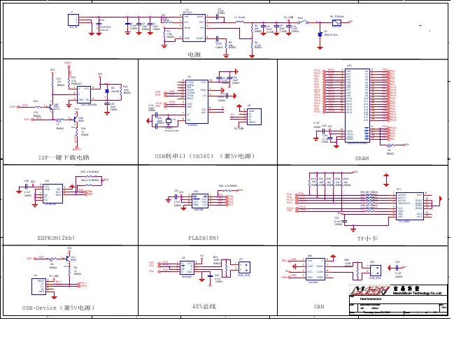
STM32开发板 SCH
- 格式:pdf
- 大小:2.62 MB
- 文档页数:6
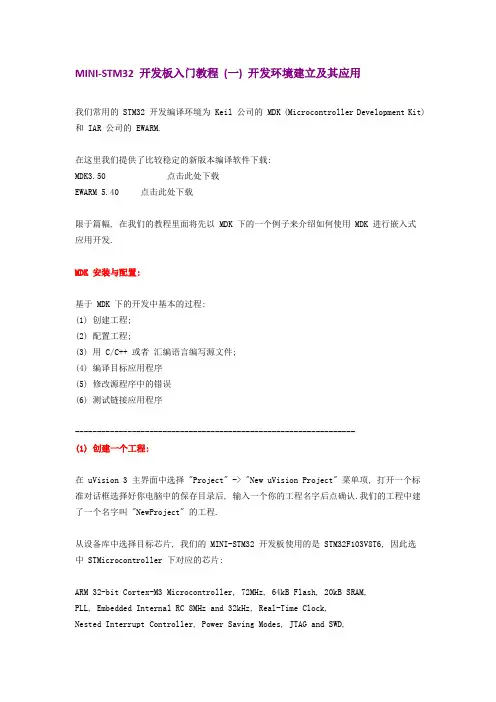
MINI-STM32 开发板入门教程(一) 开发环境建立及其应用我们常用的 STM32 开发编译环境为 Keil 公司的 MDK (Microcontroller Development Kit) 和 IAR 公司的 EWARM.在这里我们提供了比较稳定的新版本编译软件下载:MDK3.50 点击此处下载EWARM 5.40 点击此处下载限于篇幅, 在我们的教程里面将先以 MDK 下的一个例子来介绍如何使用 MDK 进行嵌入式应用开发.MDK 安装与配置:基于 MDK 下的开发中基本的过程:(1) 创建工程;(2) 配置工程;(3) 用 C/C++ 或者汇编语言编写源文件;(4) 编译目标应用程序(5) 修改源程序中的错误(6) 测试链接应用程序----------------------------------------------------------------(1) 创建一个工程:在 uVision 3 主界面中选择 "Project" -> "New uVision Project" 菜单项, 打开一个标准对话框选择好你电脑中的保存目录后, 输入一个你的工程名字后点确认.我们的工程中建了一个名字叫 "NewProject" 的工程.从设备库中选择目标芯片, 我们的 MINI-STM32 开发板使用的是 STM32F103V8T6, 因此选中 STMicrocontroller 下对应的芯片:ARM 32-bit Cortex-M3 Microcontroller, 72MHz, 64kB Flash, 20kB SRAM,PLL, Embedded Internal RC 8MHz and 32kHz, Real-Time Clock,Nested Interrupt Controller, Power Saving Modes, JTAG and SWD,3 Synch. 16-bit Timers with Input Capture, Output Compare and PWM,16-bit 6-ch Advanced Timer, 2 16-bit Watchdog Timers, SysTick Timer, 2 SPI, 2 I2C, 3 USART, USB 2.0 Full Speed Interface, CAN 2.0B Active, 2 12-bit 16-ch A/D Converter, Fast I/O Ports选择完芯片型号后会提示是否在目标工程中加入 CPU 的相关的启动代码, 如下图所示. 启动代码是用来初始化目标设备的配置, 完成运行的系统初始化工作, 因此我们选择 "是" , 这会使系统的启动代码编写工作量大大减少.----------------------------------------------------------------(2) 配置工程:选择菜单中 "Project" -> "Option for Target" 或者选择快捷菜单中的图标:因为 MINI-STM32 开发板上使用的就是 8M 的晶振且是使用的片内的 RAM 和 ROM 因此"taget" 下我们都可以使用默认的配置;在"Output"菜单下我们需要选中 "Creat Hex File" 来生成编译好的工程代码, 此工程可以通过仿真器或者串口 ISP 烧录进开发板中.注: ISP 烧录过程我们将在入门教程二中给大家介绍."Listing" "User" 菜单中我们保持默认即可."C/C++" 菜单为我们常用的菜单, 这里简单的介绍下他们的具体功能:PreProcesser Symbols 中的 Define, Undefine 菜单表示是工程的宏定义中的变量, 我们将在今后的教程中详细介绍这个功能.Optimization 为优化选项, Level0 为不优化, 这种模式最适合调试, 因为不会优化掉代码, 基本每个用到的变量都可以打断点. Level3 为优化等级最高, 最适合生产过程中下载到芯片中的代码.Include Path 为工程中的包含路径, 一般需将 .h 文件或者库文件的地址配置进去."Asm" 和 "Link" 将在今后的高级教程中介绍."Debug" 为我们调试使用的配置选项, "Use Simulator" 为使用软件仿真. 这里根据大家手里的仿真器来选择配置环境.如果你使用的是 Ulink, 那么就选择 "Ulink Cotex Debug", 如果你选择的是 JLINK, 那么就选择 " Cotex M3 Jlink", 如果你使用的是 ST 公司出的简易仿真器 ST-Link , 那么你就选择 "ST-Link Debug".注意: 右边当中的选项 "Run to main{}" 选项如果勾上就表示仿真时进入了就会进入到main 函数, 如果没有选上就会进入初始地址, 你需要自己打断点运行到你的主程序 main 处.当插上仿真器后选择上面右图中的 Setting 后会跳出一个仿真器的配置菜单. 左边会自动识别出你的仿真器的信息.如下图为 ULINK2 的信息:对于 SWJ 选项为三线制调试, 将在后面的高级教程中介绍.右下方有两个选项:"Verify Code Download" : 表示下载后校验数据"Download to flash": 表示当仿真的时候先将目标代码下载到 Flash 中.Trace 菜单为跟踪配置, 可以实时的将一些变量使用曲线的形式实时表示出来, 我们将在今后的高级教程中介绍这一项功能.注意: 市面上目前的盗版 Ulink2 不支持这项功能, 正版的支持, Jlink 也不支持这项功能."Flash Download" 菜单用来配置使用仿真器程序下载的配置选项, 大家务必选择好和你芯片配套的选项. 如果你是使用的别人模板下修改为你的工程, 这个选项请注意一下, 如果不正确将不能将你的代码下载到芯片中.配置好 "Debug" 后, 那么 "Utilities" 可以不用配置.如果你使用的是仿真器仿真, 在你已经正确得将目标板和仿真器建立了物理连接后, 请选择正确的仿真器进行配MINI-STM32 开发板入门教程 (二) ISP 在线下载程序ISP:in system programming简介:ISP: 用写入器将code烧入,不过,芯片可以在目标板上,不用取出来,在设计目标板的时候就将接口设计在上面,所以叫"在系统编程",即不用脱离系统;应用场合: 1,ISP 程序升级需要到现场解决,不过好一点的是不必拆机器了;ISP的实现一般需要很少的外部电路辅助实现,通常可利用单片机的串行口接到计算机的RS232口,通过专门设计的固件程序来编程内部存储器。
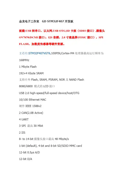
金龙电子工作室GD STM32F407开发板板载:USB转串口,以太网,USB OTG,SD卡座(SDIO接口),摄像头OV7670(DCMI接口),I2S音频,2.8寸液晶屏(FSMC接口),SPI FLASH,加数度传感器等硬件资源。
主芯片:STM32F407VGT6,100PIN,Cortex-M4处理器最高运行频率为168MHz1 Mbyte Flash192+4 Kbyte SRAM支持片外Flash, SRAM, PSRAM, NOR及NAND Flash8080/6800 模式的LCD接口USB 2.0 high-speed/full-speed device/host/OTG10/100 Ethernet MAC硬件IEEE 1588v22 CAN(2.0B Active)4 UART3 SPI 最高30 Mbit2 IIS8- to 14-bit摄像头接口最高48 Mbyte/s1-bit (default), 4-bit and 8-bit SD/SDIO MMC card12-bit 0.5μs A/D12-bit D/A17 timers 最高120MHz的计数频率I/O最高频率为60MHzISP及IAP编程407板载资料1.主芯片:STM32F407VGT6,100PIN2.以太网功能(PHY:DM9161AEP)3.2.8寸彩屏模块(FSMC总线方式),带加速度传感器4.摄像头OV7670(配套)5.JTAG 20PIN标准下载口6.MICRO SD卡接口(SDIO方式)B OTG主从设备接口B转串口(PL2303HX),可用USB下载程序,做串口实验9.RTC电池座10.I2S音频DA,支持WAV播放11.电源接口,开关(LED灯)12.四个用户按键,一个复位按键,四个用户LED13.所有IO在芯片四周引出,2.54MM标准间距产品包装:金龙407开发板<一块>OV7670摄像头模组 <一个>2.8寸彩屏模块 <一块>USB电源线<一条>DVD ROM光盘<一张>。
STM32开发板使用说明1、开发板使用到的软件及安装说明在开始学习开发板之前需要安装的软件有:1、KEIL3.80A,2、PL-2303HX驱动,3、串口调试助手,4、下载器MCUISP。
这些软件在课件文件下面的软件文件里。
具体安装步骤如下:1.KEIL3.80A的安装,打开路径:课件\软件\KEIL3.80A\MDK3.80A安装手册,根据上面的步骤安装软件。
2.PL-2303HX驱动的安装,打开路径:课件\软件\PL-2303HX新版驱动,可根据使用电脑的操作系统来选择安装的软件,如选择安装XP驱动,可打开XP驱动,根据里面的安装说明来安装软件。
一般只要运行PL-2303 Driver Installer。
exe就可以了。
3.串口调试助手的安装,打开路径:课件\软件\串口调试助手,点击sscom33。
exe即可,也可以创建快捷方式在桌面。
4.下载器MCUISP的安装,打开路径:课件\软件\下载器MCUISP,点击mcuisp。
exe 即可,也可以创建快捷方式在桌面。
2、开发环境介绍及使用说明首先是我们之前安装的keil3.80a。
再点击Project->New uVision Project如下图所示:弹出create new project 对话框,新建一个文件夹TEST,然后把工程名字设为test。
点击保存。
弹出选择器件的对话框,因为我们的开发板使用的是STM32F103RBT6 ,所以在这里我们选择STMicroelectronics 下面的STM32F103RB( 如果使用的是其他系列的芯片,选择相应的型号就可以了)。
如下图所示:点击OK,MDK会弹出一个对话框,问你是否加载启动代码到当前工程下面,这里我们选择是。
启动代码是一段和硬件相关的汇编代码。
是必不可少的!在上面点击了是以后,MDK 就把启动代码STM32F10x。
s 加入到了我们的工程下面。
如下图所示:到这里,我们就可以开始编写自己的代码了。
Open429Z-D User ManualContents1. Hardware introduction (2)1.1. What’s on board (2)2. Demo (4)2.1. ADC+DMA (4)2.2. CAN1 TO CAN2-Normal (5)2.3. DAC (5)2.4. DS18B20 (6)2.5. OV2640 (6)2.6. GPIO_Key (7)2.7. I2C (7)2.8. I2S_UDA1380 (8)2.9. NandFlash_SCB0 (8)2.10. SAI (9)2.11. SD_FatFS (9)2.12. SDIO (9)2.13. SPI (10)2.14. USART (11)3. Version update records (11)1. Hardware introduction 1.1. What’s on board[ Core interface ]1. STM32F429I-DISCO socketfor easily connecting the STM32F429I-DISCO 2. MCU pins connectorall the MCU I/O ports are accessible onexpansion connectors for further expansion 3. USB connectorUSB to UART via PL2303 USB TO UART board onboard MCU4. I2C1 / I2C2interface[ Other interfaces ]16. 5V DC jack17. 5V/3.3 V power input/outputusually used as power output, alsocommon-grounding with other user board 18. JTAG/SWD interfacefor debugging/programming[ Jumper ]easily connects to I2C peripherals such as I/O expander (PCF8574), FRAM (FM24CLXX), etc. 5. I2S2 / I2S3 / I2C1 interfacefor connecting I2S peripherals, such as Audio module.6. DCMI interfacefor connecting camera module 7. SDIO interfacefor connecting Micro SD module, features much faster access speed rather than SPI 8. CAN1 interfacecommunicates with accessory boards which feature the CAN device conveniently 9. CAN2 interfacecommunicates with accessory boards which feature the CAN device conveniently 10. UART3 interfaceeasily connects to RS232, RS485, USB TO 232, etc11. SPI1/SPI4 + AD/DA interfaceeasily connects to SPI peripherals such as DataFlash (AT45DBxx), SD card, MP3 module, etc MP3SPI1 features AD/DA alternative function, supports connecting AD/DA module as well 12. UART2 interfaceeasily connects to RS232, RS485, USB TO 232, etc13. 8-bit FSMC interfaceeasily connects to peripherals such as NandFlash, Ethernet, etc 14. SAI1 interfacefor connecting Audio peripherals, such as UDA1380 etc15. One-WIRE interfaceeasily connects to ONE-WIRE devices (TO-92 package), such as temperature sensor (DS18B20), electronic registration number (DS2401), etc.16. Joystick jumpershort the jumper to connect the joystick to default I/Os used in example code;open the jumper to connect the joystick to custom I/Os via jumper wires. 17. BOOT mode switchfor configuring BOOT0 pin 18. USB TO UART jumper[ Components ] 16. AMS1117-3.33.3V voltage regulator 17. PL2303USB to UART MCU 18. 5V DC jack 19. Power LED20. UART1 indicator LED 21. Joystickfive positions2. DemoKEIL MDK Version :4.7Programmer/Debugger: STM32F429I-DISCO onboard ST-LINK V2 Programming/Debugging interface: SWDConnect PC to the onboard USB TO UART connector via USB wireSerial port settings:2.1. ADC+DMA◆ OverviewAD acquisition demo◆ Hardware connectionConnect Analog Test Boardto SPI1(ADC+DAC )connector◆ Operation and resultRotate the onboard potentiometer, the below message will be printed on the serial debugging assistant:Select a proper COM port Baud rate115200Data bits 8Stop bits 1 Parity bits None Flow controlNone2.2. CAN1 TO CAN2-Normal◆ OverviewCAN demo◆ Hardware connection◆ Hardware connectionConnect the two CAN modules to theonboard CAN interfaces◆ Operation and resultYou may see the below result on the serial debugging assistant:2.3. DAC◆ OverviewDAC demo◆ Hardware connectionConnect the Analog Test Board to the SPI1(ADC+DAC )connectorConnect the Analog Test Board onboard 5Vinterface to the board onboard 5V interface viajumper wire.◆ Operation and resultYou may hear sound from the Analog Test Board2.4. DS18B20◆ OverviewDS18B20 demo◆ Hardware connectionConnect the DS18B20 module to the one-wire connector ◆ Operation and resultThe below information will be printed on the serial debugging assistant2.5. OV2640◆ OverviewCamera OV2640 demo ◆ Hardware connectionConnect the OV2640 Camera Board tothe onboard DCMMI connectorLaunch the serial debugging assistant, configuring the data as below: COM: COM3Baud rate: 115200 Data bits: 8 Parity bits: NO Stop bits: 1◆ Operation and result:Press “user” key, the captured image displayed on the serial debugging assistant:2.6. GPIO_Key◆ Overviewjoystick demo◆ Hardware connectionShort the JOYSTICK JMP on board ◆ Operation and resultPress the joystick, message will be printed on the serial debugging assistant accordingly.2.7. I2C◆ OverviewI2C EEPROM demo ◆ Hardware connectionConnect the AT24/FM24 Board to the board viaI2C connector (I2C1 or I2C2, depending on the software configuration).◆ Software configurationThe module connect to I2C1 connectorThe module connect to I2C2 connector #define Open_I2C1 //#define Open_I2C2//#define Open_I2C1 #define Open_I2C2◆ Operation and resultThe below information will be printed on the serial debugging assistant:2.8. I2S_UDA1380◆ OverviewI2S_UDA1380 demo ◆ Hardware connectionConnect the UDA1380 Board to the board via I2Sconnector.Connect the earphone to the UDA1380 Board viaLINEOUT connector◆ Operation and resultYou should hear music when press the RESET key2.9. NandFlash_SCB0◆ OverviewNandFlash demo ◆ Hardware connectionConnect the NandFlash Board to theboard via I2C2 connector.◆ Operation and resultThe below information will be printed on the serial debugging assistant:2.10. SAI◆ OverviewSAI demo◆ Hardware connectionConnect UDA1380 Board to the board via SAI1connector.Connect the earphone to the UDA1380 Board viaLINEOUT connector.◆ Operation and resultYou should hear music when press the RESET key.2.11. SD_FatFS◆ OverviewSD_FatFS demo ◆ Hardware connectionConnect the Micro SD Storage Board to theboard via SDIO connector.Insert the SD card to the Micro SD Storage Board socket.◆ Operation and resultMessage will be printed on the serial debugging assistant.2.12. SDIO◆ OverviewSDIO demo◆Hardware connectionConnect the Micro SD Storage Board to theboard via SDIO connector.Insert the SD card to the Micro SD Storage Board socket.◆ Operation and resultMessage will be printed on the serial debugging assistant.2.13. SPI◆ OverviewSPI demo◆ Hardware connectionConnect the AT45DBXX DataFlash Board via SPIconnector. (SPI1 or SPI4, depending on the software configuration◆ Software connectionModule connect to SPI1 connectorModule connect toSPI4 connector #define Open_SPI1 //#define Open_SPI4//#define Open_SPI1 #define Open_SPI4◆ Operation and resultInfo/messages printed on the serial debugging assistant:11 2.14. USART◆ OverviewUSART demo◆ Hardware connection◆ Operation and resultInfo/messages printed on the serial debugging assistant:3. Version update records VersionModification Date Author V1.0Initial Release 2014/05/17 Waveshare team。
兼容STM3210E-EV AL开发板采用STM32F103ZET6微控制器,带USB2.0,CAN2.0A/B,I2S,I2C,USART,SPI,DAC,FSMC,SDIO,64KB SRAM,512KB Flash,JTAG和SWD仿真下载接口。
软件代码和硬件电路兼容官方STM3210E-EV AL开发板,支持UCOS,uCLinux操作系统。
一、百为STM32开发板概述:1、硬件特性:l 两种供电方式,外部5V供电和USB供电方式l 三种启动模式,下载模式、用户程序模式、内部SRAM启动模式l AK4642 I2S音频DAC,立体声耳机l MicroSD卡接口l 8Mbit SPI FLASH,1MB SRAM,128Mbit NOR Flash,64MB NAND Flashl I2C接口温度传感器芯片LM75Al 两个串口,其中一个带RTS/CTS控制l USB2.0 device接口l CAN2.0A/B兼容接口l JTAG仿真调试下载接口l 240x320 TFT彩屏l 五向游戏杆控制l 复位按键l 4个LED指示灯l RTC电池备份l 全部IO通过双排插针引出l BNC接口2、软件特性:l 简单不带库例程l 官方带库例程l 支持ST官方DEMO程序l 支持UCOS2.86+UCGUI3.90+ILI9320+TSC2046触摸l 支持FATFS+SDIO+helix软解码MP3l uCLinux操作系统l ST GUI库二、开发板硬件框图:硬件模块图:实物功能对照图:CONNETORSTM32F103ZET6SPI FLASHBOOT SELECTAK4642TF CARDAUDIO JACKADC INPUT开发板提供外部5V供电及USB供电两种方式,可通过JP13跳帽选择任意一种。
l 外部5V供电方式,JP13跳帽接PSUl USB供电方式,JP13跳帽接USB,默认USB供电方式l JP1连接1、2,VBAT接到备份电池l JP1连接2、3,VBAT接到3.3V2、启动方式l 从用户FLASH启动l 从系统存储器启动l 从内部SRAM启动开发板上有两种时钟源l X2,32KHz晶振作为RTC时钟源l X1,8MHz晶振作为MCU的时钟源,当使用内部RC震荡器作为时钟源时,可以将8MHz 晶振去掉4、复位方式STM32复位为低电平有效,开发板上有三种复位方式:l 上电复位l 通过开发板上的RESET按键复位l JTAG调试器输入复位信号5、音频AK4642音频芯片连接到STM32F103ZET6的I2S2接口,支持立体声耳机接口输出。
OLIMEXINO-STM32 development boardUser's manualAll boards produced by Olimex are ROHS compliantDocument revision E, November 2014Designed by OLIMEX Ltd, 2012SCHEMATIC:OLIMEXINO-STM32, board revision E https://LED2_E D23_ECAN_TPin #Signal Name Pin #Signal Name 1D23_EXT2D24(CANTX) 3D25(MMC_CS)4D265D276D287D29(SCL2)8D30(SDA2)9D31(#SS2)10D32(SCK2)DISCLAIMER© 2014 Olimex Ltd. Olimex®, logo and combinations thereof, are registered trademarks of Olimex Ltd. Other product names may be trademarks of others and the rights belong to their respective owners.The information in this document is provided in connection with Olimex products. No license, express or implied or otherwise, to any intellectual property right is granted by this document or in connection with the sale of Olimex products.The Hardware project is released under the Creative Commons Attribution-Share Alike 3.0 United States License. You may reproduce it for both your own personal use, and for commercial use. You will have to provide a link to the original creator of the project https:// on any documentation or website.You may also modify the files, but you must then release them as well under the same terms. Credit can be attributed through a link to the creator website: https://The software is released under GPL.It is possible that the pictures in this manual differ from the latest revision of the board.The product described in this document is subject to continuous development and improvements.All particulars of the product and its use contained in this document are given by OLIMEX in good faith. However all warranties implied or expressed including but not limited to implied warranties of merchantability or fitness for purpose are excluded. This document is intended only to assist the reader in the use of the product. OLIMEX Ltd. shall not be liable for any loss or damage arising from the use of any information in this document or any error or omission in such information or any incorrect use of the product.This evaluation board/kit is intended for use for engineering development, demonstration, or evaluation purposes only and is not considered by OLIMEX to be a finished end-product fit for general consumer use. Persons handling the product must have electronics training and observe good engineering practice standards. As such, the goods being provided are not intended to be complete in terms of required design-, marketing-,and/or manufacturing-related protective considerations,including product safety and environmental measures typically found in end products that incorporate such semiconductor components or circuit boards.Olimex currently deals with a variety of customers for products, and therefore our arrangement with the user is not exclusive. Olimex assumes no liability for applications assistance, customer product design, software performance, or infringement of patents or services described herein.THERE IS NO WARRANTY FOR THE DESIGN MATERIALS AND THE COMPONENTS USED TO CREATE OLIMEXINO-STM32. THEY ARE CONSIDERED SUITABLE ONLY FOR OLIMEXINO-STM32.For product support, hardware information and error reports mail to: ******************. Note that we are primarily a hardware company and our software support is limited.Please consider reading the paragraph below about the warranty of Olimex products.。
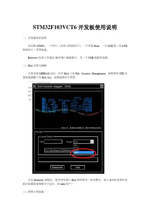
STM32F103VCT6开发板使用说明一:开发板简单说明由内核STM32,一个串口(及串口控制芯片),一个外接flash,一个LCD屏(及LCD 控制芯片)等等构成。
Relaview仿真工具通过20针接口链接板子,另一个USB线提供电源。
二:Keil安装与破解正常安装MDK410过后,打开Keil工具File->License Management,获取软件CID后复制进破解工具Keil_Lic,如图选择芯片类型点击Generate按钮后,将序列号填入Keil软件即可(如有警告,则上述动作需要在有执行权限的系统账号下运行,如adm用户)三:样例工程创建1:需要事前说明,实际工程文件的组织结构与Keil软件界面显示的是两回事情,电脑文件系统中的结构是文件实际存储的结构,是文件真实存在的地方,而Keil软件界面看见的只是一个工程结构,只是一个组,为了方便,这些组可以取和文件系统下的文件夹一样的名字,但实际上两者是互不影响,互不关联的,组,仅仅只是一个名字,创建了组,并不会创建出对应的文件夹来。
2:STM32工程一般划分为如下几个文件夹,(1)USER,存放用户自己的具体功能程序文件;(2)CORE,存放arm内核文件,启动文件等;(3)OBJ,存放编辑过程中产生的文件;(4)SYSTEM,存放arm自己的系统文件,分两个类型,一个是寄存器版本,代码精简,但什么都要自己去控制,另一个是库函数版本,被厂家封装好,便于调用,但代码量比较臃肿;(5)HARDW ARE,存放一些基本的硬件控制文件,如IIC,LCD,LED,FLASH,按键,触摸屏等;(6)FWLib,存放了芯片上所有外设的驱动文件。
3:以一个两灯交替闪亮的程序为例,需要在对应工作文件空间建立如下几个文件夹:USER,CORE,OBJ,SYSTEM,HARDW ARE(LED)。
4:打开Keil工具,选择Project->New μVersion Project,开始创建工程如图后紧接着需要选择关联的芯片类型,我们选择STMicroelectronics->STM32F103VC,可以看见芯片的相关硬件参数,点击Ok后会提示是否需要拷贝STM 32的启动代码到工程文件中,可以选择是,为了初学,可以选择否后手工添加。
Open32F0-D User ManualContents1. Overview (2)1.1. What’s on board (2)2. Demo (4)2.1. 8IOs (4)2.2. 24L01 (5)2.3. ADC+DMA (5)2.4. DAC+DMA (6)2.5. FATFS V0.08A-SD Card (6)2.6. GPIO LED (7)2.7. GPIO LED JOYSTICK (7)2.8. I2C (7)2.9. I2S UDA1380 & SD_FatFS(DMA) (8)2.10. JOYSTICK (8)2.11. LCD22-picture (8)2.12. LCD22_TouchPanel (9)2.13. One-Wire (10)2.14. SPI (10)2.15. uCOS-II-V2.91 (11)2.16. uCOS-II-V2.91+LCD (11)2.17. USART (11)3. Revision history (12)1. Overview 1.1. What’s on board[ Core interface ]1. STM32F0DISCOVERY socketfor easily connecting theSTM32F0DISCOVERY2. 8I/Os + DAC + ADC interfacefor connecting accessory boards such buttons, motors, AD/DA module etc.3. USART2 interfaceeasily connects to RS232, RS485, USB TO232, etc.4. SPI1/SPI2 interface[ Other interface ]10. 5V/3.3V power input/outputusually used as power output, alsocommon-grounding with other user board11. 5V DC jack12. MCU pins connectorall the MCU I/O ports are accessible onexpansion connectors for further expansion 13. SWD interfacefor debugging/programmingeasily connects to SPI peripherals such asDataFlash (AT45DBxx), SD card, MP3 module, etc.5. LCD connectorfor connecting touch screen LCD 6.USART1 interfaceeasily connects to RS232, RS485, USB TO 232, etc.7.I2C1 / I2C2 interfaceeasily connects to I2C peripherals such as I/O expander (PCF8574), FRAM (FM24CLxx), etc. 8.I2S / I2C1 interfaceeasily connects to I2S peripherals such as audio module, etc. 9.1-WIRE interfaceeasily connects to ONE-WIRE devices (TO-92 package), such as temperature sensor (DS18B20), electronic registration number (DS2401), etc.[ Jumper/switch ] •Joystick jumpershort the jumper to connect the joystick to default I/Os used in example code;open the jumper to connect the joystick to custom I/Os via jumper wires14. Boot mode switchfor configuring BOOT0 pin.[ Component ] 15. Power switch 16. Power indicator17. Joystick: five positions2. DemoKEIL MDK Version :4.54Programmer/Debugger: STM32F0DISCOVERY onboard SWD Programming/Debugging interface: SWDSerial port settings:2.1. 8IOs◆ Overview8bit I/Os demo◆ Hardware connectionConnect the RS232 board to the onboardUSART1 interfaceConnect the 8 Push Button to the onboard 8I/Os connector (Make sure the G pinheader is connect to the board GND pinheader)◆ Operation and result◆The below information will be printed on the serial debugging assistantSelect a proper COM portBaud rate 115200Data bits 8Stop bits 1 Parity bitsNoneFlow control None2.2. 24L01◆ OverviewNRF24L01 demo ◆ Hardware connectionConnect the RS232 board to the onboardUSART1 interfaceConnect the two NRF24L01 to the board viaSPI interface ◆ Software configurationTwo NRF24L01 are needed for this demo, configuring as below:When configuring as sending mode, enable: #define T_O_R 1, comment out: //#define T_O_R 0 When configuring as receiving mode, enable: #define T_O_R 0, comment out: //#define T_O_R 0. ◆ Operation and resultMessage will be printed on the serial debugging assistant.2.3. ADC+DMA◆ OverviewADC+DMA demo◆ Hardware connectionConnect the RS232 board to the onboardUSART1 interfaceConnect the Analog Test Board to the board via8 I/Os (ADC+DAC)◆ Operation and resultRotate the onboard potentiometer, the AD message will be printed on the serial debugging assistant:2.4. DAC+DMA◆ OverviewDAC+DMA demo◆ Hardware connectionConnect the Analog Test Board to the board via8 I/Os (ADC+DAC)Connect the 5V pinheaders on both the mainboard and the Analog Test Board via jumper wire◆ Operation and resultYou may hear sound from the Analog Test Board when press the Reset button2.5. FATFS V0.08A-SD Card◆ OverviewSD_FatFS demo ◆ Hardware connectionConnect the RS232 board to the onboardUSART1 interfaceConnect the Micro SD Storage Board to theboard via SDIO interface.Insert the SD card to the Micro SD Storage Board socketConnect the CD pin on the Micro SD StorageBoard to the board PB0 pin via Dupont wire.`◆ Operation and resultThe below information will be printed on the serial debugging assistant:2.6. GPIO LED◆ OverviewLED demo◆ Hardware connection ◆ Operation and resultThe two LEDs on the Discovery board blinking2.7. GPIO LED JOYSTICK◆ OverviewUser key demo◆ Hardware connection ◆ Operation and resultPress the User key, the LED status will change accordingly.2.8. I2C◆ OverviewI2C EEPROM demo ◆ Hardware connectionConnect the RS232 board to the onboardUSART1 interfaceConnect the AT24/FM24 Board to theI2CX connector ( connect to I2C1 or I2C2 depends on the program)◆ Operation and resultThe below information will be printed on the serial debugging assistant:2.9. I2S UDA1380 & SD_FatFS(DMA)◆ OverviewAudio file placed on SD Card (with FATFS) ◆ Hardware connectionConnect Micro SD Storage Board to the board viaSPI2 interface.Insert the SD card to the Micro SD Storage Boardsocket. Connect the CD pin of the Micro SD Storage Boardto the board PB0 pin via DuPont wire. Put “audio.wav“ file to the SD cardConnect UDA1380 Board to the board via I2Sconnector.Connect the earphone to the UDA1380 Board viaLINEOUT interface.◆ Operation and resultYou can hear music while pressing the RESET key.2.10. JOYSTICK◆ OverviewJOYSTICK demo ◆ Hardware connectionShort the JOYSTICK JMP ◆ Operation and resultThe LED status will change accordingly while press the JOYSTICK .2.11. LCD22-picture◆ OverviewLCD demoThis LCD is 2.2 inch resistive touch screen LCD, the resolution is 320x240, drive by mode of SPI, greatlyreduce the pins, MCU with little IO can also available to drive it.This demo shows dot, the drawing line, the drawing circle, character, etc displayed on the LCD. ◆ Hardware connectionConnect with 5V power via the 5VDC interface Connect ULINK2 to the board via SWD interfaceConnect the 2.2inch 320x240 Touch LCD (A) to theboard via LCD22 interface.◆ Operation and resultMessage will be displayed on the LCD.2.12. LCD22_TouchPanel◆ OverviewLCD demo1. Calibrate the touch screen by click three times, and then enter into drawing board in the touch screeninterface.2. You can draw lines freely on the drawing board. ◆ Hardware connectionConnect the 2.2inch 320x240 Touch LCD (A) to the board. ◆ Operation and resultMessage will be displayed on the LCDTouch-screen calibration interface◆ ApplicationHandheld device display2.13. One-Wire◆ OverviewOne-Wire demo◆ Hardware connectionConnect the RS232 board to the onboard USART1 interface Connect the DS18B20 to the board via One-Wire interface◆ Operation and resultThe below information will be printed on the serial debugging assistant:2.14. SPI◆ OverviewSPI demo◆ Hardware connectionConnect the AT45DBXX DataFlash Board to theboard via SPIX (to SPI1 or SPI2 depends on the program)Connect the RS232 board to the onboard USART1interface◆ Software configurationThe serial debugging assistant configuring:Launch the serial debugging assistant SSCOM32, choose related COM port, set baud rate as 115200, click to open it.◆ Operation and resultThe below information will be printed on the serial debugging assistant:2.15. uCOS-II-V2.91◆OverviewuCOSII demo◆Hardware connection◆Operation and resultThe two LED blinking.2.16. uCOS-II-V2.91+LCD◆OverviewuCOS-II-V2.91I demo◆Hardware connectionConnect the 2.2inch 320x240 Touch LCD (A) to the board◆Operation and resultMessage displayed on the LCD; LED blinking.2.17. USART◆OverviewUSART demo◆Hardware connection◆Operation and resultThe below information will be printed on the serial debugging assistant:3. Revision historyVersion Description Date AuthorV1.0 Initial revision 2014/05/17 Waveshare team。
stm32开发板课程设计一、课程目标知识目标:1. 理解STM32开发板的基本结构、性能参数及工作原理;2. 掌握STM32的编程环境搭建,包括Keil、STM32CubeMX等工具的使用;3. 学习并掌握C语言在STM32开发中的应用,如GPIO、中断、定时器等基本功能的使用;4. 了解嵌入式系统设计的基本流程,能够阅读并理解STM32相关技术文档。
技能目标:1. 能够独立搭建STM32开发环境,进行程序编写、编译、下载及调试;2. 运用所学的知识,设计并实现简单的嵌入式项目,如LED灯控制、温度传感器数据采集等;3. 学会分析并解决STM32编程过程中遇到的问题,提高实际操作能力。
情感态度价值观目标:1. 培养学生对嵌入式系统开发的兴趣,激发学习热情,提高自主学习能力;2. 培养学生团队合作意识,学会在团队中发挥个人优势,共同解决问题;3. 强化学生的实践操作能力,培养动手能力,使学生在实践中感受科技的魅力,增强创新意识。
分析课程性质、学生特点和教学要求,本课程旨在通过理论与实践相结合的方式,使学生在掌握STM32开发板基本知识的基础上,提高嵌入式系统设计能力,培养创新精神和实践能力。
课程目标分解为具体学习成果,便于后续教学设计和评估。
二、教学内容1. STM32开发板基础知识:介绍STM32的硬件结构、性能特点,使学生了解开发板的基本组成和功能;- 教材章节:第一章 嵌入式系统概述,第三节 STM32微控制器简介2. 开发环境搭建:讲解如何安装Keil、STM32CubeMX等编程工具,并指导学生进行实际操作;- 教材章节:第二章 嵌入式系统开发环境,第一节 开发工具的安装与配置3. C语言编程基础:回顾C语言基础知识,重点讲解在STM32中的应用;- 教材章节:第三章 C语言编程基础,第二节 C语言在嵌入式系统中的应用4. STM32基本功能编程:学习GPIO、中断、定时器等模块的使用,并通过实例进行讲解;- 教材章节:第四章 STM32微控制器编程,第一、二、三节5. 嵌入式项目实践:设计并实现简单嵌入式项目,如LED灯控制、温度传感器数据采集等;- 教材章节:第五章 嵌入式项目实践,第一节 基础实践项目6. 课程总结与拓展:对所学知识进行总结,拓展学生思维,提高创新能力;- 教材章节:第六章 课程总结与拓展,第一节 知识总结与拓展教学内容安排和进度:共16课时,按以上教学内容顺序进行,每部分分配相应课时,保证学生充分掌握所学知识。
STM32开发板(小苗板)资料系列之二--小苗板板载资源详解来源:第九单片机论坛一开发板资源及优势:1、以stm32f103rbt6为核心芯片,提供原理图、PCB图、基本的程序代码等。
2、板载USB型ISP下载接口,可以只通过一条USB线来进行程序下载,非常方便,解决了笔记本上没有串口的烦恼。
3、I/O口全部用排针引出,管脚号直接印在PCB板上,方便实验时查找I/O 引脚,不至于连错。
4、电源供电有两种方式:5V电源直接供电或者直接用USB供电,自锁开关控制电路板的通电。
5、板上有3.3V稳压芯片,对3.3V用电芯片进行供电,另板上引出的排针上又引出了多处GND、VCC3.3V、VCC5V,板上已经标注,方便使用及测量。
6、板载4个独立按键,可以进行按键实验、外部中断实验等多种实验,由于stm32的I/O管脚可以设置成上拉输入、下拉输入等八种输入输出模式,因此板载按键不需要上拉电阻。
7、板载一个复位按键,进行硬件复位。
8、板载4个LED发光二极管,4个用户LED分别为不同颜色,可以用于跑马灯实验,及调试测试的使用。
9、1个电源指示LED发光二极管,电源正常供电时,电源指示灯亮。
10、板载RS232串口通信模块,以两个DB9座和一个B型USB座引出,其中DB9连接方式与电脑串口连接方式相同,所以板与电脑串口通过交叉线连接。
B 型USB座与其中一个DB9座共用,用跳线帽来选择用哪个接口。
11、板载有一个USB专用接口,可以进行USB实验。
12、板载JTAG调试接口,方便直接下载程序。
有SWD和JTAG两种方式进行程序调试。
13、板载Micro SD卡接口,Micro SD卡又称TFT卡,体积只有1角钱硬币大小,节约板上空间,卡座内有弹簧方便取出。
可以与USB结合模拟U盘等实验。
14、板载CAN总线模块,可以进行CAN总线实验。
15、板载两片外部存储器,FRAM存储器和FLASH存储器,FRAM速度快、读写功耗极低,读写次数多,最多达到一亿亿次。
For further information contact your local STMicroelectronics sales office.July 2018DB3143 Rev 41/4B-L475E-IOT01ADiscovery kit for IoT node,multi-channel communication with STM32L4Data briefFeatures•Ultra-low-power STM32L4 Series MCUs based on Arm ® Cortex ®-M4 core with 1Mbyte of Flash memory and 128Kbytes of SRAM, in LQFP100 package •64-Mbit Quad-SPI (Macronix) Flash memory •Bluetooth ® V4.1 module (SPBTLE-RF)•Sub-GHz (868MHz or 915MHz)low-power-programmable RF module (SPSGRF-868 or SPSGRF-915)•802.11 b/g/n compliant Wi-Fi ® module from Inventek Systems (ISM43362-M3G-L44)•Dynamic NFC tag based on M24SR with its printed NFC antenna • 2 digital omnidirectional microphones (MP34DT01)•Capacitive digital sensor for relative humidity and temperature (HTS221)•High-performance 3-axis magnetometer (LIS3MDL)•3D accelerometer and 3D gyroscope (LSM6DSL)•260-1260hPa absolute digital output barometer (LPS22HB)•Time-of-Flight and gesture-detection sensor (VL53L0X)• 2 push-buttons (user and reset)•USB OTG FS with Micro-AB connector •Expansion connectors:–Arduino™ Uno V3–PMOD•Flexible power-supply options:–ST LINK USB V BUS or external sources •On-board ST-LINK/V2-1debugger/programmer with USBre-enumeration capability: mass storage, Virtual COM port and debug portPicture is not contractual.•Comprehensive free software HAL libraryincluding a variety of examples, as part of the STM32Cube M C U Package •Support of a wide choice of IntegratedDevelopment Environments (IDEs) including IAR ™, Keil ®, GCC-based IDEs, Arm ® Mbed Enabled ™•Arm ® Mbed ™online (see )Description B-L475E-IOT01A DescriptionThe B-L475E-IOT01A Discovery kit for IoT node allows users to develop applications withdirect connection to cloud servers.The Discovery kit enables a wide diversity of applications by exploiting low-powercommunication, multiway sensing and Arm® Cortex® -M4 core-based STM32L4 Seriesfeatures.The support for Arduino Uno V3 and PMOD connectivity provides unlimited expansioncapabilities with a large choice of specialized add-on boards.System requirements•Windows® OS (XP, 7, 8 and 10), Linux® or macOS®(a)•USB Type-A to Micro-B cableDevelopment toolchains•Keil® MDK-ARM(b)•IAR™ EWARM(b)•GCC-based IDEs including free SW4STM32 from AC6•Arm®(c) Mbed Enabled™ onlineDemonstration softwareThe demonstration software is preloaded in the STM32L475VG Flash memory for easydemonstration of the device peripherals in standalone mode. The latest versions of thedemonstration source code and associated documentation can be downloaded from the/x-cube-cloud webpage.a.macOS® is a trademark of Apple Inc., registered in the U.S. and other countries.b.On Windows® only.c.Arm and Mbed are registered trademarks or trademarks of Arm Limited (or its subsidiaries) in the US and orelsewhere.2/4DB3143 Rev 4DB3143 Rev 43/4B-L475E-IOT01A Laser considerationLaser considerationThe VL53L0X contains a laser emitter and corresponding drive circuitry. The laser output is designed to remain within Class 1 laser safety limits under all reasonably foreseeableconditions including single faults, in compliance with IEC 60825-1:2014 (third edition). The laser output will remain within Class 1 limits as long as STMicroelectronics recommended device settings are used and the operating conditions, specified in the STM32L4 Series datasheets, are respected. The laser output power must not be increased by any means and no optics should be used with the intention of focusing the laser beam. Figure 1 showsthe warning label for Class 1 laser products.Figure 1. Label for Class 1 laser productsOrdering informationTo order the B-L475E-IOT01A Discovery kit for IoT node, depending on the frequency of the Sub-GHz module, refer to Table 1.Revision historyTable 1. Ordering informationOrder code Sub-GHz operating frequencyB-L475E-IOT01A1915MHz B-L475E-IOT01A2868MHzTable 2. Document revision historyDate RevisionChanges02-Feb-20171Initial version.27-Mar-20172Updated Features and Description to add the PMOD connector.24-Apr-20173Added Section : Laser consideration to add Class 1 laser information.11-Jul-20184Updated the description of the Wi-Fi ® module in Features .B-L475E-IOT01AIMPORTANT NOTICE – PLEASE READ CAREFULLYSTMicroelectronics NV and its subsidiaries (“ST”) reserve the right to make changes, corrections, enhancements, modifications, and improvements to ST products and/or to this document at any time without notice. Purchasers should obtain the latest relevant information on ST products before placing orders. ST products are sold pursuant to ST’s terms and conditions of sale in place at the time of order acknowledgement.Purchasers are solely responsible for the choice, selection, and use of ST products and ST assumes no liability for application assistance or the design of Purchasers’ products.No license, express or implied, to any intellectual property right is granted by ST herein.Resale of ST products with provisions different from the information set forth herein shall void any warranty granted by ST for such product. ST and the ST logo are trademarks of ST. All other product or service names are the property of their respective owners.Information in this document supersedes and replaces information previously supplied in any prior versions of this document.© 2018 STMicroelectronics – All rights reserved4/4DB3143 Rev 4。
STM32开发板(小苗板)资料系列之十六——SPI来源:第九单片机论坛一SPI简介SPI即串行外围设备接口。
它主要应用在EEPROM、FLASH、实时时钟、A/D 转换器、数字信号处理器和数字信号解码器之间。
SPI是一种高速的、全双工、同步的通信总线,并且在芯片的引脚上只占用4根线。
STM32的SPI可以工作在全双工,单向发送,单向接收模式,可以使用DMA方式操作。
更多的介绍可查看《SMT32参考手册》。
二Flash芯片介绍本实验使用的是W25X16Flash芯片,其容量为16Mbit,即2MB。
W25X16将2MB的容量分为32个块,每个块大小为64KB,每个块又分为16个扇区,每个扇区4KB。
W25X16的擦写周期多达10W次,具有20年的数据保存期限,支持电压为2.7至3.6V。
W25X16支持标准的SPI,还支持双输出的SPI,最大SPI时钟可以到75MHz(双输出时相当于150MHz)。
更多的W25X16的介绍请参看W25X16的DATASHEET(在小苗开发板版块每日更新帖子里有该芯片的手册)。
三实验描述小苗开发板使用的SMT32芯片是STM32F103RBT6,有两个SPI接口。
本实验使用的是SPI1(PA4:SPI1_NSS、PA5:SPI1_SCK、PA6:SPI1_MISO、PA7:SPI1_MOSI),各信号线相应连接到FLASH的CS、CLK、DO和DIO,实现SPI通讯,对FLASH进行读写操作。
本实验功能:获取Flash的ID,得出芯片型号,写入一组数据,然后读出。
实验现象如下图所示,通过串口调试助手查看。
四实验代码分析先前的一些实验没有再重复说明添加头文件的问题,这里再强调一下,每用到一个外设,都需要添加相应的头文件,这是必不可少的。
下面看下主函数。
main.c文件主函数中,26行函数开启了系统时钟;27行函数配置了系统滴答用于延时操作;28行函数配置串口功能用于我们使用串口助手查看实验现象;29行函数初始化与W25X16相连的SPI接口;30函数用于唤醒,对FLASH W25X16进行操作时需要开启,该函数在W25X.C文件中实现。