商品说明书翻译版
- 格式:ppt
- 大小:2.46 MB
- 文档页数:21

商品说明书中英文翻译对照【药物名】对乙酰氨基酚【其他名称】乙酰氨基酚;扑热息痛;退热净;醋氨酚;Acetaminophen;N-acetyl-P-aminophenol【英文名称】Paracetamol【适应症】用于感冒及流感,发热,减轻中度疼痛如关节痛、神经痛、肌肉痛、头痛、偏头痛、痛经、牙痛等症状。
对阿司匹林过敏或不适应的患者应用本品尤为适宜。
【用法与用量】口服:成人每次300-500毫克,日2-3次。
儿童每日2-3次,每次2-3岁50-100毫克;4-6岁100-150毫克;7-9岁150-200毫克;10-12岁200-250毫克;12岁以上250-500毫克;1岁以下儿童避免使用。
【注意事项】(1)对阿司匹林过敏者一般对本品不发生过敏,但也有因对阿司匹林过敏而发生哮喘的病人中,少部分人在服用本品后发生轻度支气管痉挛性反应,因此,对阿司匹林过敏者慎用。
(2)孕妇和哺乳期妇女慎用。
(3)服用本品后如出现红斑或水肿症状,应立即停药。
【不良反应】一般剂量较少引起不良反应,对胃肠道刺激小,不会引起胃肠道出血。
但也偶可引起恶心、呕吐、出汗、腹泻及面色苍白等不良反应。
长期大量用药,对肝、肾均有损害,尤其是肾功能低下者,可能出现肾绞痛或急性肾功能衰竭。
另外还可发生高铁血红蛋白血症。
【禁忌症】(1)对本品过敏者禁用。
(2)1岁以下儿童及新生儿因肝、肾功能发育不全,应避免使用。
(3)酒精中毒、患肝病或病毒性肝炎时,本品有增加肝脏毒性作用的危险,应禁用。
(4)肾功能不全者禁用。
【限定剂型】片剂,咀嚼片,缓释片,泡腾片,分散片,胶囊剂,口服溶液剂,滴剂,糖浆剂,颗粒剂,泡腾颗粒剂,栓剂。
【药物贮藏】应在阴凉干燥处密闭保存。
【药物配伍】1、长期饮酒或正在应用其他肝酶诱导剂时,尤其是巴比妥类或其他抗痉挛药的患者,连续使用本品,有发生肝脏毒性反应的危险。
2、长期大量与阿司匹林、其他水酸盐制剂或其他非甾体抗炎药合用时(如每年累积用量达1000克,应用3年以上),可明显增加肾毒性的危险。
英文商品说明书的翻译教程一、商品说明书的语言特征、结构特点与分类(一)商品说明书概说1.商品说明书有不同的称谓,亦被称为产品说明书、产品说明、说明书等。
英文的称谓有instruction, manual, specification, direction等。
2.商品说明书是关于商品的构造、性能、规格、用途、使用方法、质量保证、维修保养、销售范围、免责声明等方面的文字及图示说明。
3.商品说明书的特点是:内容的科学性;说明的条理性;样式的多样化;语言的通俗性;图文的广告性。
(二)商品说明书的语言特征1.语言客观,用词精确,注意名词、动词、形容词以及复合词等实词的使用;2.句子结构简单。
常使用被动语态、祈使句,有较强的科学性和逻辑性。
1(三)商品说明书的结构特点一般来说,产品说明书的构成要素包括:标题、正文、结尾、附录等。
商品说明书产品介绍的内容通常根据产品类型及特点而定。
完整的商品说明书包括以下三个部分:1.产品的成分、构造、功能、性能、特征、规格、用途等。
2.安装说明、使用说明、使用方法、基本原理、维护保养方法、注意事项。
3.生产厂家、经销单位、产品代号、电话号码、电子邮件、地址等。
(四)商品说明书的分类一般情况下,商品说明书分为两类:工业产品说明书和消费品说明书。
就具体用途而言商品说明书又可以分为推销说明书、使用说明书和维修说明书三种。
推销说明书往往图文并茂,以文释图,兼有广告的某些特点。
使用说明书主要介绍产品的性能、用途、用法以及注意事项。
维修说明书一般附有示意图,除了介绍产品的结构、特点、功能以外,还详尽说明故障原因以及排除办法。
下面的迷你厨房数字定时器说明书,体现了上述特点。
Mini Digital Kitchen Timer Operating InstructionFeatures2- Easy to use- Count up and down- Small- Has built-in magnet, beltclip and stand- Loud alarm- Seems to be well built-beeps at each keypress+ Magnet strong enough to fix it on the fridge or whatever metalic part + Display with big numbers, though without backlight+ Very loud beeper, it can be listened far away+ Very simple use+ Useful clip+ Light weight+ ReliableIt's small enough to keep in kitchen.3There is a clip to fix it.There is a magnet on back.Good to put in fridge.Sound is loud enough to be listened far away from kitchen.Good package.Arrived without any crack.It's not necessary to talk about price.Package Content:100% Brand New in Retail Package1×Digital Kitchen Timer1×AG13 CellOperating Instruction in EnglishDimensions: 2.56 in×2.56 in×0.94 inWeight: 1.38 ozSetting &Activating the Timer+ To set the desired time, press the MIN button and SEC button that correspond with your selected4time to be counted down.+ Press the Start/ Stop button.The countdown process will begin.+ To stop the countdown process temporarily, press the Start/ Stop button.To start the countdown process again, press the Start/ Stop button.+ When the timer counts down to zero(0000), the alarm will sound.To shut off the alarm, press any button on the front.+ To clear the display, press the MIN button and SEC button together.E-mail:*********************二、商品说明书与广告的异同(一)商品说明书与广告的相同点1.商品说明书与广告文体相同,同属于应用文,具有简洁明了、重点突出、层次分明、前后呼应的特点。


说明书的翻译商品说明书的翻译译文:德立邦——立鲜蔬果残留清除剂产品特点富含用高科技手段从椰果中提取的椰油两性醋酸(NACOCOYL)特效成分,能快速溶解农药中的乳油成分,使农药合蔬果迅速剥离。
富含IMAZLIL特效杀菌消毒成分,快速杀灭致病菌。
杀菌率99。
9%,持久保持蔬果新鲜美味。
本品所含活性成分经世界卫生组织、欧盟和美国环保署批准,符合联合国粮农组织标准,含有可食用标准成分。
本品为低泡型。
使用方法清洗蔬菜瓜果时,每公升水加入本品数滴,浸泡5分钟后,用清水冲洗即可实用。
注意事项本品位非饮品,请避免儿童触及。
不慎误食时,需多饮水。
(一)被动语态的使用商品说明数中被动语态的出现频率很高,这是因为商品说明书着重于可观描述;如对商品的操作过程、使用(食用)方法等描述,并没有必要说出动作的发出者。
(二)祈使句的反复使用常见英文说明书句型主要有以下几种:1.(情态动词)be+形容词(或过去分词)+目的状语Ginkgo biloba extract (GBE) has been shown to improve blood flow through both major blood vessels and capillaries.银杏叶片已证明能活血化淤通脉疏络。
(海王制药银杏叶片)This product can be used in hot water or steam line with the temperature limited to 225℃.该产品用于温度225℃以下的热水管或蒸汽管道上。
2.分词(介词)+名词(非谓语动词形式增多)。
Observe sterile technique at regular intervals when using this product.使用本产品时需要定期注意遵守消毒规定。
Exercise care during device handling to reduce the possibility of accidental device breakage.处理装置时须特别小心,防止意外破损。
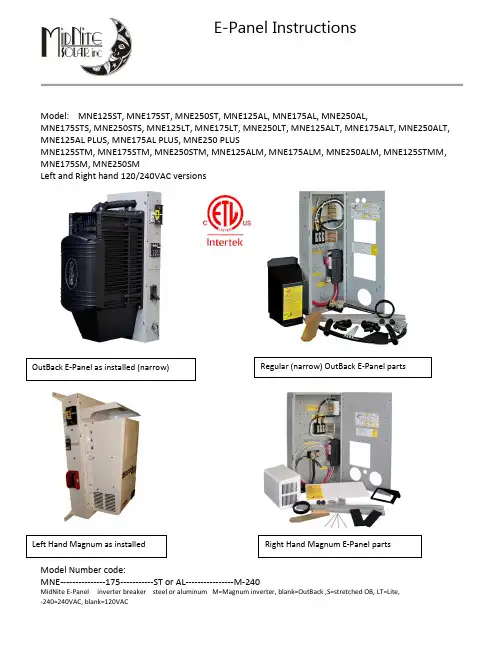
E-Panel InstructionsModel: MNE125ST, MNE175ST, MNE250ST, MNE125AL, MNE175AL, MNE250AL,MNE175STS, MNE250STS, MNE125LT, MNE175LT, MNE250LT, MNE125ALT, MNE175ALT, MNE250ALT, MNE125AL PLUS, MNE175AL PLUS, MNE250 PLUSMNE125STM, MNE175STM, MNE250STM, MNE125ALM, MNE175ALM, MNE250ALM, MNE125STMM, MNE175SM, MNE250SMLeft and Right hand 120/240VAC versionsModel Number code:MNE---------------175-----------ST or AL----------------M-240IMPORTANT SAFETY INSTRUCTIONSSAVE THESE INSTRUCTIONS - These instructions contain important safety and operating instructions for MidNite Solar E-Panels.If you do not fully understand any of the concepts, terminology, or hazards outlined in these instructions, please refer installation to a qualified dealer, electrician or installer. These instructions are not meant to be a complete explanation of a renewable energy system.GENERAL PRECAUTIONSWORKING WITH OR IN THE VICINITY OF A LEAD ACID BATTERY, SEALED OR VENTED IS DANGEROUS. VENTED BATTERIES GENERATE EXPLOSIVE GASES DURING NORMAL OPERATION. FOR THIS REASON, IT IS VERY IMPORTANT THAT BEFORE SERVICING EQUIPMENT IN THE VICINITY OF LEAD-ACID BATTERIES YOU REVIEW AND FOLLOW THESE INSTRUCTIONS CAREFULLY.If service or repair should become necessary, contact MidNite Solar Inc. Improper servicing may result in a risk of shock, fire or explosion. To reduce these risks, disconnect all wiring before attempting any maintenance or cleaning. Turning off the inverter will not reduce these risks. Solar modules produce power when exposed to light. When it is not possible to disconnect the power coming from the Photovoltaics by an external means such as a combiner, cover the modules with an opaque material before servicing any connected equipment.Never attempt to charge a frozen battery.When it is necessary to remove a battery, make sure that the battery bank disconnect breaker is in the off position and that the PV breakers, grid breakers and any other sources of power to the inverter are in the off position. Then remove the negative terminal from the battery first.To reduce risk of battery explosion follow these instructions and those published by the battery manufacturer as well as the manufacturer of any additional equipment used in the vicinity of the batteries. Before installing the battery enclosure, read all instructions and cautionary markings in or on any connected electrical equipment.Avoid producing sparks in the vicinity of the batteries when using vented batteries. Provide ventilation to clear the area of explosive gases. Sealed AGM and Gel batteries do not under normal conditions create explosive gases. Be especially cautious when using metal tools. Dropping a metal tool onto batteries can short circuit them. The resulting spark can lead to personal injury or damage to the equipment. Provide ventilation to outdoors from the battery compartment when installing vented batteries such as golf cart T-105 batteries. The addition of a spill tray is also a good idea.Clean all battery terminals. Very high currents are drawn from the batteries; even a small amount of electrical resistance can result in overheating, poor performance, premature failure or even fire.Have plenty of fresh water and soap nearby in case battery acid contacts skin, clothing or eyes. Wear complete eye and clothing protection. Always avoid touching eyes while working near batteries. If battery acid or battery terminal corrosion contacts skin or clothing, wash immediately with soap and water. If acid enters the eyes, immediately flood with cool running water for at least 15 minutes and get medical attention immediately. Baking soda neutralizes battery acid electrolyte. Keep a supply near the batteries.Do not work alone. Someone should be in the range of your voice or close enough to come to your aid when you work with or near electrical equipment.Remove rings, bracelets, necklaces, watches etc. when working with batteries, photovoltaic modules or other electrical equipment. Power from an illuminated photovoltaic array makes a very effective arc welder with dire consequences if one of the welded pieces is on your person.To reduce the risk of injury, connect only deep cycle lead acid type rechargeable batteries. Other types of batteries may leak or burst, causing personal injury or damage.This equipment is NOT intended for use with life support equipment or other medical equipment or devices.It is the responsibility of the installer to verify compliance with all applicable codes.Before making any connections verify that the circuit breakers are in the off position including the inverter breaker. Double check allwiring before applying power.The MidNite Solar E-Panel comes standard with the basic over-current protection and disconnects required to install your renewable energy system. It can also expand to grow as your needs arise.List of features:● Steel or aluminum chassis with all the r equired openings and knock outs to aid in a NEC compliant system installation● Inverter mounts on a unique hinged door to keep the footprint of the system small as possible● Mounting brackets are included to aid in one person installations● Inverter ba ttery breaker, inverter cables and snap in grommets included*● 500 amp / 50mv shunt included for battery monitoring systems● B us bars are included for additional battery plus, PV plus and battery minus wiring● Heavy duty 175 amp AC power distribution bu s bars included● 50 amp AC input disconnect for generator or utility included, pre-wired (15amp MM series) ● 50 amp AC bypass switch for bypassing inverter circuit, pre-wired (15amp MM series)● Mounting bracket to aid in mounting an OutBack MX60 or MidNi te Classic to the side of the E-Panel*● Battery cable cover to enclose cables external to the chassis***● Inverter and charge controller mounting hardware● Rectangular cut outs for mounting a North American GFCI style AC outlet● Cut outs for mounting up to six additional 13mm wide din rail mount breakers and three ¾” wide panel mount breakers for additional circuits such as PV, wind, hydro or AC distribution ● Plastic snap in conduit and fittings from chassis to inverter for AC, BTS and control circu its (OB versions)● ETL listed to UL and CSA standards* inverter cables and charge control bracket omitted on the LT configurations*** LT versions do not have a cable cover, MM series uses the inverter battery terminal capsThe dimensioned chassis drawings above show the location of the conduit knockouts, mounting holes and mounting brackets.✓Knockouts on the top surface are directly in line with ones on the bottom surface for stacking units vertically.✓Knockouts on the lower end of each side are directly in line with each other for stacking horizontally.✓Steel powder coated units are gray textured. Aluminum powder coated units are gloss white.Door ConfigurationThe standard E-Panel comes as a left hand hinged assembly with breakers on the left side and a left hand hinged door. The door will open to the left over the breakers. If for some reason you need the breakers on the left, but the door to open to the right, then you need the optional right hand door. All breakers can be unmounted and reassembled on the right side of the chassis as is explained in this manual. Right hand E-Panels can be built special at the factory for no additional charge. Changing sides in the field is not a simple task! The left hand hinge is standard because the majority of charge controllers need to be mounted to the right side of the E-Panel. See below.1. Apollo T-80 should be a left hand hinge (heatsink is on the right)3. OutBack MF80 should be left hand hinge (No knock out on the right side of chassis)4. MX60 works equally as well on either side5. WX controller works equally as well on either side6 C40/C60 and Tri-star work equally as well on either side7. Blue Sky has the heatsink on the left, so should use a right hand hinge.See E-Panels explained on the MidNite website for exact part numbers of door options and an explanation of each E-Panel platform. E-Panels Explained will further help you in selecting the applicable E-Panel for your application.The installation begins by selecting a wall. All E-Panels are indoor rated and should not be placed outside unless precautions are made to keep rain and moisture off of the system. The wall must have suitable clearance to open the door with inverter attached. It must also have adequate clearance to operate the breakers and outlets that protrude out the sides. The NEC requires 30” clear on the wall. The E -Panel may be located anywhere within this 30 inches, however make sure you have sufficient room to the side to operate the circuit breakers. Some E-Panel installations may have circuit breakers on both sides. The NEC also requires 36 inches free and clear of obstructions in front of the E-Panel. The 36” clear area in front of all electrical panels is to provide a space to fall back into incase of electrical shock. Each E-Panel with its’ inverter will weigh close to 100 pounds so make sure your wall is adequate for this load. The mounting brackets provided will span studs on 16 inch centers. Mount the top bracket as shown at about 64-68 inches off the floor. If stacking two systems vertically, make sure the breakers fall within the NEC guidelines for height, (lowest and highest allowable). Number 10 screws with back up washers will suffice, but ¼” (6mm) hardwar e provides for a better margin of safety.A little pre-planning here will go a long way towards a successful installation. Battery boxplacement and size also need to be thought out for NEC compliance. The remote display should be approximately at eye level when attached to the E-Panel. Some installation photos below show various ways to install your system.You can make life a little easier by installing additional breakers for charge control, the inverter and such while the E-Panel is still lying horizontal on a table. Do as much of the additionalwiring as possible before hanging the E-Panel on the wall. The following pictures show some of the operations that can be done “on the bench” where access is optimal.Field installed breakers should be torqued to 20 inch pounds, then re-torqued after one hour. This is important! Wires cold flow and sometimes loosen up after the initial tightening, so don’t skip this step. E-Bay is a good source for Sturdevant Richmont torque screw drivers if you are an installer.Breakers such as charge control input and output and DC-GFP can be completely wired prior to installation on the wall. Field wiring is done at the PV, AC and DC terminal bus bars.This picture shows the Outback E-Panel mountedwith two MNEPV63 charge control breakersinstalled and an AC and DC MNSPD Surge ProtectorDevice. The upper mounting bracket can be securedto the wall and then the E-Panel chassis hung ontoit using the keyhole slots in the upper back of thechassis.Before mounting the inverter to the chassis andwith the E-Panel mounted on the wall, complete allwiring that will be coming to and going from the E-Panel. The following pictures give you some idea ofwhat to expect.The picture to the right is a Magnum 240V E-Panel.Notice it has an OutBack OBDC-GFP mounted on the leftside of this right hand hinge unit. There are a total of sixdin rail slots available on each E-Panel for customerconfiguration. This installation has two chargecontrollers. You need a breaker in the PV input and onthe DC output of the charge controller. This took up 4din rail slots for this system. The MidNite DC-GFP takesup 2 din rail slots for the 63 amp version and 2 panelmount knock out slots for the 80 amp version. Neitherone of these would work in this case, so the two circuitOutBack GFP was used. It takes up three slots on theblank plate opposite the din rails. Note the green 6AWGneutral to ground bonding wire in this picture. Theneutral to ground bond is required on all systems perNEC. Note that if this were a power back up system on autility connected home, this bonding wire would not beinstalled as it would already be there on the serviceentrance. On off-grid installations thatemploy a sub panel circuit breaker box, you can make this neutral to ground bond in the sub-panel. It is technically better to make this bond closest to the source of power (the E-Panel), but many electrical inspectors will be looking for it in the sub-panel box. It will work just fine in either location, just make sure you have adequate conductor sizes between the E-Panel and the sub-panel. Do not rely on the hinges for grounding the equipment mounted to the door.The picture to the left shows the charge control bracket suppliedin the E-Panel kit. This one is for a left hand hinged unit, so thecharge control bracket is on the right side opposite the din railbreakers.The charge control bracket supplied works with the OutBackMX60, MF80, MidNite Classic and Xantrex WX charge controllers.The Charge control bracket is secured to the E-Panel with 3 #10 x3/8” sheet metal e one more screw to secure the topbracket of charge controller and a 1” close nipple on the side asshown below. Note tha t it takes three 1” locknuts to mount the controller. One lock nut is used in between the E-Panel side and the charge controller side to act as a spacer. It may help to replace the pan head screws on the side plate with flat head screws in some cases to increase clearance.In addition to the 1” close nipple andthree locknuts, you will need plasticthreaded adapters installed on the endsof the metal threaded nipple. Theseadapters protect wires from coming intocontact with the sharp edges of themetal close nipple.Before wiring the charge controller,determine what size wire and breakerswill be required. The breakers are there to protect the wiring, notthe controller!It is very common to use the MidNite 63 amp din rail breakers for this task. Even if the charge controller is only 30 amps, it can be wired using 63 amp breakers. You will need 6AWG wire to go with those breakers though. If using one of the more powerful 80 amp charge controllers, you will need the MNEDC80 panel mount breakers. These mount on the opposite wall from the din rail breakers. 4AWG wire is required to match up with these 80 amp breakers.The flow path for the PV circuit is as follows:1.The PV + wire comes into the E-Panel and attaches to the PV+ busbar2.The PV- comes into the E-Panel and attaches to the shunt busbar. This is for charge controllers thathave a common PV- and battery- connection, (most are this way). Some charge controllers like the Xantrex XW and the Blue Sky must keep thes PV- and battery- circuits separated. The E-Panels have mounting embosses to accommodate a short white busbar to act as an isolated PV-. Use theMNSBBW for the busbar.3.From the PV+ busbar, use the appropriate gauge red wire (THHN) and connect to the PV+ INbreaker. DC breakers have polarity markings. These may be a + sign or a line and load sign.Although the PV circuit has very limited energy available and thus making polarity issues not too critical, it is best to try to get it right. This is where the fun begins.4. The + (line) marking on the breaker would seem to indicate that you should connect the PV+ tothis terminal since the PV+ is the highest potential in the system. Our testing shows this would be correct. The + side of the breaker needs to be connected to the highest potential per the breaker instructions.5.The - side of the PV in breaker goes to the charge controller PV+ input terminal.6.The output of the charge controller is sometimes marked battery+ This terminal is to connect tothe charge controller output breaker. It will not connect to the + or Line side of the breaker.7.The other side of the breaker, + or line connects to the battery plus busbar. This connection isimportant to observe polarity markings. In the event of a charge controller failure, they quite often short internally, which means they are shorting out the battery. If proper polarity is not observed, the breaker may not open and the wiring will burn up.The factory installed red battery plus bus wire is 4AWG, so it is large enough for all breaker sizes.The diagrams above show 63 amp din rail mount breakers. When 80 amp breakers and or DC-GFPare required, those breakers mount on the wall opposite the din rails. Thereare three panel mount breaker slots to accommodate the 80 ampbreakers and DC-GFP. The 80 amp DC-GFP takes up two of the three slots. The third slot will be used for the output of the 80 amp charge controller. The PV input to an 80 amp charge controller could use a 63 amp din rail mount breaker. There is no additional DC-GFP required when using the MidNite Classic controller. The DC-GFP and arc fault protector are built into the Classic controllers.Mounting the inverterThe 6 x 20mm pan head Philips screws for mounting the inverter are taptite (thread forming). Use one of these 6mm screws to pre-tap threads into the steel doors extruded funnel holes. Aluminum doors have press nuts and do not require tapping. Make sure to install all ¼” star washers to bite through the powder coating.One of the best features of the MidNite E-Panel is that one person can do all the lifting.Slip Tab A into Slot B Install inverter cablesInstall the 3.5” bushing as shown protruding up into the inverter side of the door before routing the inverter cables through the door.More tidbits to digestImportant! Torque din rail mount breakers Installing the breaker cover to 20 in lb. Wait one hour and re-torque .Six locations are available for additional 13mm wide breakers. These breakers would normally be field installed for such things as: solar, wind or hydro charge controllers, DC ground fault protector, AC and or DC distribution center and others. Remove the cut outs for the intended breakers. Each 13mm wide breaker requires removal of two cut outs. 17.5mm wide breakers require removal of three cut outs. It is important to torque the terminals to 20 inch pounds. It is highly recommended to go back over all terminations after an hour and also conduct a pull test.Doors installed,plastic conduit installed, wiring complete. Note the battery cable routing. It is important to route cables so the doors close freely without undue force. The left E-Panel battery cables came from above, but could have come fromYou may be surprised that what you thought was a tight connection actually pulls out with little effort. This is caused be a phenomenon called cold flow. Copper is a relatively soft metal and will continue to move under inadequate clamping pressure. A 20 inch pound of torque takes a lot of strength! Use the supplied UL listed plastic 2” x 6” spacers to separate AC and DC breakers if installed on the same din rail. Barriers are required per NEC between AC and DC circuits.MidNite offers 150VDC breakers in 1,2,3,4,5,6,7,8,9,10,12,15,20,30,40,50 and 63 amps. AC breakers are available in 10,15 and 20 amp sizes. Those breakers carry the UL489 and UL489A branch circuit rating. 30 and 50 amp AC breakers are available in UL1077 listed versions, but are not branch circuit rated.For OutBack installations, install the conduit pieces supplied by routing the three wires through the door and conduit before snapping the fittings into place. Snap the top right angle fitting into place first and then the one in the door. Once the length of wire has beenestablished by opening and closing the door, then cut back the three wires as required and hook up to the terminal block. The conduit in the middle of the inverter is for AC wiring. The outer conduit is for remote and battery temp sense wires.Note: Battery cables in a NEC compliant system requires cable listed for use in residential wiring.For installations requiring the OutBack surge arrestor, see pictures below. Note that this surge arrestor is only accommodated on the Stretched OutBack E-Panel.The flex conduit snaps into the sides of the surge arrestor. You will need to get an adapter to go from the 1” conduit hole in the surge arrestor housing to the ¾” flex conduit. These are readily available at your local electrical supply store or Home Depot/Lowes.This basic wiring diagram is mounted on the inside of the hinged door. Elsewhere in these instructions is a slightly expanded version of the E-Panel wiring diagram. There is an AutoCAD version of the expanded wiring diagram at This is provided so that interested parties may download and modify it to tailor their specific system configuration. When stacking two OutBack inverters, it may be required to add the OutBack PSX-240 autotransformer.OutBack and Magnum horizontal stacked systemsE-Panel parts locator, DoorSupplied insulators to achieverequired separation of AC and DCcircuitsE-Panel parts locator, internal Ground to Neutral connectionMagnum MS4448-AE & MS4024-AE system pre-wire with DC-GFPMNE175SM / MNE250SM Samlex E-Panel wiring.MNE175SM Shown.。


商品说明书翻译商品名称:XXXXX说明书编号:XXXXX发布日期:XXXXX一、产品概述该产品是一款创新型的XXXXX(产品类型)产品,具有XXXXX (产品特点)。
经过多年的研发与改良,本产品已经达到了行业的领先水平,为用户提供了出色的使用体验和优质的功能。
二、产品规格1. 外观特征本产品外观采用XXXXX(材质或颜色),造型精美,质感出众。
尺寸为XXXXX(长度x宽度x高度),重量为XXXXX。
其简约而精致的设计,使其适用于各种场合,为用户带来独特的美感。
2. 技术参数(在此列出产品的各项技术参数)例如:- 电源:XXXXX- 功率:XXXXX- 工作温度:XXXXX- 存储温度:XXXXX- 输入接口:XXXXX- 输出接口:XXXXX- 支持格式:XXXXX3. 主要功能本产品具备以下主要功能:(在此列出产品的各项主要功能)例如:- XXXXX功能:提供XXXXX的效果,满足用户不同需求。
- XXXXX功能:支持XXXXX的操作,方便用户在XXXXX环境中使用。
- XXXXX功能:提供XXXXX的效果,提升用户的体验。
三、使用方法1. 准备工作- 插入电源线,并确保电源供应正常。
- 配置相应的XXXXX设备(如键盘、鼠标等)。
2. 开机与关机- 开机:按下电源按钮,待屏幕显示XXXXX后,即可开始使用。
- 关机:点击XXXXX按钮,在弹出的选项中选择关机,等待系统正常关闭后,断开电源。
3. 操作指南(在此详细介绍产品的各项操作指南)例如:- XXXXX操作:XXXXX- XXXXX操作:XXXXX- XXXXX操作:XXXXX四、安全使用注意事项为了保障用户的安全,使用本产品时请注意以下事项:1. 避免过度使用产品,适当休息并保持良好的工作环境。
2. 请勿将产品暴露在高温或潮湿的环境中,以免损坏电子元件。
3. 当产品出现异常时,请立即停止使用,并联系售后服务中心进行咨询或维修。
4. 请勿尝试拆卸或修理本产品,以免造成损坏或安全风险。

ME super说明书中文版(根据英文版翻译)水平有限,仅供参考,欢迎指正与交流邮箱:enchantedhunter@“ME-Super是Asahi Pentax M series中的佼佼者。
1/2000的最高快门速度,1/125的闪光同步速度,以及EV1-19的测光范围,不但在当时相当先进,就是20多年后的今天,这样的性能也不能算落后。
从型号上看,ME-Super应该是ME的升级版,但实际上,除了外型相似以外,两者在性能上没有多少共同之处。
ME-Super的一个明显与众不同之处在于,它取消了传统的快门调速盘,而代之以上下按键。
然而,不知是因为第一次这样设计,经验不足,还是其他什么原因,宾德竟没有为ME-Super设置取景器以外的快门速度显示装置。
想要知道快门速度到底是多少,必须从取景器里才能看到,这显然太不方便,也可以说是一处明显的败笔。
除此以外,ME-Super似乎再没有什么其他可以挑剔之处了。
”——无忌重要所有宾得镜头及相关系列产品均由宾得公司精心制作。
然而,市面上许多其他公司制作的镜头及相关产品不能保证与宾得产品完全兼容,可能会损坏宾得产品。
因此,宾得公司不承担任何由于使用其他公司的镜头或附件而造成损失的责任。
. 目录基本操作说明“你的ME SUPER 快速教程” (2)部件描述 (4)镜头安装 (6)装入电池 (7)装片和转片 (8)设定胶卷感光速度 (9)曝光模式盘 (10)光圈设置.................................................................:.. (13)对焦和拍摄 (14)在"AUTO"模式下拍摄 (15)曝光补偿 (18)手动曝光.................................:.. (20)握持相机 (26)卸下底片 (27)自动闪光拍摄(AF 200S/AF 160) (28)其他闪光单元 (29)自拍定时/多重曝光 (30)在“Bulb”下使用三脚架/自拍定时拍摄 (31)拍摄指示 (32)景深控制 (34)景深表 (35)测光表耦合范围 (36)红外摄影 (37)使用螺口takumar镜头 (38)光圈全开和自动收缩测光镜头 (40)耐温情况 (41)相机维护 (42)取景器图示 (44)主要规格 (46)欢迎来到我们成长的宾得大家庭!我们知道你即将开始使用你的宾得ME SUPER,我们在2页和3页提供一个“ME SUPER 快速教程”,其中包含“AUTO”模式(也是主要的操作模式)下的基本操作指南,所以你可以马上开始你的摄影之行。

商品说明书翻译商品说明书翻译篇一:产品说明书的翻译产品说明书的翻译说明书主要是用来说明产品的性能、特点、用途、配方及使用方法等,服务对象是普通消费者,所以语言浅显确切,简单明了,讲究科学性和逻辑性。
它的作用旨在指导使用,所以翻译时要一丝不苟,不能有少出入。
由于商品中种类、性质不同,说明的方法。
内容也就不同。
所以在翻译时要针对不同的具体要求,努力使译文所选用词准确明了,行文简洁流畅。
一般来说,日用品说明书在说明产品性能、特点、用途等方面时,往往追求生动活泼,充满溢美之词,旨在激发人们购买、使用产品的欲望。
而药品说明书通常包含成分、主治、用法说明、注意事项、禁忌以及副作用等部分。
翻译时要读懂原文中的专用名词,然后才能准确用词,避免出错。
机械设备说明书通常包括商品特点、用途、规格、性能、结构、操作程序以及注意事项等,语言简单明了。
【例1】娃哈哈儿童营养液娃哈哈儿童营养液是由我厂和浙江医科大学医学营养系共同开发的,含有人体所需的氨基酸、维生素、微量元素等多种营养成分,尤其是对儿童生长发育所缺的钙、铁、锌作了补充,通过国家级新产品鉴定,在国内同类产品中处于领先地位。
配料:蜂蜜、山楂、红枣、枸杞、莲子、米仁、桂圆、核桃等。
成分:每100毫升含量,蛋白质1.5%以上,钙250-300毫克,铁12.5-20毫克,锌12.5-20 毫克。
净含量:每支10毫克,每盒10只,计100毫升。
储藏:本品宜存于阴凉处。
保质期一年,保存期一年半。
食用方法:早晚食用,每次1-2支。
批准文号:浙卫食准字(89)第0004-35号标准代号:Q/JB0201-89 杭州娃哈哈营养食品厂出品,浙江医科大学医学营养系监制。
【译文】 ahaha, a children’s nurishing liquid isc-develped by Hangzhu ahaha Nutritius Fd Prduct Factry and the Dept. f Medical Nutritin f Zhejiang Medical University. The liquid cntains rich amin acids, vitamins and particularly supplies children ith Ca and trace elements such as Fe and Zn essential t healthy grth. It ccupies the leading psitin in the develpment f nurishing prducts and has passed the natin-level evaluatin f nely-develped prducts. Ingredients: hney, hathrn, jujube, lycium, Chinese ltus seed, barley, lngan, alnut, etc. Nutrients: per 100ml: prtein ver1.5%, Ca 250-300 mg, Fe 12.5-20 mg, Zn 12.5-20 mg. Cntents: 10 ampules per case, 10 ml per ample, ttal 100 ml. Strage: T be kept in a cl place. Quality guarantee fr ne year and strage perid ne and a half year. Dsage: 1-2 ampules a day in the mrning and evening. Sanctin N.: Zhejiang Fd Hygiene Permit (89)0004-35 Standard Cde: Q/JB 0201-89 Manufactured by: Hangzhu ahaha Nutritius Fd Prduct Factry Supervised by: Dept.f Medical Nutritin f Zhejiang Medical University 【例2】 Care and Maintenance Yur device is a prduct f superir design and craftsmanship and shuld be treated ith care. The suggestin bel ill help yu prtect yur arranty cverage. · Keep the device dry. Precipitatin, humidity and all types f liquids r misture can cntain minerals that ill crrde electrnic circuits. If yur device des get et, remve the battery and all the device t dry pletely befre replacing it. · D nt use r stre the device in dusty, dirty areas. Its mving parts and electrnic pnents can be damaged. · D nt stre the device in ht areas. High temperatures can shrten the life f electrnic devices, damage batteries, and arp r melt certain plastics. · D nt stre the device in cld areas. hen the device returns t its nrmal temperature, misture can frm inside the device and damageelectrnic circuit bards. · D nt attempt t pen the device ther than as instructed in this guide. · D nt drp, knck, r shake the device. Rugh handling can break internal circuit bards and fine mechanics. · D nt use harsh chemicals, cleaning slvents, r strng detergents t clean the device. · D nt paint the device. Paint can clg the mving parts and prevent prper peratin. · Use a sft, clean, dry clth t clean any lenses (such as camera, prximity sensr, and light sensr lenses). · Use nly the supplied r an apprved replacement antenna. Unauthrized antennas, mdificatins, r attachments culd damage the device and may vilate regulatins gverning radi devices. · Use chargers indrs. 【译文】您的手机为设计优越、做工精良之产品,应妥善维护、保养。
产品说明书范文英文版电子产品说明书——媒体音响英文说明书范例(中英)便携式多媒体音响 Portable Multimedia Acoustics使用说明书User’s Manual专注于完美音质的追求?? Concentrate on perfect soundpursuit?感谢您使用本公司出品的数码产品,为了让您轻松体验产品,我们随机配备了内容详尽的使用说明,您从中可以获取有关产品的介绍,使用方法等方面的知识。
在您开始使用本机之前请先仔细阅读说明书,以便您能正确的使用本机,如有任何印刷错误或翻译失误望广大用户谅解,当涉及内容有所更改时,恕不另行通知。
Thank you for using this digital product of our company. In order to let you experience the product swimmingly, detailed instruction is provided which you can find the product’sintroduction, usage and other information. Before using this product, please read the manual carefully, so that you can correctly use it. In case of any printing or translation error, we apologize for the inconvenience. As for the content change, we are sorry for no further notice.一、产品概述 General Information本机是一款外观小巧,设计精美、携带方便多媒体小音响,适用于家居、户外旅游、办公室等场所,随时随地享受音乐带来的轻松,为您的电脑、数码音乐播放器、手机等视听产品提供超值完美的音质。
商品说明书中英文翻译对照【药物名】对乙酰氨基酚【其他名称】乙酰氨基酚;扑热息痛;退热净;醋氨酚;Acetaminophen;N-acetyl-P-aminophenol【英文名称】 Paracetamol【适应症】用于感冒及流感,发热,减轻中度疼痛如关节痛、神经痛、肌肉痛、头痛、偏头痛、痛经、牙痛等症状。
对阿司匹林过敏或不适应的患者应用本品尤为适宜。
【用法与用量】口服:成人每次300-500毫克,日2-3次。
儿童每日2-3次,每次2-3岁50-100毫克;4-6岁100-150毫克;7-9岁150-200毫克;10-12岁200-250毫克;12岁以上250-500毫克;1岁以下儿童避免使用。
【注意事项】(1)对阿司匹林过敏者一般对本品不发生过敏,但也有因对阿司匹林过敏而发生哮喘的病人中,少部分人在服用本品后发生轻度支气管痉挛性反应,因此,对阿司匹林过敏者慎用。
(2)孕妇和哺乳期妇女慎用。
(3)服用本品后如出现红斑或水肿症状,应立即停药。
【不良反应】一般剂量较少引起不良反应,对胃肠道刺激小,不会引起胃肠道出血。
但也偶可引起恶心、呕吐、出汗、腹泻及面色苍白等不良反应。
长期大量用药,对肝、肾均有损害,尤其是肾功能低下者,可能出现肾绞痛或急性肾功能衰竭。
另外还可发生高铁血红蛋白血症。
【禁忌症】(1)对本品过敏者禁用。
(2)1岁以下儿童及新生儿因肝、肾功能发育不全,应避免使用。
(3)酒精中毒、患肝病或病毒性肝炎时,本品有增加肝脏毒性作用的危险,应禁用。
(4)肾功能不全者禁用。
【限定剂型】片剂,咀嚼片,缓释片,泡腾片,分散片,胶囊剂,口服溶液剂,滴剂,糖浆剂,颗粒剂,泡腾颗粒剂,栓剂。
【药物贮藏】应在阴凉干燥处密闭保存。
【药物配伍】 1、长期饮酒或正在应用其他肝酶诱导剂时,尤其是巴比妥类或其他抗痉挛药的患者,连续使用本品,有发生肝脏毒性反应的危险。
2、长期大量与阿司匹林、其他水杨酸盐制剂或其他非甾体抗炎药合用时(如每年累积用量达1000克,应用3年以上),可明显增加肾毒性的危险。
篇一:化妆品说明书英文翻译产品特点:外界的污染,日光的照射,生活和工作的压力另肌肤干燥粗糙,色素沉浊,暗沉无光泽,各种肌肤问题也随之而来,需要及时为肌肤补充大量水分,促进美白营养成分的吸收。
产品特点:偏黄,暗沉等肌肤问题给生活带来尴尬,需要咋打造清新裸妆的同时给肌肤提供一层保护伞,让你时刻保持自信妆容。
产品特点:质地清透幼滑,迅速渗透,持续给予肌肤充分滋养,让干燥粗糙的肌肤变得明亮润滑,显著改善肤色,用后肌肤清透柔亮,犹如出水芙蓉般水润透白。
蕴含蚕丝蛋白、洛神花和透明质酸,深层保湿,并在肌肤表明形成锁水保湿保护薄膜,增添肌肤活力,持续改善暗沉黑黄肌肤,另肌肤光彩动人。
active white liquid foundation product characteristics:being easy to apply to the skin evenly,it unblocks the pores,shades the blemishes on the fae and increases the brightness and transparency of the skin. containing rich fibroin extract and extract and valued herbal essences,it strenghens the whitening funtion as well as moisturizes the skin ripidly and creates a water -locking membrance to keep the skin tender and smooth with natural white radiance. 肌活盈白粉底液产品特点:自由顺畅延展,改善毛孔堵塞,有效修饰和淡化面部瑕疵,提升肌肤亮度和透明质感;富含蚕丝蛋白及多种名贵草木萃取精华,能提升肌肤美白原动力,快速滋润肌肤,给予肌肤持续保湿,并形成锁水薄膜,令肌肤水润柔滑,时刻呈现自然盈白光彩。