四代grru订货及调测指导v1.0
- 格式:doc
- 大小:12.52 MB
- 文档页数:19

GR系列喷涂机器人远程协助手册资料编号:ZL-GR-004-V1发布日期:2020年1月本手册版权归希美埃(芜湖)机器人技术有限公司所有仅供客户使用,未经授权禁止其他用途使用希美埃(芜湖)机器人技术有限公司安徽省芜湖市鸠江经济开发区万春东路96号电话:400-052-8877CMA希美埃(芜湖)机器人技术有限公司智能化喷涂装备提供商声明感谢您购买希美埃(芜湖)机器人技术有限公司(以下简称“CMA”)喷涂机器人产品。
本文所提及的内容关系到您的安全以及合法权益与责任。
使用本产品之前,请仔细阅读本文,确保已对产品进行正确的设置。
不遵循或不按照本文的说明与警告来操作可能会给您和周围的人带来伤害,损坏CMA 机器人或其它周围的物品。
本文档及所有相关的文档最终解释权归CMA所有。
本手册作为操作指导,但不构成对使用机器人整个应用系统的担保。
因此CMA公司不对使用此系统而可能导致的事故、损害和(或)工业产权相关的问题承担责任。
CMA公司郑重建议:在赋予操作者机器人的使用权限以前,所有参与机器人操作、示教、维护、维修、点检的人员、都参加CMA公司准备的培训课程。
版权与商标本手册版权归希美埃(芜湖)机器人技术有限公司所有,仅供客户使用,未经希美埃(芜湖)机器人技术有限公司书面许可,本部分不能被复制或向第三方披露。
本文档必须保存在机器人的使用寿命期间,损坏或丢失的情况下,你可以订购一个替换的副本。
在机器人被出售或转移到一个新的所有者时,您被要求告知希美埃(芜湖)机器人技术有限公司新的拥有者的地址。
本手册为全套手册的其中一册,所有参与机器人使用、编程、维护、维修、点检的人员,必须经过完整手册的培训,全套手册如下:☐ZL-GR-001-V1:GR系列喷涂机器人《安全手册》☐ZL-GR-002-V1:GR系列喷涂机器人《日常保养手册》☐ZL-GR-003-V1:GR系列喷涂机器人《防爆使用手册》☑ZL-GR-004-V1:GR系列喷涂机器人《远程协助手册》☐ZL-GR-005-V1:GR系列喷涂机器人《IO通讯手册》☐ZL-GR-006-V1:GR系列喷涂机器人《软件编程手册》☐ZL-GR6100-001-V1:GR6100机器人《安装和连接手册》☐ZL-GR6100-002-V1:GR6100机器人《机械维护手册》☐ZL-GR6100-003-V1:GR6100机器人《电气维护手册》☐ZL-GR6100-004-V1:GR6100机器人《电气原理图》本手册及所有相关的手册最终解释权归希美埃(芜湖)机器人技术有限公司所有,希美埃(芜湖)机器人技术有限公司保留随时停止生产或更改设计或规格的权利,如有更新,恕不另行通知。


General InformationGM and GK SeriesNEMA 4, UL Type 4Mounting Installation InstructionsProtection: NEMA 4, UL Type 4, IP66UV protected housingWeather-tight for the harshest indoor andoutdoor conditions71193-00001.A1. Remove the housing cover. Turn the damper shaftuntil the blades are fully closed2. (1) Slip the actuator's universal clamp over thedamper shaft. Make sure that the duct and thecontrols on the cover are accessible. Place theactuator in the desired mounting position.(2) Hand tighten the two nuts on the actuatorsuniversal clamp.3. Disengage the actuator gear train by pressing themanual override button on the actuator.(1) Slide the anti-rotation bracket up under theactuator so it engages the actuator at the center ofthe cutout. Bend the bracket as needed to supportthe rear of the actuator. Secure to duct work withself-tapping screws (No. 8 recommended).4. Loosen the nuts on the universal clamp.Press the manual override button on the actuator and rotate clamp about 5° from the closed position (1/16"to 1/8" between stop and clamp).(1) Tighten the two nuts on the universal clamp with a13 mm wrench. Do not over tighten.5. Install the cover. The damper is now fully closed butthe actuator is 5° from fully closed. This is called"pre-loading" the actuator. When the actuator ispowered and sent to the closed position, it will put its full torque on the shaft compressing the edge andblade seals. This ensures that the damper will meetits leakage rating. The actuator is electronicallyprotected from overload and will not be damaged.Testing the installation without power1. Disengage the gear train with the manual overridebutton and move the shaft from closed to open toclosed. Stroking the damper from fully open toclose, with 5° of actuator stroke left, ensures thereis no binding.2. Correct any problems and reset.NOTES:Ambient temperature: -22°F to 122°F [-30°C to 50°C] Storage temperature: -40°F to 176°F [-40°C to 80°C]These actuators are intended to be connected in the field by a flexible metal conduit except when provided with listed cables suitable for NEMA type 4 application.These devices are not suitable for plenum applications.Standard MountingWiringGMGMWiringWiring2 to 10 VDCVDC/4-20 mABELIMO AmericasUSA Locations, 43 Old Ridgebury Road, Danbury, CT 06810Tel.800-543-9038,Fax800-228-8283,*******************.com1049 Fortunado Loop, Sparks, NV 89436Tel.800-987-9042,Fax800-987-8875,*******************.comCanada Locations, 14/16 – 5716 Coopers Avenue, Mississauga, Ontario L4Z 2E8Tel.800-805-7089,Fax905-712-3124,*******************.comLatin America and The Carribean Customer Service,Tel.203-791-8396,Fax203-791-9139,*******************.com Belimo worldwide: 。
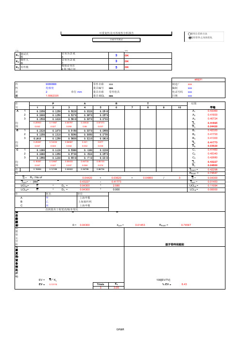
非破坏性测试K 1测试次数必须为 2 或 33OK K 2操作人数必须为 2或 33OK K 3零件数数值必须在 2 和 10之间5OK'01 PSW'!'01 PSW'!A6'01 PSW'!A21'01 PSW'!A54'01 PSW'!H54#REF!零件号9066888零件名称xxx 制造厂xxx 特性轮廓度量具编号xxx编制xxx 公差2单位mm量具名称零件检具 电话号码xxx 总差异 (TV) 1.55623353量具 ECLxxx日期xxx 操作者P A R T 结果编号12345678910A 10.23500.12500.58200.33200.8940A 120.20000.12900.52700.36700.8570A 230.19300.10200.56400.30700.8702A 3平均0.209330.118670.557670.335330.87373X A 范围0.0420.0270.0550.060.037R AB10.23200.10700.54500.33700.8950B 120.18500.13100.58900.30500.8750B 230.19100.12900.56300.32100.8610B 3平均0.202670.122330.565670.3210.877X B 范围0.0470.0240.0440.0320.034R BC10.18600.11200.53600.41600.8230C 120.20600.13900.57300.45200.8970C 230.15900.12300.55400.47400.8340C 3平均0.183670.124670.554330.447330.85133X C 范围0.0470.0270.0370.0580.074R C零件平均0.198560.121890.559220.367890.86736x PART =零件范围R PART =R =R A + R B + R C / No of operators =0.04420+0.03620+0.04860/3R =X DIFF =[Max (X )ABC ] - [Min (X )ABC ] =0.43227-0.41773X DIFF =UCL R =R *D 4 =0.04300* 2.580UCL R =LCL R =R*D 3 =0.04300*0.000LCL R =操作者姓名操作者所在单位A 甲上海申模B 乙上海塞科利C丙上海申模直到量具工程更改/版本变化来自数据表:R =0.04300X DIFF =0.01453R PART =0.74547测量单元分析基于零件间差别可重复性- 设备变化(EV)EV =R * K 1% EV = 100[EV/TV]EV =0.13115Trials K 1% EV =8.433 3.05可再现性 - 鉴定者差别 (AV)AV= [ ( X DIFF * K 2)2 - (EV 2 / nr)](n parts, r trials)% AV = 100[AV/TV]AV=0.01983Oper K 2% AV =1.2732.70可重复性 & 可再现性 (R & R)% R&R = 100[R&R/TV]R&R= (EV 2 + AV 2)% R&R =8.52R&R=0.13264零件差异 (PV)PV=R PART * K 3PartsK 3% PV = 100[PV/TV]PV= 1.5505752.08% PV =99.64总差异 (TV)2.08TV= (R&R 2 + PV 2)#REF!ndc =1.41[PV / R&R]TV= 1.55623All ranges OK ndc=16.48非破坏性测试K 1测试次数必须为 2 或 33OK K 2操作人数必须为2 或 33OK K 3零件数数值必须在 2 和 10之间5OK'01 PSW'!'01 PSW'!A6'01 PSW'!A21'01 PSW'!A54'01 PSW'!H54#REF!零件号9066888零件名称xxx 制造厂xxx 特性轮廓度量具编号xxx编制xxx 公差2单位mm量具名称零件检具 电话号码xxx 总差异 (TV) 1.55623353量具 ECLxxx日期xxx。


DISCONTINUEDDISCONTINUEDFour-Channel, Handheld Data Logger ThermometerWith USB InterfaceL-22U 4 Backlit Displays U R esolution 0.1°C/0.1°F, 1°C/1°F U F unctions: °C/°F/K, Max, Min, Avg, Hold, Rel,Limit, Hi/Lo, Type, Count, Time, Clock, Channel, T1-T2, T3-T4, Backlight, RS232, Rec, Call U N IST-Traceable Certificate of Calibration (No Points)U A uto Power-Off,Low Battery Indication U U SB Interface with Windows Software (Optional RS232 Cable Available)U 10,000 Record Data Logger U C ALL-Fit to Quick- Read Memory Data (50 Pages/Second)U P erpetual Calendar Function U C E-Mark Approval(Conforms to ITS-90)U B attery Life: 550 hr The OMEGA ®HH147U is a rugged, easy-to-use thermometer with4 standard miniature connector inputs. It accepts 7 different thermocouple types and displays all 4 inputs at the same time. It also provides differential temperature measurement readings of T3-T4, as well as individual readings of the 4 inputs. Other features are a low battery indicator, perpetual calendar, and auto power-off.SpecificationsThermocouple Range: Type K: -100 to 1300°C (-148 to 2372°F)Type J: -100 to 1000°C (-148 to 1832°F)Type E: -50 to 800°C (-58 to 1472°F)HH147UType T: -100 to 400°C (-148 to 752°F)Type R/S: 0 to 1700°C (32 to 3092°F)Type N: -100 to 1300°C(-148 to 2372°F)Accuracy (18 to 28°C Ambient):Type K/J/E/T:±(0.1% rdg + 0.7°C) -100 to 1300°C±(0.1% rdg + 1.4°F) -148 to 2372°F Type R/S: ±(0.1% rdg + 2°C) 0 to 1700°C±(0.1% rdg + 4°F) 32 to 3092°FType N:±(0.1% rdg + 1.5°C) -100 to 1300°C ±(0.1% rdg + 3°F) -148 to 2372°FOperating Temperature and Humidity: 0 to 50°C (32 to 122°F), 0 to 80% RH Storage Temperature and Humidity: -20 to 60°C (-4 to 140°F), 0 to 80% RH4 “AAA” batteries, software, USB cable and NIST certificate (no points), and operator’s manual.Ordering Examples: HH147U, data logger thermometer and SPHT-K-6, Type K generalpurpose surface probe. OCW-3, OMEGACARE SM extends standard 1-year warranty to a total of 4 years.These models include a free 1 m (40") Type Free Thermocouple Power Requirement:4 “AAA” batteries (included)Input Protection at Thermocouple Input: 4 Vac/Vdc maximumDimensions (Without Holster): 164 H x 76 W x 32 mm D (6.4 x 3 x 1.25")Weight: Approx 270 g (9.5 oz)No PointsO p t i o n al R S 232OMEGACARE SM extendedwarranty program is available for models shown on this page. Ask your sales representative for fulldetails when placing an order.OMEGACARE SM covers parts,labor and equivalent loaners.HH147U shown with SPHT-K-6, 6"Type K surface probe.。
fluoromax-4使⽤⼿册FluoroMax-4使⽤⼿册⽬录1 FluoroMax-4介绍 (1)2 开关机-校准 (2)2.1 开关机 (2)2.2 校准(推荐校准周期⼀⽉/次) (2)3 功能 (5)3.1.1 发射谱(Emission) (6)3.1.2 激发谱(Excitation) (8)3.1.3 同步谱(synchronous) (9)3.2 Kinetics (10)3.3 3D (11)3.4 Single Point (12)3.5 Anisotropy (13)3.5.1 vs Emission (13)3.5.3 vs Time (15)3.6 Phos (16)3.6.1 Decay by Delay (17)3.6.2 Decay by window (18)3.6.2 Emission and Excitation (19)1 FluoroMax-4介绍FluoroMax-4(以下简称FM-4)是⼀款全⾃动,⼀体化荧光光谱仪。
所有实验数据输出都可以通过连接的电脑输出。
配套的操作软件为FluorEsscence。
⼀台完整的FM-4主要由:1)光源[150W⽆臭氧氙灯光源];2)激发单⾊仪;3)参⽐检测器[R];4)样品池;5)发射单⾊仪;6)信号检测器[R]。
2 开关机-校准2.1 开关机开机- 打开FluoroMax-4电源开关(在仪器右侧⾯),电源键拨到“0”表⽰关机,“1”表⽰开机- 电脑开机- 点击桌⾯FluorEssence软件- 点击仪器会⾃动建⽴端⼝通讯,初始化关机- 关闭FluorEssence,电脑- 关闭FluoroMax-4电源开关建议开机后仪器预热30分钟为宜。
⼀天内勿频繁开关机操作。
例如早上开机,下午需要继续实验,中午可不关机。
⼀天实验结束后,再关机。
2.2 校准(推荐校准周期⼀⽉/次)使⽤仪器前须对设备进⾏校准,保证得到测量数据准确。
校准步骤如下:a 激发端波长校准选择“Spectra”“excitation”使⽤“Monos”(发射波长350nm,狭缝1nm,发射扫描范围200-600nm,步进1nm)选择“Detectors”(输出信号R)输出信号为氙灯的光谱图,对照最⾼峰位在467nmb 发射端波长校准(使⽤建议电阻率在18.3MΩ的纯净⽔)选择“Spectra ”“emission”在“Monos”界⾯输⼊参数(激发波长350nm,狭缝5nm,激发扫描范围365-450nm,步进0.5nm)“Detectors”积分时间0.1s,输出信号“S”。
TEGAM Models 252, 253, and 254 are used for evaluating and inspecting components.These meters provide direct, digital display of inductance, capacitance, resistance,conductance and dissipation. They have the versatility and basic measurement accuracy,0.25%, to satisfy demanding engineering and inspection applications, while being extremely easy to use.Simply push the button for the desired function, set the range and connect to the unknown. True four-terminal connections are ensured by the standard Kelvin Klip®test leads. The measurement is displayed on the large 3.5 digit readout.The Model 253 has all of the above characteristics, an auto-ranging feature, and includes one additional measurement range for C and G.The Model 254 has a 120 Hz testfrequency, which makes it ideal for testing electrolytic capacitors. It has full scale ranges from 2,000 pF to 20,000 µF with 1 pF resolution on the lowest range.An optional battery power pack isavailable on all versions. This allows these meters to be used with line power when available and unplugged when convenient or necessary.Available accessories include the optional Model 1412B Universal Limits Comparator and the Model 2001 Sorting Fixture. Other accessories are presented on the back page of this data sheet.Digital ImpedanceMetersE N T I N S T R U M E N T STHE GLOBAL SOURCE FOR PROVEN TESTAND MEASUREMENT TECHNOLOGY.Prices and specifications subject to change without notice.Static Charge ProtectionDiode and resistor discharge network.Power Requirements100 to 125V or 200 to 250V , 50/60Hz, 4W.DimensionsHeight 10 cm (4 inches).Width 26 cm (10 inches).Depth 37 cm (14.6 inches).Weight3.2 kg (7 lbs) net.* Digit count, same range.** After correction for test lead zero reading 0°C to 15°C and 35°C to 50°C add 0.1 (rated accuracy) °C.Test Frequency1kHz (252 & 253); 120 Hz (254). Optional 100 Hz (254).Measurement Speed4 per second; one second required for first reading after connection to unknown.Connection to UnknownFour-terminal, guarded. Kelvin Klips ®supplied with unit.Display3.5 digits with decimal point; blanked for overload conditions.External Bias 0 to 50VDC.Analog OutputsL, C, R or G, with simultaneous output of D for L and C.Accuracy (15˚ C to 35˚ C)Test Signal252 RangesRange No.0123456L s 200µH 2mH 20mH 200mH 2H 20H 200H C p 200pF 2nF 20nF 200nF 2µF 20µF 200µF R s 2Ω20Ω200Ω2k Ω20k Ω200k Ω2000k ΩG p 2µS20µS200µS2mS20mS200mS2000mSD1.999253 RangesRange No.01234567L s 200µH 2mH 20mH 200mH 2H 20H 200H 200H C p 200pF 2nF 20nF 200nF 2µF 20µF 200µF 2000µF R s 2Ω20Ω200Ω2k Ω20k Ω200k Ω2000k Ω2000k ΩG p 2µS20µS200µS2mS20mS200mS2000mS20SD1.999254 RangesRange No.01234567L s 2000µH 20mH 200mH 2000mH 20H 200H 2000H 2000H C p 2nF 20nF 200nF 2µF 20µF 200µF 2000µF 20mF R s 2Ω20Ω200Ω2k Ω20k Ω200k Ω2000k Ω2000k ΩG p 2µS20µS200µS2000µS20mS200mS2000mS20SD1.999Standard EquipmentKelvin Klips ®43072 Instruction Manual for 25243158Instruction Manual for 25343761Instruction Manual for 25443762±(0.25% +(1 + 0.002R s *) counts)**L s±(0.25% + (1 + 0.001R s *) counts)±(0.25%+(1 + 0.002R s *) counts)±(0.25% +(1 + 0.002R s *) counts)±(0.25% +(1 + 0.002G p *) counts)**C p±(0.25% + (1 + 0.001G p *) counts)±(0.25% +(1 + 0.002G p *) counts)±(0.5% +(1 + 0.004G p *) counts)±(0.25% +(1 + 0.002L s *) counts)R s±(0.25% + (1 + 0.001L s *) counts)±(0.25% + (1 + 0.002L s *) counts)0.25% +(1 + 0.002L s *) counts)±(0.25% +(1 + 0.002C p *) counts)G p±(0.25% + (1 + 0.001C p *) counts)±(0.25% +(1 + 0.002C p *) counts)±(0.5% +(1 + 0.004C p *) counts)±(1% + 0.002) for L or C ≥200 counts; ±(2% + 0.010) for L or C 50 to 199 countsD Voltage C p ,G p 1.0VRMS 0.1VRMS 0.01VRMS Current L s ,R s100mA10mA1mA100µA10µA1µA±(2% + 0.10)SpecificationsLimit Controls -%% deviation lower limit +%% deviation upper limit D dissipation factor upper limitRangesNominal value 00500 to 19999 (corresponds to DPM reading of companion unit).-%-99.9% to 0, -9.99% to 0+%0 to 99.9%, 0 to 9.99%D 0 to 0.999, 0 to 0.0999AccuracyNominal Value ±0.1% of reading(01999 to 19999)±0.3% of reading (00500 to 01999)% limits ±0.5% of full scale D limit±0.5% of full scale Front Panel Lamp IndicationsGO indicates value between- and + % limits, and less than D limit.LO indicates value lessthan - limit HI indicates value greater than + limitD HIindicates factor greater than D limitRelay Contacts (Rear Panel Connections)Four pairs of isolated relay contacts(DPST) close individually in synchronism with front panel lamp indications.Relay Contacts Ratings3 watts dc, 28 volts dc maximum,100 milliamperes; 1 millisecond switch closure time.Gated Relay ClosureGated model operation may be selected by means of a rear panel switch. In this conditionLimits Comparator Relay outputs for Handler operation•Front panel LED for manual sorting •Resolution for nominal 4-1/2 digit •Independent upper and lower limits •Sort by C and D simultaneously •Sorts R,L and G•Operates with 252,253 or 254The Model 1412B is a Limits Comparator used to automatically or manually sort components. When used with a TEGAM Model 252, 253, or 254, it provides either a “GO”, “HI”, or “LOW” indication for R, L,C, or G. The Model 1412B simultaneously sorts for D and C, so there is also a “D HI”indication for this condition.Using the 1412B speeds sorting andminimizes component handling. One method of the acceptance indication is through a rear panel connector which allows for integration into a system by connecting the 1412B to automatic handling equipment.The other indication method is the front panel LED’s. There is also a gated mode,where a comparison is initiated by a control switch and held for an adjustable time, up to two seconds, after release of the switch.Both these features simplify manual use.Resolution of the nominal value is 4.5digits and the limits switches have three digit resolution. The system has two limits ranges,10% and 100% of full scale, allowing for range settings of 0 to 9.99% or 0 to 99.9%.The D limit also has two ranges. The upper and lower limits are set independently,which adds to the outstanding flexibility and accuracy of the system.the relay contacts remain open when a limit is reached, unless closure is initiated by a control switch. Duration of closure, after the control switch is released, is determined by the adjustment of a timing control (two seconds maximum).Input SignalsC, L, R, G analog; D analog; analog common.Internal reference voltage used with TEGAM Model 252, 253, 254 or other instruments,selected by rear panel switch.DimensionsHeight 13.5 cm (5.3 inches)Width 21.6 cm (8.5 inches)Depth (overall) 33 cm (13 inches)Weight3.63 kg (8 lbs) net.Standard EquipmentInterconnection Cable 42855 Instruction Manual for 1412B 42428Options and AccessoriesBattery Powered 252SP2596Battery Powered 253SP2598Battery Powered 254SP2599Dust Cover 43374Sorting Fixture 2001Cable Set for 200143586LINE VOLTAGE 10250/60 Mz100/120220/240FUSE SIZE 1/2A1/4A UNLATCHCalibration & Technical ServicesFor warranty and remedial repair, calibration services and spare parts, or for additional information on TEGAM sales and service offices around the world, contact us at 440-466-6100 (ph) or 440-466-6110 (fx).252.991PGTHE GLOBAL SOURCE FOR PROVEN TESTAND MEASUREMENT TECHNOLOGY.TEN TEGAM WAY • GENEVA,OHIO 44041440-466-6100 • FAX 440-466-6110 • e-mail:***************。
四代GRRU订货及调测指导 V1.0目录一、技术规格 (2)1.1 四代GRRU频段 (2)1.2 单页资料 (2)1.3 四代GRRU设备型号与编码 (4)二、设备连接 (4)2.1、DAU的连接 (4)2.2 DRU的连接 (6)三、设备调测 (7)3.1调测前的准备 (7)3.2网线调测指导 (7)3.3 设备联机界面: (10)附录1: GRRU室外后备供电系统 (11)1 概述 (11)2 主要用途及适用范围 (11)3 产品信息及使用说明 (12)4 主要性能 (13)4.1 保护功能 (13)4.2 电池管理功能 (13)4.3 监控功能 (14)5 机械特性 (14)6 外观 (14)附录2 RRU-OB型光传输旁路单元 (15)1 用途 (15)2功能 (15)3主要性能指标 (15)4 技术指标 (16)5主要技术参数 (16)5.1 光特性 (16)5.2 电缆要求 (16)5.3 机械及环境特性 (17)5.4 系统自动切换场景 (17)6 设备外观及端口定义 (17)7 DRU与光旁路单元的连接 (18)一、技术规格1.1 四代GRRU频段900MHz:下行:935MHz~954MHz,上行:890MHz~909MHz;1800MHz:下行:1805MHz~1830MHz,上行:1710MHz~1735MHz。
注意:1、900M不包括E-GSM频点,也就是例如1000、1010的频点不可设置,如果有则需要移动改频。
2、1800M我们双工是45M,但是技术指标仍然满足移动提出的25M内要求。
1.2 单页资料DAUDRU1.3 四代GRRU设备型号与编码二、设备连接2.1、DAU的连接DAU面板示意图如下图1所示,端口定义如下表1所示。
图1 DAU面板示意图表1 DAU面板端口定义1、射频电缆和接口单元的接法同之前的设备没有差异。
2、在背面接Modem 天线处,多了一个“Modem 信源接口”,因为根据广东移动最新的规范,设备使用无线MODEM 通信时,应具有信源信息。
此时,MODEM 应从基站天馈直接耦合无线信号。
所以我们在开通时,要把MODEM IN 和MODEM OUT 通过机箱内自带的小跳线连接起来即可。
3、锂电池开关。
在开通时需要打开,充电,否则会有“监控模块电池故障告警”。
MODEM IN2.2 DRU的连接DRU的面板示意图如图2所示,端口定义如表2所示。
图2 DRU面板示意图表2 DRU面板端口定义2、四代机均采用一个60W功放,所以不存在通道1单独使用的问题。
3、四代机采用最新的降噪大风扇。
BAT ON/OFF4、锂电池开关。
在开通时需要打开,充电,否则会有“监控模块电池故障告警”。
三、设备调测3.1调测前的准备调测软件版本:OMT-D V2.3四代GRRU暂不支持微波传输。
四代远端只能和四代近端搭配使用。
远端调测准备一条网线3.2网线调测指导联机:DAU可以用RS232接口,DRU必须用网线。
联机时需将笔记本电脑的IP地址与DAU设备的IP地址设置成同一网段,设备出厂默认 IP 地址195.60.16.254。
为避免误操作,该值无法通过OMT更改。
联机类型选择以太网联机。
以太网连接,输入设备的IP地址及端口号。
设备出厂默认IP:195.60.16.254;端口:7025。
如果初始化端口失败还需进行下面的操作,选择通信配置下的IP口配置。
监听端口号设置,范围为7000~65536,确定,端口初始化成功后再联机。
3.3 设备联机界面DAU:与之前设备不同的地方:1、DAU开关量处多了一个“载波跟踪手动触发开关”。
当设置为未触发时,载波跟踪功能关闭,当设置为触发状态时,开启载波跟踪功能,通过设置近端的载波开关来选择开启的载波数,这时候的载波开关近远端是同步的,设置完近端载波开关后就不需要设置远端的载波开关。
当开启载波跟踪功能后,只需要知道基站是几个载波的就打开几个载波通道就可以了,频点设备会在10几分钟内,自动搜索并把它设置进去。
如果遇到扩容则还是需要手动打开通道。
2、设备备份切换开关。
如果近端不用备份功能,则关闭即可。
DRU:与之前设备不同的地方:1、在开关量中,上行噪声抑制开关,要注意打开。
GRRU设备具备上行智能去噪功能,可有效降低对基站的干扰,其门限值可设。
在DRU,将上行噪声抑制开关打开,设置上行噪声抑制门限,范围为-108~-78dBm。
如下图所示。
在设置时不需要设60、120,直接设置准确的值即可。
一般建议设置-105~ -95之间。
附录1: GRRU室外后备供电系统1 概述GRRU射频拉远系统产品已广泛应用,参考基站标准,考虑GRRU设备的退服率,提供后备供电系统将大大提高产品的竞争力。
室外后备供电系统采用备用电池组,平时由市电通过控制模块向电池组供电,市电掉电时由电池组向设备供电,满足特定的系统参数要求。
2 主要用途及适用范围本系统主要用于在市电断电的情况下对GRRU设备进行后备供电,以保证其稳定运行。
系统是按保证单台60W DRU能持续工作12小时设计的,对其他型号的GRRU设备也适用,但是系统持续工作的时间会不同。
系统工作原理框图如图1所示:后备供电系统市电控制器GRRU电池组图1 系统工作原理框图3 产品信息及使用说明产品物料信息如表1所示。
注:1) 物料1为使用机柜的整套供电系统,适用于立地安装和H 杆平台安装。
2) GRRU 后备供电系统采用地窖安装形式时,需要使用物料2和物料3。
每套系统使用6节蓄电池,使用1个控制器。
电源柜与使用一体化机箱的GRRU 设备连接1. 220V 市电分别接入到电源柜的电源输入接口和RRU 设备的“POWER ” 接口。
2. 电源柜直流输出使用4根2.5平方电源线,正负各2根并在一起使用,长度不能超过4米。
用航空接头直接连接到GRRU 设备上的“BAT ”接口即可,并将机箱内电源的BAT 拨至“1”位3. 控制器告警线用航空接头直接连接到GRRU 设备上的“ALARM ”接口。
4. 系统连线示意图如图2:后备电源柜市电220V电输入源直输出流控制器告警POWER ALARMBAT GRRUL N E图2 系统连线示意图4 主要性能 4.1 保护功能系统具有保护功能如表2所示:4.2 电池管理功能电池充放电功能:电源输出两路接口,一路给蓄电池充电,一路作为转换接口。
市电正常情况下,只给蓄电池充电,转换接口无输出,且从转换接口输入的电压不能影响电源的正常工作。
当市电正常时,电源给蓄电池充电;当无市电时,能够自动切换到蓄电池供电,如果蓄电池放电到电压不足时,能够自动保护停止放电。
4.3 监控功能系统提供监控信号,使OMC能监视后备供电系统的工作状态,并且系统中充电控制器一出现故障就能马上向OMC发出告警。
5 机械特性机械特性如表3所示。
6 外观室外供电系统外观如图3所示。
图3 室外供电系统外观附录2 RRU-OB型光传输旁路单元1 用途本次拟制的RRU-OB型光传输旁路单元是在RRU数字射频拉远系统的远端机中实现远端机的光路的自动切换功能,当系统中的一台远端机掉电后,其光路不会中断而能自动切换到它所连接的远端机,以保证整个拉远系统的正常运行。
2功能1)具有光旁路功能;2)能兼容分立和一体化拉远射频远端;3)兼容单模单纤及双纤。
3主要性能指标1)具有光传输旁路功能。
2)良好的光开关特性。
3)切换时间短。
4)标准FC/UPC光纤接口。
5)防水型室外机箱。
4 技术指标技术指标如表1所示。
表1 技术指标5主要技术参数5.1 光特性光特性如表2所示。
表2 光特性5.2 电缆要求航空插头电缆:7芯;用途:光传输旁路单元与DRU连接。
5.3 机械及环境特性设备的机械及环境特性如表3所示。
表3 机械及环境特性表3(续)机械及环境特性5.4 系统自动切换场景系统自动切换场景为所连接的DRU在掉电的情况下。
6 设备外观及端口定义设备外观如图1所示,图1 设备外观图其面板端口定义如表4所示:表4 光传输旁路单元面板端口定义7 DRU与光旁路单元的连接表5 光传输旁路单元端口定义1)需注意当本地DRU被旁路以后,光信号直接从上级设备传输到下级设备。
这时,上级设备到下级设备的光路损耗为从上级到本地及从本地到下级两段光纤及光旁路单元的光插损之和。
因此,需要保证旁路后,下级设备接收到的光功率仍在光器件的接收灵敏度范围之内,才能和上级设备同步。
2)在使用单纤光模块时,需要配对使用。
因此,如图19所示,在旁路后,上级设备和下级设备的光模块仍然要保证是配对的,否则将无法同步。
图2 光旁路系统光模块配对使用示意图3)当接入光旁路单元后,DRU需通过光旁路单元的移位告警线接线来实现移位告警。