示波器MT3500说明书
- 格式:pdf
- 大小:1.04 MB
- 文档页数:53

Kontron User's GuideADA-LVDS-DVIDocument Revision 1.21This page intentionally left blankTable of Contents Table of Contents1User Information (4)1.1About This Document (4)1.2Copyright Notice (4)1.3Trademarks (4)1.4Standards (4)1.5Warranty (4)1.6Technical Support (5)2Introduction (6)3Connector Layout (7)3.1Top Side (7)3.2Connector Functions and Interface Cables (7)4Specifications (8)4.1Functional Specifications (8)4.2Mechanical Specifications (9)4.3Electrical Specifications (10)4.4MTBF (10)4.5Environmental Specifications (11)4.5.1Temperature (11)4.5.2Humidity (11)5Getting started (12)6Chipset (13)6.1LVDS Receiver DS90CF388 (13)6.2PanelLink Transmitter Sil1160CTU (13)7LVDS Interface (14)7.1Connector (14)7.2Connection Table ADA-LVDS-DVI to JILI interface (15)8DVI Interface (16)8.1Connector (16)8.2DDC and Hot Plug Information (17)9History (18)1User Information1.1About This DocumentThis document provides information about products from Kontron Embedded Modules GmbH and/or its subsidiaries. No warranty of suitability, purpose, or fitness is implied. While every attempt has been made to ensure that the information in this document is accurate, the information contained within is supplied “as-is” and is subject to change without notice.For the circuits, descriptions and tables indicated, Kontron assumes no responsibility as far as patents or other rights of third parties are concerned.1.2Copyright NoticeCopyright © 2003-2007 Kontron Embedded Modules GmbHAll rights reserved. No part of this document may be reproduced, transmitted, transcribed, stored in a retrieval system, or translated into any language or computer language, in any form or by any means (electronic, mechanical, photocopying, recording, or otherwise), without the express written permission of Kontron Embedded Modules GmbH.DIMM-PC®, PISA®, ETX®, ETXexpress®, microETXexpress™, X-board®, DIMM-IO® and DIMM-BUS® are trademarks or registered trademarks of Kontron Embedded Modules GmbH. Kontron is trademark or registered trademark of Kontron AG.1.3TrademarksThe following lists the trademarks of components used in this board.IBM, XT, AT, PS/2 and Personal System/2 are trademarks of International BusinessMachines Corp.Microsoft is a registered trademark of Microsoft Corp.Intel is a registered trademark of Intel Corp.All other products and trademarks mentioned in this manual are trademarks of theirrespective owners.1.4StandardsKontron Embedded Modules GmbH is certified to ISO 9000 standards.1.5WarrantyThis Kontron Embedded Modules GmbH product is warranted against defects in material and workmanship for the warranty period from the date of shipment. During the warranty period, Kontron Embedded Modules GmbH will at its discretion decide to repair or replace defective products.Within the warranty period, the repair of products is free of charge as long as warranty conditions are observed.The warranty does not apply to defects resulting from improper or inadequate maintenance or handling by the buyer, unauthorized modification or misuse, operation outside of the product’s environmental specifications or improper installation or maintenance.Kontron Embedded Modules GmbH will not be responsible for any defects or damages to other products not supplied by Kontron Embedded Modules GmbH that are caused by a faulty Kontron Embedded Modules GmbH product.1.6Technical SupportTechnicians and engineers from Kontron Embedded Modules GmbH and/or its subsidiaries are available for technical support. We are committed to making our product easy to use and will help you use our products in your systems.Please consult our Web site at /support for the latest product documentation, utilities, drivers and support contacts. In any case you can always contact your board supplier for technical support.2 Introduction2IntroductionThe ADA-LVDS-DVI is a converter module from LVDS (Low Voltage Differential Signaling) to DVI (Digital Visual Interface). It offers a DVI-D interface with single-link TMDS® and DDC (Display Data Channel) compliance. This converter module can support DVI monitors with resolutions up to UXGA (1600x1200). This converter module is designed for the use with Kontron Embedded Modules GmbH embedded computer boards that support the JILI (JUMPtec Intelligent LVDS Interface) standard. For the support of the complete functionality of DVI (including the DDC support) it is necessary that a video BIOS with DDC auto-detection capability is installed on the embedded computer board. Currently this support is only available for boards equipped with the Intel® chipsets (852/855 or newer). Please contact your technical support for information about available BIOS versions to support this feature.3 Connector Layout 3Connector Layout3.1Top Side3.2Connector Functions and Interface CablesThe table notes connector functions and types.Used Connector DescriptionJ1 DVI Interface MicroCross™ DVI Socket, right angle(Molex 74320-1004)For DVI Monitor cableJ2 LVDS InterfaceFFC 1x40 SG Head2(Hirose FH12-40S-0.5SV)For flat-foil cableJ3 PIC ProgrammingInterface2mm 2x3 pos. For internal use only4Specifications4.1Functional SpecificationsChipsetNational DS90CF388 LVDS receiver (LVDS-to-digital)Silicon Image Sil1160CTU PanelLink transmitter(digital-to-DVI)LVDS interfaceInput to the adapterCompliant with the 40pin JILI standard of Kontron Embedded Modules GmbHDual link LVDS channel with 1 DDCDVI interfaceOutput from the adapterDVI-D interfacesingle link TMDS® with DDC complianceSupported ResolutionsFrom SVGA (800x600) up to UXGA (1600x1200)4.2Mechanical SpecificationsDimensionsPCB Length x Width: 52mm x 40mm (2.05" x 1.57")Module Length with DVI connector: 59mm (2.32”)Minimum Cable Length: 200mm (7.87”)Height on Top: Maximum 10mm (0.39”)Height on Bottom: Maximum 3mm (0.12”)Weight: about 21g (with cable)4.3Electrical SpecificationsSupply VoltagesThe ADA-LVDS-DVI is a +5V-only module. The module’s low-voltage circuitry is supplied by an onboard DC/DC-converter.5V DC +/- 5%Supply Voltage Ripple100mV peak to peak 0 - 20MHzSupply CurrentTypical: 240mAMaximum: 500mA4.4MTBFThe following MTBF (Mean Time Between Failure) values were calculated using a combination of manufacturer’s test data, if the data was available, and a Bellcore calculation for the remaining parts. The Bellcore calculation used is “Method 1 Case 1”. In that particular method the components a re assumed to be operating at a 50 % stress level in a 40° C ambient environment and the system is assumed to have not been burned in. Manufacturer’s data has been used wherever possible. The manufacturer’s data, when used, is specified at 50° C, so in tha t sense the following results are slightly conservative. The MTBF values shown below are for a 40° C in an office or telecommunications environment. Higher temperatures and other environmental stresses (extreme altitude, vibration, salt water exposure, etc.) lower MTBF values.Module MTBF (hours) : > 125.0004 Specifications4.5Environmental Specifications4.5.1TemperatureOperating: 0 to +60 C (*) (non-condensing)Non-operating: -10 to +85 C (non-condensing)Note: (*) The maximum operating temperature is the maximum measurabletemperature on any spot on the module’s surface. You must maintain thetemperature according to the above specification.4.5.2HumidityOperating: 10% to 90% (non-condensing)Non-operating: 5% to 95% (non-condensing)5 Getting started5Getting startedGetting started with the ADA-LVDS-DVI adapter is very easy. For location of the connectors, see Chapter 3: Connector Layout. Take the following steps:Turn off the power supply of your system.Connect the 40pin flat-foil cable coming with the adapter to the ADA-LVDS-DVIprinted circuit board.Connect the other side of the flat-foil cable to the JILI connector of your Kontronmodule or to the corresponding base board equipped with a JILI connector.Connect the DVI monitor to the DVI interface connector of the ADA-LVDS-DVI printedcircuit board.Make sure all your connections have been made correctly.Turn on the power of your DVI monitor and of your system.Enter the BIOS of your Kontron Embedded Modules GmbH board and make sure theJILI interface is activated. See the BIOS chapter of the manual for the correspondingboard you are using for details.Note: Only use the 40pin flat-foil cable delivered with the ADA-LVDS-DVI adapter for connection to the JILI connector. This flat-foil cable has its contacts of both cable ends on the same side. A flat-foil cable delivered with another JILI-adapter usually has its contacts on both cable ends on different sides and may damageyour system.6 Chipset6ChipsetThe chipset of the ADA-LVDS-DVI consists of the National DS90CF388 LVDS receiver and the Silicon Image Sil1160CTU PanelLink Transmitter.6.1LVDS Receiver DS90CF388Supports dual-pixel data transmissionUp to UXGA (1600x1200) resolutionComplies with OpenLDI specification for digital display interfaces40 to 112MHz clock supportConverts 8 LVDS data streams into 48bit of digital data (dual pixel 24bit color)6.2PanelLink Transmitter Sil1160CTUHigh Bandwidth (up to 165 MHz)Resolutions up to UXGAFlexible Interface (24bit with 1 pixel/clock or 48bit with 2 pixels/clock)Low Power (3.3V) core operationHigh Jitter ToleranceTransmitter is compliant with DVI 1.07LVDS InterfaceThe LVDS interface functions as an input to the ADA-LVDS-DVI module. It is available through the flat-foil connector J2 (40 pins). You can connect the LVDS interface to your Kontron Embedded Modules board JILI connector via the 40pin flat-foil cable delivered with this adapter.Note: Only use the 40pin flat-foil cable delivered with the ADA-LVDS-DVI adapter for connection to the JILI connector. This flat-foil cable has its contacts of both cable ends on the same side. A flat-foil cable delivered with another JILI-adapter usually has its contacts on both cable ends on different sides and may damageyour system.7.1ConnectorThe following table shows the pin-out of the LVDS connector.Notes: (*) To protect the external power lines of peripheral devices, make sure that:-- the wires have the right diameter to withstand the maximum available current-- the enclosure of the peripheral device fulfils the fire-protecting requirements of-- IEC/EN 60950.7.2Connection Table ADA-LVDS-DVI to JILI interfaceThe following table gives a better understanding about which signal of the LVDS interface corresponds to which signal of the JILI interface. The pin counting is inverted due to the use of the 40pin flat-foil cable with contacts on one side.8DVI InterfaceThe DVI interface functions as an output from the ADA-LVDS-DVI. This interface is available through the female DVI-D connector J1 (24 pins). You can directly connect a DVI monitor with its male connector to this interface. This interface is a single link TMDS® with DDC compliance.8.1ConnectorThe following table shows the pin-out of the DVI connector.Notes: (*) To protect the external power lines of peripheral devices, make sure that:-- the wires have the right diameter to withstand the maximum available current-- the enclosure of the peripheral device fulfils the fire-protecting requirements of-- IEC/EN 60950.8.2DDC and Hot Plug InformationThe ADA-LVDS-DVI is equipped with an onboard microcontroller. After power-on of the system the /HOTPLUG signal of the LVDS interface goes high for about 10ms and the microcontroller is initialized. After initialization the /HOTPLUG signal goes low and the microcontroller will read in the DDC (Display Data Channel) of the connected DVI monitor. This transaction runs with 10kHz by using the signals DDCDAT and DDCCLK and is completed within 500ms. Then /HOTPLUG goes high again. After this transaction is finished the Kontron Embedded Modules GmbH embedded computer board reads the DDC structure from the microcontroller through the DDC signals of the JILI interface (DDC_DAT and DDC_CLK) with up to 100kHz.In case of the system is already powered up and the DVI Monitor is connected later (Hot Plug), the signal HTPGL on the DVI interface goes high and the microcontroller starts reading the DDC from the DVI Monitor. After all of the DDC data is read the /HOTPLUG signal on the LVDS interface goes high and the embedded computer board reads the DDC structure from the microcontroller.Note: The DDC and Hot Plug feature requires BIOS support. Currently it is only possible to use it on boards equipped with the Intel® chipsets (852/855 or newer). Please contact your technical support for information aboutthe required BIOS version for your special Kontron Embedded Modules GmbH board.9 History 9History1.10 03.01.06 BHO Initial Release1.20 09.09.08 PRO Changed to new Kontron StyleUpdated descriptions due to compatibility to all new Intel Chipsets1.21 14.01.09 PRO Replaced DVI-I with DVI-D in functional specification。

DPST-3500M Digital Pitot Static Test Set “High Accuracy, Exceeds 91.411 FAR Specs, Light Weight for Flight Line Portable Inspections”FAA Certified Repair Station # DZMR112L Cage Code # 3PTA2General InformationThe Model DPST-3500M is a precision, manually controlled, portable, flight line Digital Pitot Static Test Set. This dual channel test set is designed to provide regulated total Pitot (PT) pressure and Static (PS) pressure outputs to simulate Altitude, Airspeed, Vertical Speed, and Mach parameters. The test set can also be used in laboratory environments to calibrate Air Data instruments and various vacuum and pressure gauges. The test set is compact, lightweight and made for harsh Flight Line conditions. Its compact size can fit in the overhead storage compartment of most commercial airliners.• Control valves have a lifetime warranty with a built in protection seat to prevent over tightening of precision valve stems.• Internal pumps produce pressure and vacuum for maintenance free performance.• Performance ranges: Altitude –1500 to 35,000 ft., Vertical Speed +/-20,000 ft./min, Airspeed 0 to 400 knots, and Mach 0 to 1.12.• Sensors automatically perform temperature compensation for extreme flight line conditions. • Smart AC power supply provides a wide range of input voltages: 85 to 264 V AC / 47 to 440 Hz.• Storm Case* is rugged and constructed to meet applicable requirements of MIL-STD-810F and FED-STD-101C and is watertight and pad lockable for theft protection. • Calibration meets or exceeds the published National Institute Standards and Technology (N.I.S.T) specifications. • Test set is shipped with quick disconnect fittings, 2 hoses (15ft /ea) and a power cord (6ft).• Specifications: Exterior dimensions 17”L X 11.70” W X 6.20”H (43.2 x 29.7 x 15.7 cm) Weight 15 lbs. / 6.8 kg*This system is sold as a complete kit ready for use. Includes a current calibration certificate, all connections, and an operation manual.• Certified to perform Pitot Static FAR 91.411 Part 43 Appendix E certifications on General Aviation, Military, Rotary Wing, and Light Sport Aircrafts.• Precision microprocessor based, with Honeywell sensors, accurate to +/- 0.020 % FS.• Display is a sunlight readable TFT 4” inch color, Micro-Graphic Touch panel showing detailed units of measurements including Ft, M, Kts, Km/hr, Mach, Ft/min, m/min, inHg, mbar, and psia.• Main screen displays Altitude, Vertical Speed, Airspeed, and Mach. • Automatic Pitot and Static leak rate modes perform calculations for operator convenience.• Hoses have self- sealing quick disconnect fittings to protect aircraft from pressure loss.Standard Features *Case meets required measurements to fit into overhead compartment in commercial airlines.Weight 15 lbs.DFW Instrument Corporation Tel # 214-217-7600 16445 Addison Road Fax # 214-217-8307 2nd Floor, Hangar 2 Toll Free # 888-500-0075 Addison, TX 75001 To buy, sell, rent or trade-in this product please click on the link below:/DFW-DPST-3500M-Pitot-Static-Test-Set.aspxDigital Manual Pitot Static Test Set DPST-3500M Performance SpecificationsAbsolute Pressure Performance Static Sensor:Range: 0.3 to 40 inHg abs.Accuracy: +/- 0.020 % FS Overpressure: 200 % FS without damagePitot Sensor Range: 0.8 to 80 inHg abs.Accuracy: +/- 0.020 % FS Overpressure: 200 % FS without damageAltitude Performance Range: -1500 ft. to 35,000 ft.Resolution: 1 ft. Accuracy: ±5 ft. @ 0 ft. ±45 ft. @ 35,000 ft.Rate of Climb Performance Range: 100 ft./min. to 20,000 ft./min.Resolution: 25 ft./min.Accuracy: ±10 % of VSI RateAirspeed Performance Range: 10 to 400 Knots Resolution: 1.0 Knots Accuracy: ±2 Knots @ 20 knots ±1 Knots @ 100 knots ±1.5 Knots @ 400 knotsMach Performance Range: 0.0 Mach to 1.12 Mach Resolution: 0.001 Mach Accuracy: 0.020 Mach + 0.1 Mach Pressure Medium Dry AirPressure Connections Quick Disconnects (2 ea.)Safety Seal on SHIP / UUTDisplay Update Rate Once Every 2 Tenths per Second Temperature Compenstion Range 32°F to 122°F 0°C to 50°C Sensors Honeywell Sensors (NIST Traceable)Power Requirement Input Range: 85 - 264 V AC Frequency Range: 47 Thru 440 Hz Environmental Specs Temp. Operating: -20° C to +85° C Temp. Storage: -25° C to +60° C Humidity: 0% to 95% RH Warranty & Calibration Warranty: 2 years (parts & labor ) Calibration: Up to 1 year (yearly calibration suggested ) Certification Calibration / Trace to NIST Accuracy exceeds FAA Regulations FAR 91.411 Specifications Physical Dimensions 17” L x 11.70” W x 6.20” H (43.2 x 29.7 x 15.7 cm)Weight/ Case Specification 15 Lbs / 6.8 Kg MIL-STD-810F • FED-STD-101C • ATA 300Color / Flight Line Yellow Accessories Include: Protection Quick Release Fittings, Hoses, and operation manual. ORDERING INFORMATION/ OPTIONS Mfg. Part Number:DPST-3500M-XXX Option 1: Removable Lid Option 2: 28VDC power- DC Option 3: Altitude EncoderDFW Instrument Corporation 16445 Addison Road 2nd Floor, Hangar 2Addison, TX 75001Tel. # 214-217-7600 Fax # 214-217-8307。

Specifications and Ordering Information 3500/64 Dynamic Pressure MonitorDescriptionThe 3500/64 Dynamic Pressure Monitor is a single slot, four-channel monitor that accepts input from various high temperature pressure transducers and uses this input to drive alarms. The monitor will have one proportional value per channel, bandpass dynamic pressure. The bandpass corner frequencies will be configured using 3500 Rack Configuration Software, along with an additional notch filter, if needed. A recorder output will be provided for control system applications.The primary purpose of the 3500/64M monitor is to provide:1) Machinery protection by continuously comparingmonitored parameters against configured alarmsetpoints to drive alarms.2) Essential machine information for bothoperations and maintenance personnel.Each channel typically conditions its input signal into various parameters called “proportional values”. Alert and danger setpoints can be configured for each active proportional value. SpecificationsInputsSignal: Accepts from 1 to 4 pressuretransducer signals.3 Wire Transducer InputImpedance:2 Wire Transducer InputImpedance:10KΩ>1.5MΩ with 3.5MΩ typicalSensitivity:Dynamic Pressure: 100 mV/psi (1.45mV/mBar)OutputsFront Panel LED’s:OK LED:TX/RX LED:Bypass LED:Indicates when the 3500/64 isoperating properly.Indicates when the 3500/64 iscommunication with othermodules in the 3500 rack.Indicates when the 3500/64 isin the Bypass Mode. Buffered TransducerOutputs:The front of each monitor hasone coaxial connector foreach channel. Eachconnector is short circuitprotected. 1-> All “CascadeMode” does not cascade thebuffered transducer outputs. Output Impedance: 550ΩTransducer Supplies:3 wire: 2 wire: -24Vdc3.3 mA current source @ -22Vdc (nominal)Recorder Outputs: +4 to +20 mA. Values areproportional to monitor fullscale. Individual recordervalues are provided for eachchannel. Monitor operation isunaffected by short circuits onrecorder outputs.Voltage Compliance (current output): 0 to +12 Vdc range across load. Load resistance is 0 to 600 ΩResolution: 0.366uA per bit ±0.25% errorat room temperature, -0.66 to+ 0.70% error overtemperature range. Updatedat 100 mS or less. SignalConditioningDynamic PressureFrequency Response:Direct Filter: “Low Mode” 5Hz. To 4KHz*“High Mode” 10Hz to14.75KHz (Fixed Low Pass)*if no LP filter is chosen, thisextends to approximately5.285KHz.“Low” and “High” filtering modes are options on a channel pair basis. It is possible to select different band pass options on each channel of a channel pair; however, the channels within the pair have to operate in the same filtering mode. Channels 1 and 2 form a pair and channels 3 and 4 form the other pair.In addition, the signal processing can be set up so that ONLY channel 1 input voltage is fed to all four channels. This is “Cascade Mode” (denoted 1->ALL in the 3500 Configuration Software). In “Cascade Mode” the filter mode options are still selected on a channel pair basis. “Cascade Mode” was designed so that one transducer could be used to provide input to four channels for different filtering requirements. This allows four separate bandpass filter options and four separate full-scale ranges to be configured with just one transducer input.The two modes of filtering provide different “qualities” of filtering. LOW MODE:Filter Quality:High Pass (HP): 10-pole (200dB per decade,60 dB per octave)Low Pass (LP):Fixed Low Pass:(LP = none)10-pole (200dB per decade,60 dB per octave)-78 dB minimum attenuationin the stop band.HIGH MODE:Filter Quality:High Pass (HP):Low Pass (LP):6-pole (120 dB per decade,36 dB per octave)-65 dB minimum attenuationin the stop band.Line Refection(Notch)Filter:The line rejection filter hastwo settings, 50 or 60 Hz.Filter response and Centerfrequency selections are validfor both settings.Filter Quality Response:-0.175 dB (98%) of Full Scale; at Center Frequency of +2 Hz And above-0.175 dB (98%) of Full Scale; at Center Frequency of –2 Hz and below-35 dB (1.8%) of Full Scale; from –0.5 Hz of Center Frequency to +0.5 Hz of Center FrequencyAlarmsAlarm Setpoints: Alert and Danger levels areselectable for the directvalues measured by themonitor. All alarm setpointsare set using 3500Configuration software.Alarms are adjustable andcan normally be set from 0 to100% of Full Scale. Theexception is when the fullscale exceeds the range ofthe transducer, in which casethe setpoint will be limited tothe range of the transducer.Alarm Time Delays: Alert:Danger: Alarm time delays can be programmed using 3500 Configuration software.From 1 to 60 seconds, in 1 second intervals.0.1 Seconds minimum and then from 1 to 60 seconds in 0.1 intervals.Proportional ValuesDynamic PressureDirect**This is the primary value for each channel Environmental LimitsTemperature: Humidity: -30º C to 65º C (-22º F to 149ºF) operating.95% non-condensingCE MARK DIRECTIVES: EMC Directives:EN50081-2:Radiated Emissions: Conducted Emissions: EN 55011, Class A EN 55011, Class AEN50082-2:Electrostatic Discharge: Radiated Susceptibility: Conducted Susceptibility: EN 6100-4-2, Criteria B ENV 50140, Criteria A ENV 50141, Criteria AElectrical Fast Transient: Surge Capability: Magnetic Field: EN 61000-4-4, Criteria B EN 61000-4-5, Criteria B EN 61000-4-8, Criteria APower Supply Dip: Radio Telephone: EN 61000-4-11, Criteria B ENV 50204, Criteria BLow Voltage Directives:Safety Requirements: EN 61010-01 Hazardous AreaApprovalsCSA-NRTL/C Class1, Division 2, Groups Athrough DPhysicalMonitor Module (Main Board)Dimensions(Height x Width xDepth):241.3 mm x 24.4 mm 241.8 mm(9.50 in x 0.96 in x 9.52 in). Weight: 0.82 kg (1.8 lbs.).I/O Modules (non-barrier)Dimensions(Height x Width xDepth):241.3 mm x 24.4 mm x 99.1 mm(9.50 in x 0.96 in x 3.90 in). Weight: 0.20 kg (0.44 lbs.).I/O Modules (barrier)Dimensions(Height x Width xDepth):241.3 mm x 24.4 mm x 163.1 mm(9.50 in x 0.96 in x 6.42 in). Weight: 0.46 kg (1.01 lbs.).OrderingInformationDynamic Pressure Module3500/64-AXX-BXXOption DescriptionsA: I/O Module Type 01 I/O Module with InternalTermination02 I/O Module with ExternalTermination’s03 Internal Barrier for 3 wireTransducer04 Internal Barrier for 2 wireTransducerB: Agency Approval Option 00 None01 CSA/NRTL/CExternal Termination (ET) Blocks128015-09 125808-09 Dynamic Pressure ET Block, (Terminal Strip connectors) Dynamic Pressure ET Block, (Euro Style connectors)129649-10 129649-09 Recorder Out ET Block, (Terminal Strip connectors) Recorder Out ET Block, (Euro Style connectors)Cables3500 Dynamic PressureSignal to ET Block Cable129525-AXXXX-BXXOption DescriptionsA: Cable Length 0005 5 feet (1.5 metres)0007 7 feet (2.1 metres)0010 10 feet (3 metres)0025 25 feet (7.5 metres)0050 50 feet (15 metres)0100 100 feet (30.5 metres) B: Assembly Instructions 01 Not Assembled02 Assembled3500 Recorder Output toET Block Cable129529-AXXXX-BXXOption DescriptionsA: Cable Length 0005 5 feet (1.5 metres)0007 7 feet (2.1 metres)0010 10 feet (3 metres)0025 25 feet (7.5 metres)0050 50 feet (15 metres)0100 100 feet (30.5 metres) B: Assembly Instructions 01 Not Assembled02 Assembled Spares140734-05140471-02140482-02132836-0104425545044000370058043400580436005021333500/64 Dynamic PressureModuleI/O Module, InternalTerminationI/O Module, ExternalTermination3500 Dynamic PressureManualGrounding Wrist StrapIC Removal ToolConnector Header, Int.Termination, 8 position, GreenConnector Header, Int.Termination, 6 position, GreenConnector Header, Int.Termination, 12 position, BlueFigures and TablesFront and rear views of the Dynamic Pressure Module1. Status LED’s2. Buffered Transducer Outputs3. I/O Module, Internal Terminations4. I/O Module, External TerminationsData subject to change without notice.© 1999 Bently Nevada Corporation® used in this document are registered marks of Bently Nevada Corporation。

Differential ProbesTDP1500 and TDP3500 DatasheetDifferential active probes provide truer signal reproduction and fidelity for high-frequency measurements. With ultra-low input capacitance and versatile device-under-test connection capabilities, the TDP1500 and TDP3500 Differential-ended Active probes provide excellent high-speed electrical and mechanical performance required for today's digital system designs.Key performance specifications3.5 GHz (TDP3500) and 1.5 GHz (TDP1500) probe bandwidth ≤1 pF (TDP1500) and ≤0.3 pF (TDP3500) differential inputcapacitance200 kΩ (TDP1500) and 100 kΩ (TDP3500) differential input resistance±25 V (TDP1500) and ±15 V (TDP3500) DC + pk AC input voltage >60 dB at 1 MHz and >25 dB at 1 GHz CMRRKey featuresOutstanding electrical performance3.5 GHz and 1.5 GHz bandwidth models - accurate measurementsfor serial and digital applicationsExcellent common mode rejection – reduces measurement errorsin higher common environmentsLow capacitive and resistive loading – maintains signal fidelity andreduces DC biasing interactionsVersatile mechanical performanceCompact probe head size for probing small geometry circuitelementsDUT attachment accessories enable connection to fine-spacedSMDsRobust design for reliabilityEasy to useConnects directly to oscilloscopes with the TekVPI ™ probeinterfaceProvides automatic units scaling and readout on the oscilloscopesdisplayEasy access to probe comp box controls or oscilloscope probe menu display for probe status, setup control, and diagnosticinformationIntegrated Scope/Probe systemDirect connection to and powered from the TekVPI ™ oscilloscope interface (Connects directly to TekVPI scopes without the need ofan external power supply, like many competitors require)Single-button oscilloscope probe menu accessSetup and control from probe comp box or oscilloscope userinterfaceAutoZero - zeros out output offsetRemote GPIB/USB probe control through the oscilloscopeApplicationsDesign, validation, debugging, and characterization of common high-speed serial bus designs:I 2CCAN/LINSPISerial ATAEthernet (GbE)USB 2.0FIreWire (1394b)Signal integrity, jitter, and timing analysisManufacturing, engineering, and testA better measurement toolSpecifically designed for use and direct connection to oscilloscopes with the TekVPI ™ probe interface, the TDP1500 and TDP3500 Differential probes achieve high-speed signal acquisition and measurement fidelity bysolving three traditional problems:DUT loading effects - Are reduced by lower input capacitance and highinput resistanceDUT connectivity - A variety of accessories exist for attaching to smallSMDs, some come standard or recommendedMaximizing of system (oscilloscope and probe) bandwidth - Probing solutions for all measurements for TekVPI interface oscilloscope models up to 3.5 GHzFor the best probe support, download and install the latest version of the oscilloscope software from /software/downloads .DatasheetTDP1500 and TDP3500 Differential probesSpecificationsAll specifications are guaranteed unless noted otherwise. All specifications apply to all models unless noted otherwise.Warranted characteristicsBandwidth (probe only)TDP1500≥1.5 GHz warrantedTDP3500≥3.5 GHz warrantedAttenuationTDP15001X, 10XTDP35005XCMMR>60 dB at 1 MHz, >25 dB at 1 GHzMaximum input voltage(nondestruct)TDP1500±25 V (DC + pk AC)TDP3500±15 V (DC + pk AC)Typical characteristicsRise time (probe only)TDP1500≤265 psTDP3500≤110 psDifferential input capacitanceTDP1500≤1 pFTDP3500≤0.3 pFDifferential input resistanceTDP1500200 kΩTDP3500100 kΩNoise levelTDP1500<≈Propagation delay 5.4 nsCommon mode input rangeTDP1500±7 V (1X)±7 V (10X)TDP3500+5 V to -4VInput offset rangeTDP1500±7 V (10X or 1X)TDP3500±1 V displayedDifferential input dynamic rangeTDP1500±8.5 V (10X)±850 mV (1X)TDP3500±2 VNominal characteristicsRecommended oscilloscope interfaceTekVPI ™ ProbePower requirementsPower requirementsPowered directly by oscilloscopes with the TekVPI probe interface.Physical characteristicsDimensionsWeight1Typical for TDP1500.2Typical for TDP1500.DatasheetTypical characteristicsTDP1500 and TDP3500 Differential probes Ordering informationModelsTDP1500 1.5 GHz Differential Probe with TekVPI™ Probe Interface, Certificate of Traceable Calibration Standard.TDP3500 3.5 GHz Differential Probe with TekVPI™ Probe Interface, Certificate of Traceable Calibration Standard.OptionsLanguage optionsOpt. L0English manualOpt. L5Japanese manualOpt. L7Simplified Chinese manualService optionsOpt. C3Calibration Service 3 YearsOpt. C5Calibration Service 5 YearsOpt. D1Calibration Data ReportOpt. D3Calibration Data Report 3 Years (with Opt. C3)Opt. D5Calibration Data Report 5 Years (with Opt. C5)Opt. R3Repair Service 3 Years (including warranty)Opt. R5Repair Service 5 Years (including warranty)Opt. SILV900Standard warranty extended to 5 yearsAccessoriesTDP1500 standard accessoriesDatasheetTDP3500 standard accessoriesRecommended accessoriesTektronix is registered to ISO 9001 and ISO 14001 by SRI Quality System Registrar.Product(s) complies with IEEE Standard 488.1-1987, RS-232-C, and with Tektronix Standard Codes and Formats.TDP1500 and TDP3500 Differential probesDatasheetASEAN / Australasia (65) 6356 3900 Austria 00800 2255 4835*Balkans, Israel, South Africa and other ISE Countries +41 52 675 3777 Belgium 00800 2255 4835*Brazil +55 (11) 3759 7627 Canada180****9200Central East Europe and the Baltics +41 52 675 3777 Central Europe & Greece +41 52 675 3777 Denmark +45 80 88 1401Finland +41 52 675 3777 France 00800 2255 4835*Germany 00800 2255 4835*Hong Kong 400 820 5835 India 000 800 650 1835 Italy 00800 2255 4835*Japan 81 (3) 6714 3010 Luxembourg +41 52 675 3777 Mexico, Central/South America & Caribbean 52 (55) 56 04 50 90Middle East, Asia, and North Africa +41 52 675 3777 The Netherlands 00800 2255 4835*Norway 800 16098People's Republic of China 400 820 5835 Poland +41 52 675 3777 Portugal 80 08 12370Republic of Korea +822 6917 5084, 822 6917 5080 Russia & CIS +7 (495) 6647564 South Africa +41 52 675 3777Spain 00800 2255 4835*Sweden 00800 2255 4835*Switzerland 00800 2255 4835*Taiwan 886 (2) 2656 6688 United Kingdom & Ireland 00800 2255 4835*USA180****9200* European toll-free number. If not accessible, call: +41 52 675 3777For Further Information. Tektronix maintains a comprehensive, constantly expanding collection of application notes, technical briefs and other resources to help engineers working on the cutting edge of technology. Please visit . Copyright © Tektronix, Inc. All rights reserved. Tektronix products are covered by U.S. and foreign patents, issued and pending. Information in this publication supersedes that in all previously published material. Specification andprice change privileges reserved. TEKTRONIX and TEK are registered trademarks of Tektronix, Inc. All other trade names referenced are the service marks, trademarks, or registered trademarks of their respective companies.11 Feb 2016 51W-20565-6 。

使用说明书VRCM-35使用说明书编号VRCM-35 P3005412-8-029本产品带入欧盟各国时的注意事项Notice : Machine export to Europe本产品不符合自1995年1月1日开始执行的欧盟安全条例――EC指令的要求。
1995年1月1日以后,请不要携带本产品进入欧盟各国。
同样的限制也适用于任何已经签署EEA协议的国家。
如果要把产品调迁或转售至欧盟各国及其他签署了EEA协议的国家时,请提前与我们联系。
This product does not meet the requirements specified in the EC Directives which are the EU safety ordinance that was enforced starting on January 1, 1995. Please make sure that this product is not allowed to bring into the EU after January 1, 1995 as it is.The same restriction is also applied to any country which has signed the EEA accord.Please ask us before attempting to relocate or resell this product to or in any EU member country or any other country which has signed the EEA accord.目录1. 安全注意事项 (2)2. 等离子弧切割安全措施 (2)3. 负载持续率 (8)4. 标准构成和附件 (9)5. 控制操作说明 (10)6. 用户注意事项 (11)7. 运输和安装 (12)8. 外部连接 (13)9. 切割准备 (16)10. 切割作业 (20)11. 切割异常 (26)12. 维护和故障检修 (30)13. 零部件一览表 (38)14. 规格 (40)15. 售后服务 (41)- 1 -- 2 -电击可能导致死亡!触摸带电部位可以导致致命的电击或严重的灼伤。

P o r t a b l e , h a n d h e l d R F p o w e r m e t e r f o r f i e l d a n d l a b u s eR F /M I C R O W A V E3500Portable RF Power MeterSPECIFICATIONSFREQUENCY RANGE:10MHz to 6GHz.POWER RANGE:+20dBm to –63dBm.Max. Power:+23dBm, 5VDC.POWER ACCURACY (at 23°C ±5°C):1+20dBm to +6dBm:±0.24dB, 10MHz to 3GHz (characteristic).2±0.16dB, 3GHz to 5GHz (characteristic).2±0.22dB, 5GHz to 6GHz (characteristic).2+6dBm to –9dBm:±0.26dB, 10MHz to 3.75GHz; ±0.07dB typical.3±0.40dB, 3.75GHz to 6GHz; ±0.07dB typical.3–10dBm to –29dBm:±0.26dB, 10MHz to 3.75GHz; ±0.05dB typical.3±0.37dB, 3.75GHz to 6GHz; ±0.05dB typical.3–30dBm to –40dBm:±0.21dB, 10MHz to 3.75GHz; ±0.12dB typical.3±0.27dB, 3.75GHz to 6GHz; ±0.13dB typical.3LINEARITY (at 23°C ±5°C):±0.10dB, +6dBm to –40dBm.NOISE FLOOR:–63dBm.SWR:1.12:1, 10MHz to 3.75GHz. 1.20:1, 3.75GHz to 6GHz.DISPLAY:4 digits, backlight, auto-shutoff, hold—the most recent reading is shown on the display and is no longer updated.UNITS: dBm, milliwatts.POWER (equipped with auto-shutoff):Unit can be powered from any of these methods:Two 1.5V alkaline AA batteries (not included). Typical battery life: 17.5 hours 4; low battery B port 5.Optional DC power supply 6(3500-PWR).SPEED:Normal:~2 readings per second (> approx. –30dBm).~1 readings per second (≤approx. –30dBm).High-speed:~34 readings per second (> approx. –30dBm).~11 readings per second (≤approx. –30dBm).HOST INTERFACE:USB 2.0 interface with a miniature “B” USB connector 7.AVERAGING:1, 2, 4, 8, 16, and 32 averages.CONNECTORS:RF:Type N male RF connector (50Ωcharacteristic impedance).USB: Miniature “B” USB connector.External Power: Power receptacle (connect optional External Power Supply: 3500-PWR).OPERATING CONDITIONS:Operating Temperature:0°to 50°C (32°to 122°F).Operating Humidity:<80% RH at 35°C (95°F), non-condensing.Air Quality:Compatible for use in a Class 10 cleanroom.SWR (typical)31.181.161.141.121.101.081.061.041.021.00S W R (x :1)Frequency (MHz)100020003000400050006000GENERALSTORAGE CONDITIONS:0°to 70°C (32°to 158°F), 5% to 70% RH, non-condensing.DIMENSIONS:79mm ×134mm ×49mm (3.125 in. ×5.260 in. ×1.925 in.), not including N connector.WEIGHT:0.5kg (1.1 lb.).WARRANTY:1 year; 1 year suggested calibration cycle.EMC:Conforms to European Union Directive 89/336/EEC, EN 61326-1.SAFETY: Conforms to European Union Directive 73/23/EEC, EN 61010-1.NOTESExplanation of how we derived our specs:1.Customer Spec = (x,f) + K(=2) · δ(x,f) + ΔE (x,f,[18°–28°C]) + µwhere:= Mean of the data taken in the frequency range stated (x,f).δ= Standard deviation of the data taken in the frequency range stated (x,f).x = Measured value at test frequencies.f = Frequency range over which data was taken for specification.µ= Measurement uncertainty.ΔE = Change associated temperature variation.18°–28°C = Statistics generated separately at these temperatures and larger statistical value used in setting spec.2.Characteristic (or Expected Value): Characteristic indicates performance that a unit would be expected to exhibit under the following conditions:•Ambient operating temperature of 18°to 28°C, unless otherwise noted •After specified warm up time of 30 minutes.•Does not include measurement uncertainty.This performance is not warranted.3.Typical (mean + 3 standard deviations): Typical indicates performance that all units will meet under the following conditions:•Ambient operating temperature of 23°C, unless otherwise noted •After specified warm up time of 30 minutes. •Does not include measurement uncertainty.This performance is not warranted.4.Typical battery life was measured in the default conditions from the factory at 500MHz with backlight off and no USB communications. With backlight on, typical battery life is 2.5 hours.5.With the USB connected and providing power, and the optional external power disconnected, the Model 3500 will be powered from USB regardless of whether batteries are present.6.If the external power supply is connected, the Model 3500 will be powered by the external supply, regardless of whether USB power or batteries are present.7.The interface is USB 2.0 compliant but with an interface speed of 12Mbps.。
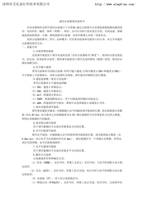
通用示波器使用说明书在家电维修的过程中使用示波器已十分普遍。
通过示波器可以直观地观察被测电路的波形,包括形状、幅度、频率(周期)、相位,还可以对两个波形进行比较,从而迅速、准确地找到故障原因。
正确、熟练地使用示波器,是初学维修人员的一项基本功。
虽然示波器的牌号、型号、品种繁多,但其基本组成和功能却大同小异,本文介绍通用示波器的使用方法。
一、面板介绍1.亮度和聚焦旋钮亮度调节旋钮用于调节光迹的亮度(有些示波器称为"辉度"),使用时应使亮度适当,若过亮,容易损坏示波管。
聚焦调节旋钮用于调节光迹的聚焦(粗细)程度,使用时以图形清晰为佳。
2.信号输入通道常用示波器多为双踪示波器,有两个输入通道,分别为通道1(CH1)和通道2(CH2),可分别接上示波器探头,再将示波器外壳接地,探针插至待测部位进行测量。
3.通道选择键(垂直方式选择)常用示波器有五个通道选择键:(1)CH1:通道1单独显示;(2)CH2:通道2单独显示;(3)ALT:两通道交替显示;(4)CHOP:两通道断续显示,用于扫描速度较慢时双踪显示;(5)ADD:两通道的信号叠加。
维修中以选择通道1或通道2为多。
4.垂直灵敏度调节旋钮调节垂直偏转灵敏度,应根据输入信号的幅度调节旋钮的位置,将该旋钮指示的数值(如0.5V/div,表示垂直方向每格幅度为0.5V)乘以被测信号在屏幕垂直方向所占格数,即得出该被测信号的幅度。
5.垂直移动调节旋钮用于调节被测信号光迹在屏幕垂直方向的位置。
6.水平扫描调节旋钮调节水平速度,应根据输入信号的频率调节旋钮的位置,将该旋钮指示数值(如0.5ms/div,表示水平方向每格时间为0.5ms),乘以被测信号一个周期占有格数,即得出该信号的周期,也可以换算成频率。
7.水平位置调节旋钮用于调节被测信号光迹在屏幕水平方向的位置。
8.触发方式选择示波器通常有四种触发方式:(1)常态(NORM):无信号时,屏幕上无显示;有信号时,与电平控制配合显示稳定波形;(2)自动(AUTO):无信号时,屏幕上显示光迹;有信号时与电平控制配合显示稳定的波形;(3)电视场(TV):用于显示电视场信号;(4)峰值自动(P-PAUTO):无信号时,屏幕上显示光迹;有信号时,无需调节电平即能获得稳定波形显示。
示波器的工作原理时间:2009-05-13 13:42:16 来源:作者:在数字电路实验中,需要使用若干仪器、仪表观察实验现象和结果。
常用的电子测量仪器有万用表、逻辑笔、普通示波器、存储示波器、逻辑分析仪等。
万用表和逻辑笔使用方法比较简单,而逻辑分析仪和存储示波器目前在数字电路教学实验中应用还不十分普遍。
示波器是一种使用非常广泛,且使用相对复杂的仪器。
本章从使用的角度介绍一下示波器的原理和使用方法。
1 示波器工作原理示波器是利用电子示波管的特性,将人眼无法直接观测的交变电信号转换成图像,显示在荧光屏上以便测量的电子测量仪器。
它是观察数字电路实验现象、分析实验中的问题、测量实验结果必不可少的重要仪器。
示波器由示波管和电源系统、同步系统、X轴偏转系统、Y轴偏转系统、延迟扫描系统、标准信号源组成。
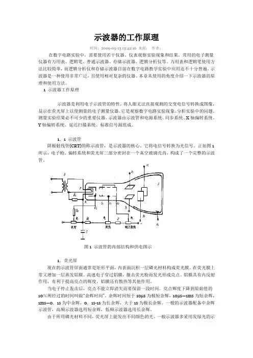
1.1 示波管阴极射线管(CRT)简称示波管,是示波器的核心。
它将电信号转换为光信号。
正如图1所示,电子枪、偏转系统和荧光屏三部分密封在一个真空玻璃壳内,构成了一个完整的示波管。
图1 示波管的内部结构和供电图示1.荧光屏现在的示波管屏面通常是矩形平面,内表面沉积一层磷光材料构成荧光膜。
在荧光膜上常又增加一层蒸发铝膜。
高速电子穿过铝膜,撞击荧光粉而发光形成亮点。
铝膜具有内反射作用,有利于提高亮点的辉度。
铝膜还有散热等其他作用。
当电子停止轰击后,亮点不能立即消失而要保留一段时间。
亮点辉度下降到原始值的10%所经过的时间叫做“余辉时间”。
余辉时间短于10μs为极短余辉,10μs—1ms为短余辉,1ms—0.1s为中余辉,0.1s-1s为长余辉,大于1s为极长余辉。
一般的示波器配备中余辉示波管,高频示波器选用短余辉,低频示波器选用长余辉。
由于所用磷光材料不同,荧光屏上能发出不同颜色的光。
一般示波器多采用发绿光的示波管,以保护人的眼睛。
2.电子枪及聚焦电子枪由灯丝(F)、阴极(K)、栅极(G1)、前加速极(G2)(或称第二栅极)、第一阳极(A1)和第二阳极(A2)组成。


仪器仪表示波器使用说明书仪器仪表示波器使用说明书一、注意事项确认电源电压正常:AC 220V±10%、50/60HZ.为保护仪器请使用仪器背面所指示保险管.最大输入电压:示波器每个输入端口的最大允许输入电压均已标示在面板上,对于Y轴输入电压一般不大于300V(PP+DC).为了保护示波器显示管,尽可能降低亮度,尤其在慢扫描及光束不动的情况下。
注意仪器接地良好。
注意仪器通风良好。
防止周围强磁场干扰。
在作较精确测量时仪器应先预热15分钟。
二、控制部分和接口的概述电源开关(POWER ON):仪器电源总开关。
辉度(INTEN):控制荧光屏上光迹的明暗程度。
聚焦(FOCUS):调节聚焦可使光点圆而小,达到波形清晰。
光迹旋转(TRACE ROTATION):使扫描基线同内刻度水平线平行。
AC GND DC:Y轴放大器CH1、CH2两个通道的输入选择开关,可使输入端为交流耦合、接地、直流耦合。
输入插座(INPUT):CH1、CH2的输入插座,被测信号的输入端。
位移(POSITION):控制光迹在荧光屏Y轴方向的位置。
偏转因数开关(VOLTS/DIV):改变输入偏转因素,一般按1-2-5分档。
微调(VARIABLE):调节显示波形的幅度,一般将其打到校准位置。
⊥:仪器的测量接地装置。
垂直方式开关(VERT MODE):CH1:单独显示CH1输入信号。
CH2: 单独显示CH2输入信号。
交替(扫速高于50us/div时):CH1、CH2两个信号交替显示,一般在信号频率较高时使用。
断续(扫速低于1ms/div时):CH1、CH2两个信号用打点方式同时显示,一般在频率较低时使用。
ADD:使CH1信号与CH2信号相加(CH2极性+)或相减(CH2极性-)。
触发源(SOURCE):触发源选择开关,选择CH1、CH2,外触发(EXT)或电源信号作同步信号。
耦合(COUPLING):耦合方式选择开关,选择DC、AC、HF REJ。
TSI系统调试基本知识本内容将围绕大多数电厂中广泛使用的美国本特利(BENTLY)公司生产的振动检测系统3500为模版,全面讲述系统安装、组态、调试过程及调试中常见问题的处理。
第一节 TSI系统硬件基本知识3500系统能提供连续、在线监测功能,适用于机械保护应用,并为早期识别机械故障提供重要的信息。
该系统高度模块化的设计主要包括:见下图:系统的工作流程是:从现场取得的传感器输入信号提供给3500监测器框架内的监测器和键相位通道,数据被采集后,与报警点比较并从监测器框架送到一个地方或多个地方处理。
3500框架中模件的共同特征是带电插拔和内部、外部接线端子。
任何主模件(安装在3500框架前端)能够在系统供电状态中拆除和更换而不影响不相关模块的工作,如果框架有两个电源,插拔其中一块电源不会影响3500框架的工作。
外部端子使用多芯电缆(每个模块一根线)把输入\输出模块与终端连接起来,这些终端设备使得在紧密空间内把多条线与框架连接起来变的非常容易,内部端子则用于把传感器与输入\输出模块直接连接起来。
外部端子块一般不能与内部端子输入/输出模块一起使用。
1、3500/05系统框架3500框架用于安装所有的监测器模块和框架电源。
它为3500各个框架之间的互相通讯提供背板通讯,并为每个模块提供所要求的电源。
3500框架有两种尺寸:1 全尺寸框架——19英寸EIA框架,有14个可用模块插槽2 迷你型框架——12英寸框架,有7个可用模块插槽电源和框架接口模块必须安装于最左边的两个插槽中。
其余14个框架位置(对与迷你型框架来说是其余7个位置)可以安装任何模块。
2、3500/15电源模块3500 电源是半高度模块,必须安装在框架左边特殊设计的槽口内。
3500 框架可装有一个或两个电源(交流或直流的任意组合)。
其中任何一个电源都可给整个框架供电。
如果安装两个电源,第二个电源可做为第一个电源的备份。
当安装两个电源时,上边的电源作为主电源,下边的电源作为备用电源,只要装有一个电源,拆除或安装第二个电源模块将不影响框架的运行。
3.5 双踪示波器工作原理3.5.1双踪示波器工作原理示波器用来显示电压波形。
一、 工作原理:示波器的核心部件是示波管。
示波管的结构见图3.5.1。
电子枪被灯丝加热后发射电子。
聚焦极将电子枪发射的电子聚焦为极细的电子束,可使波形显示清晰。
加速极上加有较高的正电压,吸引电子脱离电子枪高速运动;显示屏上加有极高的正电压,吸引电子撞击在显示屏面上,使显示屏面涂的荧光材料发光。
垂直偏转板和水平偏转板上加有偏转电压,偏转电压的极性和幅值控制电子束撞击显示屏面的位置。
当偏转电压跟随输入信号变化时,就可以使电子束在屏面上“画“出信号波形。
双踪示波器具有两路输入端,可同时接入两路电压信号进行显示。
在示波器内部,将输入信号放大后,使用电子开关将两路输入信号轮换切换到示波管的偏转板上,使两路信号同时显示在示波管的屏面上,便于进行两路信号的观测比较。
示波器的工作原理框图见图3.5.2。
3.5.2 XJ4241型双踪示波器XJ4241型二踪示波器是一种采用部分集成电路的半导体化便携式示波器,它具有0~10MHz 频带宽度和10mV /div 的垂直输人灵敏度,经扩展最高灵敏度为2mV /div ;扫描时基为0.2μS ~100mS /div .经扩展最高扫速可达40nS /div 。
它具有Y 1、Y 2两个结构相同的垂直输入通道,因此非但能对被测信号进行定性定量测试。
而且能对两个相关信号的相位进行测定。
XJ4241型示波器还具有Y 2-X 的功能,能以垂直输入灵敏度,来显示李沙育图形,由于具备以上功能,XJ4241型示波器能用于电视机、收录机、音频放大器的生产线。
灯丝亦可作为程控机床的检修设备。
一、结构特征外形图(见下页图3.5.3)调节控制机件的作用;(序号与外形对应)1.辉度控制与电源开关:电源开关与辉度电位器同轴。
拉:拉出旋钮电源接通,此时指示灯应发亮,经预热仪器即可正常工作。
辉度:辉度控制,控制显示波形亮度,顺时针方向旋转为增亮,当光点停留在屏幕上不动时,应将亮度减弱或熄灭,以延长示波管寿命。
IP camera tester 网络视频监控测试仪3500操作手册(IPC1.03)⏹感谢您购买工程宝安防监控视频测试仪。
使用前请务必阅读使用说明书,并正确使用。
⏹为了能安全地使用本仪器,请您先仔细阅读使用说明书上的「安全注意事项」。
⏹说明书阅读后请妥善保管,以便随时查阅、参考。
⏹附有的保修凭证或机身的保修封贴,请勿损坏。
⏹使用中遇到问题,或仪器出现损坏时,请与公司技术部联系。
目录一、安全事项--------------------------------------------------------- 1二、IP网络视频监控测试仪简介 ------------------------------------------- 22.1 概述------------------------------------------------------- 22.2 产品特点---------------------------------------------------- 22.3 产品功能---------------------------------------------------- 42.4 产品配件--------------------------------------------------- 102.5 仪表各部位名称和功能: --------------------------------------- 11三、操作说明-------------------------------------------------------- 153.1 电池安装及充电说明------------------------------------------- 153.2 仪器连接--------------------------------------------------- 163.2.1 网络摄像机连接---------------------------------------- 163.2.2 模拟摄像机连接---------------------------------------- 173.3.3 SDI数字摄像机连接------------------------------------- 183.3 功能菜单操作------------------------------------------------ 193.3.1 视频监控--------------------------------------------- 213.3.1.1 云台控制器参数设置------------------------------ 223.3.1.2 色彩及存储设置--------------------------------- 243.3.1.3 视频图像放大----------------------------------- 253.3.1.4 拍照截图-------------------------------------- 263.3.1.5 录像功能-------------------------------------- 263.3.1.6 相片浏览-------------------------------------- 273.3.1.7 录像回放-------------------------------------- 283.3.1.8 视频信号测量*(*定制功能型号见附表)--------------- 293.3.2 图像发生器 TV OUT ------------------------------------ 313.3.3 ONVIF网络摄像机测试----------------------------------- 323.3.4 IP网络摄像机测试-------------------------------------- 393.3.5 SDI摄像机测试 *(*定制功能型号见附表)------------------- 423.3.6 IP地址扫描 ------------------------------------------ 433.3.7 PING连通性测试--------------------------------------- 443.3.8 网线测试器------------------------------------------- 453.3.9 寻线器*(*定制功能型号见附表) -------------------------- 453.3.10 端口闪烁-------------------------------------------- 473.3.11 串口工具-------------------------------------------- 483.3.12 激光功率计*(*定制功能型号见附表)---------------------- 493.3.13 可见红光源*(*定制功能型号见附表)---------------------- 503.3.14 高精度数字万用表*(*定制功能型号见附表)----------------- 523.3.15 视频播放器------------------------------------------ 593.3.16 音乐播放器------------------------------------------ 603.3.17 手电筒--------------------------------------------- 603.3.18 PoE/PSE电压测试功能--------------------------------- 613.3.19 TDR线缆故障测量*(*定制功能型号见附表)----------------- 613.3.20 计算器--------------------------------------------- 643.3.21 浏览器--------------------------------------------- 653.3.22 IPC viewer 移动客户端 ------------------------------ 663.3.23 DC12V电源输出--------------------------------------- 673.3.24 应用工具-------------------------------------------- 693.3.25 APPS工具夹----------------------------------------- 763.3.26 系统设置-------------------------------------------- 773.3.27 更新----------------------------------------------- 803.4 DC12V 1A供电输出-------------------------------------------- 803.5音频测试功能 ------------------------------------------------ 81四、技术参数-------------------------------------------------------- 824.1 技术参数总表------------------------------------------------ 824.2 万用表技术参数---------------------------------------------- 844.3 光功率计技术参数 -------------------------------------------- 864.4可见红光源技术参数-------------------------------------------- 87一、安全事项⏹使用本仪器时,请遵守当地的电气使用相关规则,避免于医院、加油站等不可使用电气的地方使用。
M3500 Industrial Pressure TransmitterThe M3500 is a high accuracy industrial pressure transmitter featuring HART® com-munications and a cast aluminum enclosure for indoor or outdoor use. Typical output accuracy is ±0.035% FS with no effect of temperature from -20º C to +50º C (-4º F to +122º F). Differential, gauge, compound and absolute pressure types are offered in a variety of full scale ranges from 17 PSIA to 3000 PSIG. Outputs include a digital dis-play, 4 - 20 mA (2-wire) with HART® and two SPST opto-switches. Four push buttons located beneath the name plate enable users to manually program and maintain theM3500 for pressure, flow or level applications. Programming can also be accomplished using a HART® communicator. Hardware is included for 2” pipe and wall mounting.Measurement Accuracy: ±0.025% FS including all effects of linearity, hysteresis, repeatability and temperature from -20º to +50º C (-4º to +122º F)Output (mA / V) accuracy: ±0.05% FS including all effects of linearity, hysteresis, repeatability and temperature from -20º to +50º C (-4º to +122º F)Traceability: NIST traceable certification is standardPressure ranges: Lower Sensor Limit (LSL) to Upper Sensor Limit (USL) listed below:Differential [DI]: 0-1, 0-5, 0-15, 0-30, 0-100, 0-300, 0-500 PSIDGauge [GI]: 0-15, 0-30, 0-50, 0-100, 0-300, 0-500, 0-1000, 0-3000 PSIGCompound [CI] (PSIG): -15 to +15, -15 to +30, -15 to +50, -15 to +100, -15 to 300,-15 to +500, -15 to +1000, -15 to + 3000 PSIGAbsolute [AI]: 0-17.4, 0-38.7, 0-100, 0-1000 PSIAAnalog Span LimitDI ,GI, and CI types: 4:1 turndown from Upper Sensor Limit (USL)AI: 2:1 turndown from Upper Sensor Limit (USL)Overpressure LimitsDI: 1000 PSI common mode pressureP1 (High) side only: 3x rangeP2 (Low) side only: 3x range or 150 PSI, whichever is lessGI, CI, AI: 2x Full ScaleDifferential Pressure SensorsStatic Pressure effect on zero: worst case 0.025% URL per 100 PSI. See User’sManual for further details. This effect can be corrected by zeroing the unit at the desiredstatic pressure using an equalizing manifold.Static Pressure effect on accuracy: worst case 0.1% URL per 100 PSI. See User’sManual for details.Orientation effect on zero: installation orientations different from factory calibrationorientation may cause zero offsets up to 1% F.S. on some ranges. Zero the M3500 inits installed position to eliminate zero offset.Temperature SpecificationsOperating Range: -20º to +70° C (-4º to +158° F)Calibrated Range: -20º to +50º C (-4º to +122º F)Storage Range: -20º to +70° C (-20º to +158° F)Temperature effect on output accuracy when above 50º C: standard accuracy +0.005% F.S. per ºCWetted PartsDI: 316L SS and Viton® (Kalrez available, consult factory for other o-ringmaterial options)GI, CI, AI: 316L SSDamping: Exponential damping with user adjustable time constant, 0 (Off) to 60 seconds Sensor Zero: push button or HART®. Differential Pressure units can have zero fully elevated or suppressed within the Lower and Upper Sensor LimitTrims: analog trims, lower sensor trim and upper sensor trim are available via push button or HART®mA output failure modes:Saturation values: 3.9 mA and 20.48 mAFailure values: 3.8 mA and 22.5 mAInternal electronics temperature measurement available from display and via HART®.Pressure Applications: differential, vacuum, compound, gauge or absolutePressure Units:PSI, inches of Water (ref. 20°C, 60°F and 4°C), kg/cm2, MPa, kPa, Pa, mbar, bar, cmof Water (ref. 20°C and 4°C), ft of Water (ref. 20°C, 60°F and 4°C), inches of Mercury@ 0°C, mm of Mercury @0°C, oz/sq in, User defined unit (linear scaling constant from PSI)Flow applications: Square Root (Sq. Rt.) or Laminar Flow Element (Classical B & C method) applications Flow Units: Volume flow: m3, l (liters), yd3, ft3, in3, US gal (US gallons), I gal (Imperial gallons), bbl (barrel), User defined unit Mass flow: lbs, tons, kg, STon (Short Tons), LTon (Long Tons), User defined unit Time: seconds, minutes, hours, days Flow related features: Low Flow cut off value Total flow since last reset Reset total flow register to zero Total non-resettable flowLevel applications: Supports direct head and bubbler type level calculations for linear tanks (vertical), non-linear tanks (horizontal, cylindrical [flat or dished ends] and spherical), and cus -tom strapping tables.Level Units:Height: yards, feet, inches, meters, centimeters, millimeters Liquid volume: cubic inches, US gallons, Imperial gallon, barrels, cubic meters, liters, cubic yards, cubic feet, percent, user defined unit (linear scaling constant) Liquid mass: pounds, tons, kilograms, Short Tons, Long Tons, percent, user defined unit (linear scaling constant)Enclosure: Aluminum casting, designed to NEMA 4 requirementsFront and rear caps secured with set screws Dimensions: 5.12” L x 3.56” Dia. x 4.57” H Weight: 2.7 – 3.0 lbsConduit connections: ½” NPT (female), 2 ea. 1 permanent plug includedPressure Manifold: Material: 316L SSPressure connection(s): 1/8” NPT (female) for all pressure sensor types1/8” NPT(M) x ¼” NPT(F) 316L SS adapter(s) are included Differential Pressure models are available with a standard 2 port manifold or optional 4 portmanifold with bleed/flushing connections and plugs (5/16 – 24 SAE/MS J1926)( 5.12 )Display – 2 line LCD Upper line for up to 5 numeric characters Lower line for up to 6 alphanumeric characters Update rate: 3x per second Floating decimal pointDisplay orientation to be specified with order Standard, Clockwise [90º], Reverse [180º], or Counterclockwise [270º] orientationName plate:The name plate on top of the M3500 provides model and serial numbers plus other specifications. Loosen the lower right screw and slide to access the keypad.Keypad:Located under the name plate, the keypad consists of 4 arrow keys used for manualprogramming and trim adjust-ments (sensor zero, lower sensor trim, uppersensor trim and analog trims).1.62” x 0.75” viewable areaStandard Display bottom connection(s)Clockwise (90˚) Display right hand connection(s)Reverse (180˚) Display top connection(s)CCW (2700˚) Displayleft hand connection(s)DI Manifold - standardDI Manifold - with optional bleed/flushing ports & plugs(Recommended for liquid DP Applications)GI, CI and AI Manifold permanent plug in P2 sideElectrical connections:Six (6) position terminal block for• Loop Power & Communication (2- wire)• Two opto-coupler SPST switches• 1.3 mm diameter holes suitable for 16 – 25gauge solid or stranded wireCase grounding screwTest tabs for mA outputComm tabs for HART® communicationsPower: 16 – 45 V DCLoad Curve: Maximum Loop Resistance = (50 * Power Supply Voltage) - 800Note: HART communication requires a minimum loop resistance of 250Ω (21V DC) Outputs:4 – 20 mA (2-wire)HART® digital protocolTwo each, solid state opto-coupler SPST switchesRating: DC, 0.25 mA max., Von = 0.7 V DC, Voff = 5.4V DCCertifications: CE MarkEnvironmentalHumidity Limits: 5 – 95% RHShock, Operating: 30 g, halve-sine, 11mSec pulse (tested in accordance withIEC-60068-2-27)Vibration, Sinusoidal, Operating: 2g peak acceleration at 5-500 Hz (tested in accordance with IEC-60068-2-6)Vibration, Random, Operating: 6g rms acceleration at 5 to 2000 Hz (tested inaccordance with IEC-60068-2-64)Mounting2” pipe mount with bracket, 316SS, for horizontal orvertical orientation mountings. Includes 2” U-bolts andhardware (zinc plated CS).Standard bracket accommodates pipe mount or surfacemountingStandard AccessoriesP/N Z1065 NIST Certificate with dataP/N Z9A683-1 1/8” NPT(M) x ¼” NPT(F) adapter (1 each for AI, CI and GI models), 316L SS P/N Z9A683-2 1/8” NPT(M) x ¼” NPT(F) adapters (2 each for DI models), 316L SSP/N Z9P120 Mounting bracket, 316 SSP/N Z9A64 Mounting hardware kit, zinc plated CS, U-bolts (2 ea.), nuts, washersP/N Z9R86 User’s ManualOptional Accessories, Certifications and TestsP/N Z1089 3-valve equalizing manifold kit, 316L SS, c/w pre-bent tubing & tube fittings P/N Z9P130 Material CertificationP/N ZA33559 Hydrostatic Pressure TestP/N Z1077 Tag, wired SSOrder Options -DI0001-DI0005-DI0015-DI0030-DI0100-DI0300-DI05000 TO 500 PSI Differential, Isolated, 2-port manifold -GI0015 -GI0030-GI0050-GI0100-GI0300-GI0500-GI1000-GI3000-CI0015 -CI0030-CI0050-CI0100-CI0300-CI0500-CI1000-CI3000-AI0017-AI0038-AI0100-AI1000Flushing Port option - DI sensors only -00Standard pressure manifold-04Display Orientation -0For bottom pressure connections (Standard, 0 degrees)-1-2-3Other Options -A -B -CM3500-CI0100-00-0-ACType & Range -15 TO +300 PSIG Compound, Isolated Description (M3500, universal mounting bracket, hardware, NIST cert and manual) 0 TO 300 PSI Differential, Isolated, 2-port manifold 0 TO 15 PSI Gauge, Isolated 0 TO 1000 PSI Gauge, Isolated -15 TO +15 PSIG Compound, Isolated 0 TO 30 PSI Gauge, Isolated 0 TO 500 PSI Gauge, Isolated 0 TO 100 PSI Absolute, Isolated 0 TO 50 PSI Gauge, Isolated 0 TO 100 PSI Gauge, Isolated 0 TO 1000 PSI Absolute, Isolated 0 TO 3000 PSI Gauge, Isolated-15 TO +50 PSIG Compound, Isolated -15 TO +100 PSIG Compound, Isolated -15 TO +500 PSIG Compound, Isolated -15 TO +1000 PSIG Compound, Isolated 0 TO 17 PSI Absolute, Isolated -15 TO +3000 PSIG Compound, Isolated 0 TO 38 PSI Absolute, Isolated M35000 TO 300 PSI Gauge, Isolated -15 TO +30 PSIG Compound, Isolated 0 TO 1 PSI Differential, Isolated, 2-port manifold 0 TO 5 PSI Differential, Isolated, 2-port manifold 0 TO 15 PSI Differential, Isolated, 2-port manifold 0 TO 30 PSI Differential, Isolated, 2-port manifold 0 TO 100 PSI Differential, Isolated, 2-port manifold DI sensors only - optional 4 port bleed/flush manifold, recommended for liquid service 3-valve manifold & tubing, installed, 316SS, 1/4" NPT(F) connections, SWP = 3000 PSIG (Z1089)Factory Configuration (customer must complete and submit M3500 Configuration Sheet Z9R90 with order)For top pressure connections (Reverse, 180 deg)For left hand pressure connections (CCW, 270 deg)For right hand pressure connection (Clockwise, 90 deg) 3-valve manifold (316SS) & tubing (brass), installed, 1/4" NPT(F) connections, SWP = 3000 PSIG (Z1089-1)。