36章引气AMM概述
- 格式:doc
- 大小:54.00 KB
- 文档页数:3
飞机健康管理(AHM)系统在航空运行中的应用和作用0 引言自国货航波音机队引进波音公司飞机健康管理(AHM)系统以来,针对该系统在公司航班运行和维修生产中不断得以应用,极大的促进了国货航机队的安全健康发展,并在航班运行保障过程中起到了重要的保障作用。
1 飞机健康管理系统(AHM)介绍波音飞机健康管理系统(以下简称AHM系统)是波音公司开发的一个自动化的维护-决策支持系统。
它实时收集和处理飞机在飞行中的实时数据,并通过系统自动对数据进行监控和分析,决定并作出对飞机系统和主要部件的当前和计划维护工作;同时针对影响飞机放行或需要采取的维护措施,AHM系统提供相关的维护文件链接,包括客户飞机的最低设备清单(MEL)、外形缺件清单(CDL)、放行缺件指南(DDG)、零件目录手册(IPC)、线路图手册(WDM)、故障隔离手册(FIM)和飞机维护手册(AMM)等。
飞机维护工程师通过登陆网址就可以浏览到AHM系统提供的飞机各系统相关技术数据(如图1),通过对数据进行监控和分析,确保对公司机队飞行和技术状态进行实时监控。
AHM系统为航空公司提供实时的跟踪工具,可识别飞机潜在的问题和故障,并将故障后维修转变为主动、有计划、及时的检修项目。
飞机健康管理系统为航空公司提供实时的飞机状态信息和维修信息,能够快速有效的帮助维修工程师提供可靠的放行指南、正确的排故方案并帮助工程师处理潜在的技术问题,使飞机在确保安全的前提下放行,降低了航班延误的发生,同时尽可能减少被迫停场,提高了公司机队的可用率水平和代表公司运行品质的重要指标——航班正点率(如图2)。
飞机健康管理系统是独立工作系统,是预先提出故障的预测性的解决方案,可以纳入航空公司现有的维修和工程体系;同时,通过在航空公司运行/维修控制中心的广泛使用,对提高公司飞行安全也起到了极大的积极作用。
2 飞机健康管理系统(AHM)功能AHM系统具有实时监控、性能分析、勤务监控等多种功能。
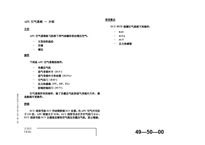

参考《飞机构造系统》(宋静波编著)飞机气源系统气源系统的功用是提供具有一定流量、压力和温度的增压空气到用压系统。
民航飞机的气源主要来自燃气涡轮发动机压气机、APU或地面气源。
可用于空调和增压系统供气、大翼前缘及发动机前缘整流罩热空气防冰、发动机的起动、水箱及液压油箱增压气源、驱动液压泵等。
飞机正常飞行时的气源是由发动机压气机引气提供的,一旦一台或两台发动机引气系统失效时,在一定飞行高度下可由APU供气,有的飞机在起飞阶段也使用APU引气进行空气调节,以减轻发动机在起飞过程中的负荷。
双发飞机一般有两个独立的引气系统,中间由隔离活门隔断。
需要时两个系统可以连通。
APU引气通过引气关断活门和单向活门引气到气源总管。
在隔离的一侧(或两侧)设有地面气源接头。
参阅B737飞机维护手册(AMM)36章气源系统原理图。
它主要由三个部分组成:即高(中)压引气、预冷器控制和调压关断活门(PRSOV)部分。
它有两级引气口:中压引气口和高压引气口,分别来自发动机高压压气机的两级。
正常情况下(较高发动机功率时),空气从中压引气口引出,此时高压级活门关闭。
当发动机在低功率下工作时,中压引气压力不足,则高压级活门自动打开,由高压引气口供气。
在中压引气出口处安装有单向活门,可以防止空气从高压级向中压级倒流。
来自发动机压气机的引气经过调压关断活门(PRSOV),它主要有三个作用:(1)限制活门下游压力;(2)限制下游温度;(3)提供引气关断功能。
PRSOV通过调节活门的开度,控制下游的压力,下游最大压力一般控制在40~50psi (275~344kPa)。
PRSOV活门及控制器本身并不具有专门的限温装置,它的限温控制是通过减小PRSOV 活门的开度来实现的。
当预冷器下游(热路)温度过高时,PRSOV活门会逐渐关小。
随着PRSOV活门的逐渐关小,通过此活门的流量也随之逐渐减小,使流经预冷器的热空气流量减小,而相对来讲,预冷器的冷却空气流量增大,使热空气在预冷器内得到更充分的冷却,因此可以阻止热空气温度的进一步升高,以达到限温的目的。


1飞机引气的来源有哪些?(C)A 地面空调、发动机、APUB 发动机、APUC 地面气源、发动机、APU2飞机1号发动机的PRV(pressure regulating valve)在以下哪种情况时不会被关闭?(B)A 1号发动在启动时。
B 2号发动在启动时。
C 飞机使用APU引气时。
3PRV(pressure regulating valve)下游出口压力为(A)。
A 48psi。
B 35psi。
C 根据用户指令由BMC给出相应的值。
4 当飞机使用APU引气时,引气交输活门选择器在自动位,以下描述正确的是(C)。
A 引气交输活门和PRV打开。
B 引气交输活门和PRV关闭。
C 引气交输活门打开而PRV关闭。
5 当飞机发动机工作在正常转速时,发动机引气的来源是(C)。
A 高压级引气。
B 中压涡轮引气。
C 中压级压气机引气。
6 以下对FAV(Fan Air Valve)的描述正确的是(A)。
A 调节进入空气预冷器的冷空气,以便调节发动机引气温度。
B 排出外涵道多余气体,防止外涵道超压。
C 该活门的位置由用户的状态决定。
7 对于PRV的控制以下描述正确的是(C)。
A 由相应的BMC监视并控制其开关状态。
B 由相应的BMC监视其状态并由装在其上游的ThS控制其开关。
C 由相应的BMC监视其状态并由装在其下游的ThS控制其开关。
8 在正常情况下,当中压级压力达到多少时,飞机使用中压级引气。
(A)A 40psiB 80psiC 35psi9 当HPV和IPV之间的相互转换失效时,HPV将如何动作?(B)A 当HPV上游压力大于185psi,BMC会自动关闭HPV。
B 当HPV上游压力大于185psi,HPV受气动控制会自动关闭。
C 当HPV上游压力大于185psi,PRV会控制HPV自动关闭。
10 ThC用于监控哪一处的温度?(C)A 预冷器的进口温度。
B PRV的出口温度。
C 预冷器出口温度。
11 以下对PRV描述正确的是(C)。
A320飞机排故方法实用汇编------ 东航宁波分公司机务部前言随着A320飞机的逐步引进和运行,我飞机维修部在该机型的使用和维护中已经积累并总结了一定的经验,这些都在实际工作中起到了良好的作用。
为了更进一步提高维修人员的业务水平,并使信息资源得到充分的共享利用,在部领导的关心和指导下,我们依据2002年以来东航历次质量/技术分析例会的纪要提炼并编制了《A320飞机排故方法实用汇编》。
旨在借鉴先进经验,开拓排故思路,提高维护能力。
但它不能够也不可能代替各种维护手册。
此《汇编》目前只收录了东航机队的故障实例,信息量和内容还有待进一步完善。
因此本《汇编》采取活页以及按章节排页的形式,以便于不断地修订和插页,力求广录博引,萃取精华,对其丰富充实。
由于编辑时间仓促,难免有错误和不足之处,请读者提出指正意见。
东航宁波分公司机务部技术室2004年九月东方航空宁波分公司机务部 CHINA EASTERN AIRLINESATA 21 章 空调系统(1) 故障现象: VENT SKIN VALVE FAULT ECAM 警告排故结果和分析: 更换AEVC 计算机注意事项和措施: 评估相应的SB 决定是否对AEVC 进行改装升级(2)故障现象: 电子舱鼓风机故障信息和电子舱通风故障信息, 排故结果和分析:更换电子舱通风系统气滤,检查正常。
注意事项和措施:电子舱通风系统故障是目前A320机队存在的多发性故障,已引起多次重要事件和航班不正常。
电子舱通风系统故障反映较多的为吹风扇和蒙皮进口活门故障。
对电子舱吹风扇故障,主要是由于电子舱通风气滤堵塞导致通过气滤的气流减少并使得气滤下游气流压力降低,最终由压力电门17HQ 或19HQ 以及管路温度传感器26HQ 触发产生吹风扇故障警告。
因此,当空中出现故障时在地面往往可能并无故障出现,AEVC 地面测试正常。
电子舱通风故障,当BLOWER 和EXTRACT 按钮放超控位时,EXTRACT 活门处于部分打开状态位正常状态,这种情况下的返航是没有必要的。
AMM 手册的使用说明及注意事项飞机维护手册(AMM )作为机务的工作指南,是航线维护及机库维修中使用最为频繁的一本手册,所以正确的阅读、理解和使用AMM 是一名机务人员的基本要求及必备素质。
但通过对近期接连发生的几起不安全事件的分析表明,部分机务对AMM 的手册的理解和使用还存在一些问题,针对此问题MD-Q 编制此使用说明及注意事项。
一、 使用说明1. AMM 手册的结构按照ATA100号规范,各种民用航空器技术资料都可按其内容根据下列三种情况予以编号: (1) 系统/章号“系统”是由相关机件所组成的,用以完成某种特定的功能的集合每一系统在手册中都称为“章”,每章都指定一个编号作为这一标准编号中的第一组号码。
(2) 子系统/节号“子系统”是“系统”中的某一部分,每一个系统可以由几个子系统共同组成,每一个子系统还可以再划分为几个子系统。
每一子系统拥有各自的编号作为标准编号规范中的第二组号码。
ATA 对章节的规定到子系统一级,也就是说,第二组号码的第一位(3) 组件/目号“组件”是指组成“系统”、“子系统”并完成一定功能的组件及各个单独的线路、管路等。
“组件”所编的“目号”成为标准编号规范中的第三组号码。
这一编号由组件的制造厂家自行编排除此之外维护手册根据自身的性质,按照工作的不同内容,将页码分成不同的区段。
页码的第一位是功能位,代表该页码段的工作内容和性质。
页码的后两位是顺序的页码,表明的是每页的排序,由于AMM 手册的基本单位是页,因此页码对AMM 手册的查询是一个关键点。
5081--系统/章号子系统/节号组件/目号通讯音频综合REU•201-299 维护措施Maintenance Practices“维护施工”是勤务、拆卸/安装、调整/测试、检查/检验、清洁/喷漆、经批准的修理和适当处的特定步骤的组合。
当要求的维护程序不长并相对简单时,以上的组合组成到“维护施工”标题下。
•301-399 勤务Servicing勤务程序包含在其他维护工作通常要求的程序中,勤务程序应该是独立的,并可常规化或可恢复。
摘要本文基于可靠性维修理论针对波音767飞机引气系统中HPSOV(高压关断活门)非计划拆换进行分析和研究。
HPSOV非计划拆换的分析内容主要包括以下几个方面:首先运用AMM (飞机维护手册)手册对波音767飞机HPSOV的工作原理、工作特性、结构及安装进行分析研究。
然后运用可靠性理论分析波音767飞机HPSOV 的非计划拆换原因。
通过分析得出引起HPSOV非计划拆换的原因主要是(1)机队中的某些飞机长期使用老型号的陈旧部件;(2)机务维修人员没有客观地按照《飞机维护手册》做出有效的排故措施;(3)飞机引气系统的日常维护工作不够充分。
根据得到的分析结果提出以下工程维护措施:(1)建议使用2002年12月以后生产的新型改进版本的HPSOV;(2)建议部件使用时间超过3433小时后,拆修或者更换HPSOV;(3)建议每个部件安装使用1000小时后,进行各主要部分管接头的密封检查,润滑HPSOV的活门体,清洁该活门的位置电门。
关键词:波音767,引气系统,HPSOV,非计划拆换Analysis and Disposal of Unplanned Replacement for Boeing767’s HPSOVABSTRACTBased on reliability concept of maintenance, this thesis analyzes and studys the reason of unplanned replacement for HPSOV(High Pressure Shot Off V alve), which is a part of the Boeing 767’s air bleed system.The contents about HPSOV unplanned replacement analysis were: First, do the investigate on the work principle, job characteristic, the structure and installation of HPSOV on Boeing 767 according to the AMM(Aircraft Maintenance Manul). Next, through reliability concept to analyze the reason of HPSOV unplanned replacement of Boeing 767. Through the analysis, we can found that the reasons of HPSOV unplanned replacement. (1) Some planes in their team were using the old and demoded hardware. (2) The service man did not arrange the problem according to the AMM impersonality.(3)Daily maintenance for the air bleed system was not enough.According to the analysis results from above, some project maintenance methods can be got: (1)Advice using the new style HPSOV made in Dec.12, 2002. (2)Some parts after 3433 hours used should be replaced or repaired the HPSOV. (3)Every part after 1000 hours used must be checked on the airproof of the main duct connector. And lubricate HPSOV's valve body. And clean the position switches in this part.Key words: Boeing 767,air bleed system,HPSOV,unplanned replacement波音767飞机HPSOV非计划拆换分析与处理徐银生 02810160 引言伴随着全球经济一体化的进程以及中国经济体制改革的进行,近年来民航业发展突飞猛进。
目录第第一部分航线维修记录常用语句 (1)......检查发现/报告故障. (1)参考/按..更换(件)......,检查 / 测试正常 (1)检查发现...故障,按...保留,...号/类别,同意放行 .. (2)按...,更换...件,测试正常,撤消 / 关闭...保留 (2)遭遇冰雹/鸟击 (2)为判断...故障/因为航材缺件,对串...件,测试... (2)更换......件,试车检查.. (2)第二部分飞机/故障基础语句 (3)飞机概况 (3)方位描述 (4)航材 (4)故障描述 (4)解决故障 (6)第三部分 (7)各章节单词和故障描述 (7)A T A21空调 (7)A T A24电源 (10)A T A25设备和装饰 (11)A T A26防火 (15)A T A27飞行控制 (16)A T A28燃油 (19)A T A29液压 (20)A T A30防冰/防雨 (21)A T A32起落架 (22)A T A33灯 (24)A T A35氧气 (27)A T A36气源系统 (28)A T A38水和废物 (29)A T A49辅助动力装置 (30)A T A52门 (32)A T A53机身 (34)A T A55安定面 (34)A T A56窗 (34)A T A57大翼 (35)A T A71动力装置 (35)A T A73发动机燃油和控制 (37)A T A74点火 (38)A T A75发动机空气 (38)A T A76发动机控制 (38)A T A77发动机指示 (39)A T A78排气 (40)A T A79发动机滑油 (41)A T A80起动 (42)1 / 44第一部分航线维修记录常用语句……检查发现/报告故障……1.航后:检查发现左后航行灯不亮。
After Flight(AF ):Find L AFT position light is not on.2.检查发现右前轮磨损超标。
GeneralThe pneumatic system gets compressed air from the pneumatic air sources and supplies the compressed air through ducts to the user systems. The ducts are installed in the fuselage, the belly fairing and the wings.The control of the pneumatic system is usually automatic. Bleed-Air Monitoring Computers (BMCs) control the automatic function. The BMCs are installed in the avionics compartment. There is one BMC for each engine.You can also control the system manually. The pushbutton and selector swit ches on the overhead panel 30VU in the cockpit, control the manual function.You can monitor the operation of the pneumatic system on the ECAM System Display (SD). The pushbutton switches on the overhead panel 30VU have no indication when the system operates correctly.** ON A/C 004-100, 201-400A. Pneumatic Air SourcesThe aircraft engines, the APU or a ground air source can supply compressed air to the pneumatic system. The distribution system supplies the compressed air from the different sources to the user systems.(1) The aircraft engines are the primary source of compressed air in flight. The air is bled fromthe 5th (IP) or 9th stage (CFMI engines) of the engine High Pressure (HP) compressor. The engine bleed air is temperature and pressure controlled.(2) The Auxiliary Power Unit (APU) is the primary source of compressed air on the ground. Theair is bled from the APU load-compressor module. You can also use the APU to supply bleed air to the user systems during flight. The APU can supply bleed air up to an altitude of 20000 ft. (6096 m).(3) A ground air source is an alternative to the APU for the supply of compressed air on theground. There is one High Pressure (HP) ground connector installed on the aircraft. You can use it to let the ground air source supply compressed air to the pneumatic system.B. User SystemsThe pneumatic system supplies the subsequent aircraft systems:- t he wing ice protection system (Ref. 30-11-00),- t he air conditioning system (Ref. 21-00-00),- t he engine starting system (Ref. 80-00-00),- t he hydraulic reservoir pressurizing system (Ref. 29-14-00),- t he pressurized water system (Ref. 38-42-00),- t he nacelle anti-ice valve (servo pressure) (Ref. 30-00-00)System DescriptionThe pneumatic system has the subsequent subsystems:- distribution (Ref. 36-10-00),- indicating (Ref. 36-20-00).A. DistributionThe distribution system supplies the bleed air from the different bleed air sources to the user systems.The distribution system has the subsequent subsystems:- t he engine bleed-air supply-system (Ref. 36-11-00),- t he APU bleed-air supply and crossfeed system (Ref. 36-12-00),- the ground compressed-air supply-system (Ref 36-13-00),- environment protection (Ref. 36-14-00).B. IndicatingThe indicating system has the subsequent subsystems:- p ressure and temperature monitoring (Ref. 36-21-00),- l eak detection (Ref. 36-22-00).The indicating system monitors:- t he pressure and the temperature of the bleed air in the ducts,- t he valve position of the different valves,- t he overheat detection sensing-elements which are installed on or near to the ducts.Power SupplyThe pneumatic system gets electrical power from the DC system of the aircraft. The DC system supplies 28 V DC through the circuit breakers 2HA1, 2HA2, 3HA1 and 3HA2 to:- t he Bleed Air Monitoring Computers,- t he relays of the AIR COND overhead panel,- t he FIRE overhead panel,- t he pressure transducers.Operation/Control and IndicatingThe operation and control of the pneumatic system is usually automatic. The BMCs monitor and control the automatic operation. You can also control the system manually from the cockpit. The pushbutton and selector switches on the overhead panel 30VU control the manual function.You can monitor the operation of the pneumatic system on the BLEED page of t he SD. The APU page of the SD also shows some information related to the APU bleed air. The pushbutton switches on the overhead panel 30VU have no indication when the system operates correctly. If there is a failure, the failure data are available on the E CAMEngine/Warning Display (EWD), the SD and the Centralized Fault Display System (CFDS).The pushbutton switches on the overhead panel 30VU can also show some failures. (Ref.36-20-00).Bite TestThe Centralized Fault Display System (CFDS) gives the maintenance crew a maintenance aid. It permits to test the BMC or to get the maintenance data of the bleed air system.The CFDS gets the information through the Centralized Fault Display Interface Unit (CFDIU) (Ref. 31-32-00) from the BMC. The Multi-purpose Control Display Units (MCDU) in the cockpit displays this information in clear text.。