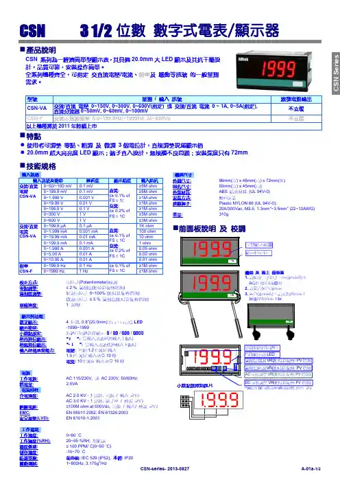
CS1-VA 数显电压电流表
- 格式:pdf
- 大小:933.31 KB
- 文档页数:7
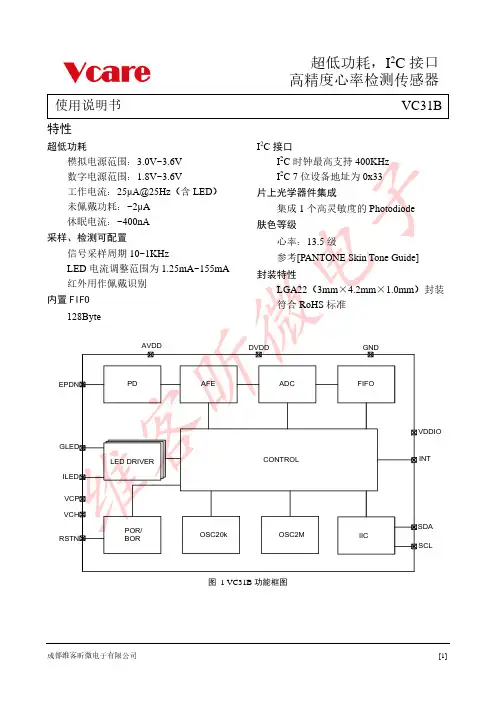
使用说明书特性I2C接口超低功耗Array内置图 1 VC31B功能框图1修订历史表 1 修订历史2表 2 VC31B引脚说明3 推荐应用电路a、bc、d LDOe、VC31B模拟电源典型供电电压为3.3V,要求LDO 输出电源纹波峰峰值应小于40mV; 另外要求LDO 的负载瞬态响应:电流从1mA 瞬变为100mA 时,LDO 的输出稳定时间应小于50μs,稳定压降应小于10mV。
注:给心率模组供电的LDO 输出不能有大于 3.6V 的持续电压以及脉冲电压。
单位图5 推荐回流焊温度曲线7图10 硅胶框隔光辅料尺寸图布局说明及注意事项:1、此布局针对运动版方案,因此对漏光处理较为严格: a 、 要求VC31B 与镜片的距离不超过0.1mm (最好为零配);b 、图6、8中VC31B 周围的黑色虚线框为我司开模设计的硅胶框隔光辅料,隔光辅料尺寸如上图10所示,硅胶框应轻度挤压,以保证隔光的效果; 2、图7、9丝印外部为不界定边框,要求内部开窗与上图一致;3、除VC31B 与LED 的布局固定外,其余阻容元器件在布局时需注意不能放置在隔光辅料区域内,以免影响硅胶安装效果(VC31B 周围0.6mm 以内不放置任何元器件);;4、丝印镜片要求如下:a 、 推荐镜片窗口透光率:90%以上;b 、推荐镜片窗口透射波长:400至 1000nm ;c 、 镜片厚度不超过0.5mm ,推荐质硬、不易形变的玻璃或者亚克力;5、以上图示外如需任何结构变动,需与维客沟通,经由维客评估之后方可保证性能;6、 手环设计要求:a 、 心率、血氧凸台建议 1.0mm ;b 、 如对手环运动心率准确性要求较高,那么手环整体重量要求不超过 36g (不含表带);6、结构设计要点VC31B说明书8LED性能参数及辅料说明VC31B心率芯片对Green、IR的光效及压降要求如下表所示,可根据下表LED参数成都维客昕微电子有限公司[11]。
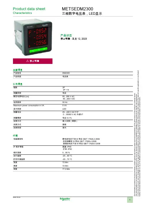
Product data sheetCharacteristicsMETSEDM2300三相数字电压表,LED显示产品状态停止销售 : 五月 12, 2023i 停止销售主要信息产品短名DM2300产品类型电压表补充信息极数3P3P + N测量类型电压额定电源电压 [Us]85...265 V AC 85...265 V DC电网频率50 HzMaximum power consumption in VA5 VA显示类型LED测量电压25…450 V AC P-P0…35000 V AC 外部VT测量精度电压 0.3 %安装方式嵌入安装(暗装)安装方式面板安装类型室内环境电磁兼容性静电放电抗干扰 III 符合 GB/T 17626.2 2006 抗快速瞬变 III 符合 GB/T 17626.4 2008 浪涌放电抗干扰 III 符合 GB/T 17626.5 2008IP 保护等级面盖: IP40 灯体: IP20相对湿度5…95 %运行温度-20…60 °C贮存环境温度-20…70 °C宽度72 Mm高度72 Mm深度77.3 MmT h e i n f o r m a t i o n p r o v i d e d i n t h i s d o c u m e n t a t i o n c o n t a i n s g e n e r a l d e s c r i p t i o n s a n d /o r t e c h n i c a l c h a r a c t e r i s t i c s o f t h e p e r f o r m a n c e o f t h e p r o d u c t s c o n t a i n e d h e r e i n .T h i s d o c u m e n t a t i o n i s n o t i n t e n d e d a s a s u b s t i t u t e f o r a n d i s n o t t o b e u s e d f o r d e t e r m i n i n g s u i t a b i l i t y o r r e l i a b i l i t y o f t h e s e p r o d u c t s f o r s p e c i f i c u s e r a p p l i c a t i o n s .I t i s t h e d u t y o f a n y s u c h u s e r o r i n t e g r a t o r t o p e r f o r m t h e a p p r o p r i a t e a n d c o m p l e t e r i s k a n a l y s i s , e v a l u a t i o n a n d t e s t i n g o f t h e p r o d u c t s w i t h r e s p e c t t o t h e r e l e v a n t s p e c i f i c a p p l i c a t i o n o r u s e t h e r e o f .N e i t h e r S c h n e i d e r E l e c t r i c I n d u s t r i e s S A S n o r a n y o f i t s a f f i l i a t e s o r s u b s i d i a r i e s s h a l l b e r e s p o n s i b l e o r l i a b l e f o r m i s u s e o f t h e i n f o r m a t i o n c o n t a i n e d h e r e i n .包装单位Unit Type of Package 1PCENumber of Units in Package 11Package 1 Height7.2 CmPackage 1 Width7.2 CmPackage 1 Length7.7 CmPackage 1 Weight300.0 G可持续性欧盟ROHS指令符合欧盟ROHS声明WEEE该产品必须经特定废物回收处理后弃置于欧盟市场,绝不可丢弃于垃圾桶中。
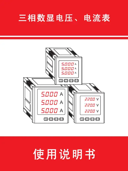
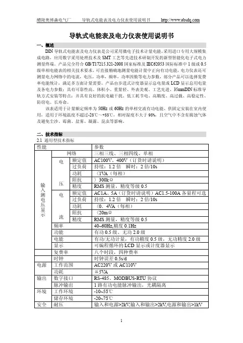
使用说明书三相数显电压、电流表使用说明书安装、使用产品前,请阅读使用说明书一、技术参数1.1 测量范围1.1.1 三相数显电压表直接测量:AC0~600V外附装置:AC0~9999KV(外附 */100V电压互感器)1.1.2 三相数显电流表直接测量:AC0~10A外附装置:AC0~9999A(外附 */1A、5A电流互感器)1.2 准确度:±0.5%FS±1个字1.3 采样速率:约1次/s1.4 显示方式:三排四位LED数码管有效值显示1.5 显示分辨力:末位数一个字1.6 输入回路功率:每相<0.5VA1.7 供电电源:AC 220V±10%,50/60Hz(其他值时请在订货时说明)1.8 供电电源功耗:<3VA1.9溢出指示:显示字符“HHHH”1.10 报警输出:上下限报警采用两组继电器输出,触点容量AC250V/2A,DC30V/2A1.11变送输出:可设置为DC0~20mA或DC4~20mA,准确度±0.5%FS,与信号输入及供电电源端口之间电气隔离1.12 变送输出负载电阻:≤500Ω1.13通讯接口:RS485串行通讯,采用MODBUS_RTU1.14 工作环境:温度 -10~50°C,湿度≤85%RH的无腐蚀性气体场合注:通讯输出、报警输出、变送输出为附加功能,订货时用户须加以说明。
二、安装与接线仪表外形面框尺寸壳体尺寸安装开孔尺寸120×120方形96×96方形80×80方形72×72方形48×48方形1201209696808072724848宽高深宽宽高高1101109090747466664444939393938311111192927676686845452.1 安装开孔尺寸(单位:mm)2.2 安装方法根据仪表尺寸在上表中选择对应的安装开孔尺寸,在安装屏上开一个孔,将仪表嵌入孔内,四个夹持件放入仪表壳体的夹持槽内,用手推紧即可。

C31-VA直流伏安表技术参数C31型直流伏安表,直流伏特表,直流安培表,直流毫安表,直流微安表,直流伏安表,直流毫伏表:C31型0.5级直流电表(以下简称仪表)是磁电系张线支承携带式指示电表,供在直流电路中测量电流和电压用。
仪表按使用条件属于P组,适用于周围环境温度为23±10℃及相对湿度为25%-80%的条件下工作。
直流伏安表C31-VA共有一种规格:0-1.5/3/7.5/15/30A,3/15/30/75/150/300/600V。
外观尺寸:220×170×100mmC31型0.5级直流伏安表技术参数表:型号测量范围C31-μA直流微安表0-10μA0-20μA0-50μA100/200/500/1000μA 150/300/750/1500μAC31-mA直流毫安表1.5/3/7.5/15mA5/10/20/50mA100/200/500/1000mAC31-A直流安培表7.5/15/30/75/150/300/750mA,1.5/3/7.5/15/30A 0-25-50-100A(特规)C31-V直流伏特表0.045/0.075/3/7.5/15/30/75/150/300/600V 0-1.5/15/150/1500V0-2/5/10/20V50/100/200/500VC31-VA直流伏安表0-1.5/3/7.5/15/30A3/15/30/75/150/300/600VC31-mV直流毫伏表0-10mV;0-75mV 0-45-75-150-300-750-1500-3000mV 0-100-200-500-1000mV 0-75mV/A(V)我们的理念:“诚信为本、实力为先,全心全意为客户”,扬州志力公司秉承客户至上、服务至上的经营理念,以卓越的服务品质、专业的技术服务实力、技术精湛的客户服务团队,保障客户在信息时代的高速路上驰骋,又以稳固、发展、忠诚、高效、团结与创新的精神,尊重人才注重技术,使客户在享受信息科技发展最新成果的同时不断获得最大的收益。

长盛仪器CHANGSHENG INSTRUMENT使用说明书ManualCS2675AX/BX/CX/CX-1泄漏测试仪南京长盛仪器有限公司NANJING CHANGSHENG INSTRUMENTCO.,LTD.目录一、简介 (2)二、技术规格 (2)三、工作方框图 (4)四、使用说明和操作步骤 (4)五、使用注意事项 (8)六、校准与维修 (8)一、简介:泄漏电流测试仪用于测量电器的工作电源(或其它电源)通过绝缘或分布参数阻抗产生的与工作无关的泄漏电流,其输入阻抗模拟人体阻抗。
CS系列泄漏测试仪产品是按照IEC、ISO、BS、UL、JIS等国际国内的安全标准要求而设计。
泄漏输出电压0~250V连续可调,输出功率为500VA(CS2675AX)、1000VA(CS2675BX)、2000VA(CS2675CX)适合各种家用电器、电源、电机、洗碟机、洗衣机、离心式脱水机、微波炉、电磁炉、电烤箱、电火锅、电饭锅、电风扇、医疗、化工、电子仪器、仪表、整机等,以及强电系统的泄漏电流的测试、同时也是科研实验室、技术监督部门不可缺少的泄漏电流检测试验设备。
CS系列泄漏测试仪产品是在消化、吸收国际先进泄漏测试仪的基础上,结合我国众多用户的实际使用情况加以提高完善的。
CS2675AX/BX/CX 型泄漏测试仪是我公司最近推出的符合GB4706.1-2005要求的一台全数显改进型新产品,模拟人体阻抗网络采用GB/T12113中图4电路,能同时显示测试电压、泄漏电流和测试时间(均为数字显示),属国内首创,其泄漏电流采用真有效值测试,可根据不同安全标准以及用户的不同需求连续任意设定泄漏电流报警值;在时间测试方面一改原产品指示误差偏大的不足,由倒计时数字显示,使测试时间精度提高到± 1%以上,而且测试范围提高到99秒(本公司可以根据用户的不同需求更改测试时间范围,最大可到99分钟),功能更加丰富实用。
与以往不同的是,改进型泄漏电流测试仪在电压检测上采用线性整流电路,以改过去一贯使用的桥式整流方法,使测试电压的指示值更确切的反映被测负载上的实际测试电压,误差更小,线性更好,精度更高。
2007年度取得江苏省质量技术监督局颁发的《制造计量器具许可证》企业、产品名单2007年度取得江苏省质量技术监督局颁发的《制造计量器具许可证》企业、产品名单2007年度取得江苏省质量技术监督局颁发的《制造计量器具许可证》企业、产品名单2007年度取得江苏省质量技术监督局颁发的《制造计量器具许可证》企业、产品名单2007年度取得江苏省质量技术监督局颁发的《制造计量器具许可证》企业、产品名单2007年度取得江苏省质量技术监督局颁发的《制造计量器具许可证》企业、产品名单2007年度取得江苏省质量技术监督局颁发的《制造计量器具许可证》企业、产品名单2007年度取得江苏省质量技术监督局颁发的《制造计量器具许可证》企业、产品名单2007年度取得江苏省质量技术监督局颁发的《制造计量器具许可证》企业、产品名单2007年度取得江苏省质量技术监督局颁发的《制造计量器具许可证》企业、产品名单2007年度取得江苏省质量技术监督局颁发的《制造计量器具许可证》企业、产品名单2007年度取得江苏省质量技术监督局颁发的《制造计量器具许可证》企业、产品名单2007年度取得江苏省质量技术监督局颁发的《制造计量器具许可证》企业、产品名单2007年度取得江苏省质量技术监督局颁发的《制造计量器具许可证》企业、产品名单2007年度取得江苏省质量技术监督局颁发的《制造计量器具许可证》企业、产品名单2007年度取得江苏省质量技术监督局颁发的《制造计量器具许可证》企业、产品名单2007年度取得江苏省质量技术监督局颁发的《制造计量器具许可证》企业、产品名单2007年度取得江苏省质量技术监督局颁发的《制造计量器具许可证》企业、产品名单2007年度取得江苏省质量技术监督局颁发的《制造计量器具许可证》企业、产品名单2007年度取得江苏省质量技术监督局颁发的《制造计量器具许可证》企业、产品名单2007年度取得江苏省质量技术监督局颁发的《制造计量器具许可证》企业、产品名单2007年度取得江苏省质量技术监督局颁发的《制造计量器具许可证》企业、产品名单2007年度取得江苏省质量技术监督局颁发的《制造计量器具许可证》企业、产品名单2007年度取得江苏省质量技术监督局颁发的《制造计量器具许可证》企业、产品名单2007年度取得江苏省质量技术监督局颁发的《制造计量器具许可证》企业、产品名单2007年度取得江苏省质量技术监督局颁发的《制造计量器具许可证》企业、产品名单2007年度取得江苏省质量技术监督局颁发的《制造计量器具许可证》企业、产品名单2007年度取得江苏省质量技术监督局颁发的《制造计量器具许可证》企业、产品名单2007年度取得江苏省质量技术监督局颁发的《制造计量器具许可证》企业、产品名单2007年度取得江苏省质量技术监督局颁发的《制造计量器具许可证》企业、产品名单2007年度取得江苏省质量技术监督局颁发的《制造计量器具许可证》企业、产品名单2007年度取得江苏省质量技术监督局颁发的《制造计量器具许可证》企业、产品名单2007年度取得江苏省质量技术监督局颁发的《制造计量器具许可证》企业、产品名单2007年度取得江苏省质量技术监督局颁发的《制造计量器具许可证》企业、产品名单2007年度取得江苏省质量技术监督局颁发的《制造计量器具许可证》企业、产品名单2007年度取得江苏省质量技术监督局颁发的《制造计量器具许可证》企业、产品名单。
毕业设计(论文)课题名称常减压装置减压塔工段自动控制工程设计姓名XXXXX学号XXXXXXXX系(分院) 自动化系专业生产过程自动化技术班级自动化XXXX指导教师XXXXX企业指导教师2017年5月日XXXXXXXXXXXXXXXXXXXXXX毕业论文声明本人郑重声明:毕业论文及毕业设计工作是由本人在指导教师的指导下独立完成,尽我所知,在完成论文时利用的一切资料均已在参考文献中列出。
若有不实之处,一切后果均由本人承担(包括接受毕业论文成绩不及格,不能按时获得毕业证书等),与毕业论文指导老师无关。
论文题目:专业班级:作者签名:日期:目录毕业论文声明 (I)摘要 (VI)1常减压装置减压塔工段工艺流程简介 (1)1.1装置概况 (1)1.2工艺原理 (1)2 常减压装置减压塔工段主要设备及控制指标 (4)2.1 主要设备列表 (4)2.2主要调节器 (4)2.3仪表显示 (5)3 常减压装置减压塔工段DCS图 (6)4 常减压减压塔自动控制工程设计 (8)4.1设备EH-501 TIC-501(A)控制系统设计 (8)4.1.1测量仪表的选择 (8)4.1.2控制器的选择 (8)4.1.3安全栅的选择 (8)4.1.4执行器的选择 (9)4.1.5设备EH-501 TIC-501(A)控制系统设计的常规仪表回路 (9)4.2设备EH-502 TIC-502(A)控制系统设计 (1)4.2.1测量仪表的选择 (1)4.2.2控制器的选择 (1)4.2.3安全栅的选择 (1)4.2.4执行器的选择 (2)4.2.5设备EH-501 TIC-502(A)控制系统设计的常规仪表回路 (2)4.3设备N8 FIC-507(M)控制系统设计 (4)4.3.1测量仪表的选择 (4)4.3.2控制器的选择 (4)4.3.3安全栅的选择 (4)4.3.4执行器的选择 (4)4.3.5设备N8 FIC-507(M)控制系统设计的常规仪表回路 (5)4.4设备N9 FIC-508(M)控制系统设计 (7)4.4.1测量仪表的选择 (7)4.4.2控制器的选择 (7)4.4.3安全栅的选择 (7)4.4.4执行器的选择 (7)4.4.5设备N9 FIC-508(M)控制系统设计的常规仪表回路 (7)4.5设备N10 FIC-509(M)控制系统设计 (9)4.5.1测量仪表的选择 (9)4.5.2控制器选用 (9)4.5.4执行器的选择 (10)4.5.5设备N10 FIC-509(M)控制系统设计的常规仪表回路图 (10)4.6设备N11 FIC-510(M)控制系统设计 (12)4.6.1测量仪表的选择 (12)4.6.2控制器的选择 (12)4.6.3安全栅的选择 (12)4.6.4执行器的选择 (13)4.6.5设备N11 FIC-510(M)控制系统设计的常规仪表回路图 (13)4.7设备V A LIC-501(A)控制系统设计 (15)4.7.1测量仪表的选择 (15)4.7.2控制器的选择 (15)4.7.3安全栅的选择 (16)4.7.4执行器的选择 (16)4.7.5设备V A LIC-501(A)控制系统设计的常规仪表回路图 (16)4.8 设备T5 LIC-502(A)控制系统设计 (18)4.8.1测量仪表的选择 (18)4.8.2控制器的选择 (18)4.8.3安全栅的选择 (19)4.8.4执行器的选择 (19)4.8.5设备T5 LIC-502(A)控制系统设计的常规仪表回路图 (19)4.9设备T5 LIC-503(A)控制系统设计 (21)4.9.1测量仪表的选择 (21)图4-27 数显压力变送器产AKT-3815智能型差压变送器外观 (21)4.9.2控制器的选择 (21)4.9.4执行器的选择 (22)4.9.5设备T5 LIC-503(A)控制系统设计的常规仪表回路图 (22)4.10设备T5 LIC-504(A)控制系统设计 (24)4.10.1测量仪表的选择 (24)4.10.2控制器的选择 (24)4.10.3安全栅的选择 (24)4.10.4执行器的选择 (24)4.10.5设备T5 LIC-504(A)控制系统设计的常规仪表回路图 (25)4.11设备T5 FIC-506(M)控制系统设计 (26)4.11.1测量仪表的选择 (26)4.11.2控制器的选择 (26)4.11.5设备T5 FIC-506(M)控制系统设计的常规仪表回路图 (27)4.12设备T4 FIC-501(M)控制系统设计 (29)4.12.1测量仪表的选择 (29)4.12.2控制器的选择 (29)4.12.3安全栅的选择 (29)4.12.5设备T4 FIC-501(M)控制系统设计的常规仪表回路图 (29)4.13设备T4 FIC-502(M)控制系统设计 (31)4.13.1测量仪表的选择 (31)4.13.2控制器的选择 (31)4.13.3安全栅的选择 (31)4.13.4执行器的选择 (32)4.13.5设备T4 FIC-502(M)控制系统设计的常规仪表回路图 (32)4.14 设备T4 FIC-503(M)控制系统设计 (34)4.14.1测量仪表的选择 (34)4.14.2控制器的选择 (34)4.14.3安全栅的选择 (34)4.14.4执行器的选择 (35)4.14.5设备T4 FIC-503(M)控制系统设计的常规仪表回路图 (35)4.15设备T4 TIC-503(A)和FIC-504(C)串级控制系统设计 (37)4.15.1测量仪表的选择 (37)4.15.2控制器的选择 (37)4.15.3安全栅的选择 (37)4.15.4执行器的选择 (38)4.15.5设备T4 TIC-503(A)和FIC-504(C)串级控制系统设计的常规仪表回路图 (38)4.16设备T4 LIC-505(A)和FIC-505(C)串级控制系统设计 (40)4.16.1测量仪表的选择 (40)4.16.2控制器的选择 (40)4.16.3安全栅的选择 (41)4.16.4执行器的选择 (41)4.16.5设备T4 LIC-505(A)和FIC-505(C)串级控制系统设计的常规仪表回路图 (41)4.17设备F2 FIC-401(M)控制系统设计 (43)4.17.1测量仪表的选择 (43)4.17.2控制器的选择 (43)4.17.3安全栅的选择 (43)4.17.4执行器的选择 (43)4.17.5设备F2 FIC-401(M)控制系统设计的常规仪表回路图 (44)4.18设备F2 FIC-402(M)控制系统设计 (46)4.18.1测量仪表的选择 (46)4.18.2控制器的选择 (46)4.18.3安全栅的选择 (46)4.18.4执行器的选择 (47)4.18.5设备F2 FIC-402(M)控制系统设计的常规仪表回路图 (47)4.19设备F2 FIC-403(M)控制系统设计 (49)4.19.3安全栅的选择 (49)4.19.4执行器的选择 (49)4.19.5设备F2 FIC-403(M)控制系统设计的常规仪表回路图 (49)4.20设备F2 FIC-404(M)控制系统设计 (51)4.20.1测量仪表的选择 (51)4.20.2控制器的选择 (51)4.20.3安全栅的选择 (51)4.20.4执行器的选择 (51)4.20.5设备F2 FIC-404(M)控制系统设计的常规仪表回路图 (52)4.21设备F2 PIC-401(M)控制系统设计 (54)4.21.1测量仪表的选择 (54)4.21.2控制器的选择 (54)4.21.3安全栅的选择 (54)4.21.4执行器的选择 (55)4.21.5设备F2 PIC-401(M)控制系统设计的常规仪表回路图 (55)4.22设备F2 TIC-402(A)和TIC-401(C)串级控制系统设计 (57)4.22.1测量仪表的选择 (57)4.22.2控制器的选择 (57)4.22.3执行器的选择 (57)4.22.4执行器的选择 (57)4.22.5设备F2 TIC-402(A)和TIC-401(C)串级控制系统设计的常规仪表回路图 (57)结论 (59)参考文献 (60)致谢 (61)摘要本设计针对常减压装置减压塔工段自动控制工程设计。
CW–2012变频电压电流表用户操作手册感谢您使用本公司CW-2012变频电压电流表。
在您初次使用该仪器前,请您详细地阅读本使用说明书,将可帮助您熟练地使用本仪器。
我们的宗旨是不断地改进和完善公司的产品,因此您所使用的仪器可能与使用说明书有少许的差别。
如果有改动的话,我们会用附页方式告知,敬请谅解!您有不清楚之处,请与公司售后服务部联络,我们定会满足您的要求。
由于输入输出端子、测试柱等均有可能带电压,您在插拔测试线、测量触碰时会产生电火花,小心电击,避免触电危险,注意人身安全!1、品质保证本公司生产的产品,在发货之日起三个月内,如产品出现质量问题,影响使用,实行包换。
三年(包括三年)内如产品出现故障,实行免费维修。
三年以上如产品出现故障,实行有偿终身维修。
如有合同约定的除外。
一切以方便客户为宗旨。
2、安全要求请阅读下列安全注意事项,以免人身伤害,并防止本产品或与其相连接的任何其它产品受到损坏。
为了避免可能发生的危险,本产品只可在规定的范围内使用。
使用适当的电源充电器只可使用本产品专用、并且符合本产品规格的电源充电器。
正确地连接和断开当测试导线与带电端子连接时,请勿随意连接或断开测试导线。
注意所有终端的额定值为了防止火灾或电击危险,请注意本产品的所有额定值和标记。
在对本产品进行连接之前,请阅读本产品使用说明书,以便进一步了解有关额定值的信息。
请勿在无仪器盖板时操作如盖板或面板已卸下,请勿操作本产品。
避免接触裸露电路和带电金属产品有电时,请勿触摸裸露的接点和部位。
在有可疑的故障时,请勿操作如怀疑本产品有损坏,请本公司维修人员进行检查,切勿继续操作。
请勿在潮湿环境下操作。
请勿在易爆环境中操作。
保持产品表面清洁和干燥。
安全术语警告警告字句指出可能造成人身伤亡的状况或做法。
小心小心字句指出可能造成本产品或其它财产损坏的状况或做法。
CW-2012变频电压电流表操作说明书接地装置的状况直接关系到电力系统的安全运行,科学合理地测试接地装置的各种参数,准确评估其状况十分重要。
XK3150-Ex-P本安型电子称重仪表用户使用说明书Edition: 3150PECG051210106Locosc Precision宁波朗科精工技术有限公司精工技术源自德国前言朗科精工感谢您选用XK3150-Ex-P本安型电子称重仪表,每台产品在出厂前都经过严格的性能测试和质量检验,它将以强大的功能、卓越的指标和可靠的质量来回馈你的投资,一定能创造最大的社会价值。
朗科精工专注于称重技术的研发、优良产品的制造和完善的售后服务,如果您对我们的产品有任何建议和改进意见,请不要犹豫地与我们联系。
如果在使用过程中有任何不明之处,请与总部或当地服务机构联系。
联系信息如下:宁波朗科精工技术有限公司网站:邮箱:******************电话:4006788987地址:宁波江北区甬江工业区振甬路137号邮编:315 021一、产品安全使用特定条件证书编号后缀“X”表明产品具有安全使用特殊条件:1.应采取措施避免产品裸露非金属部件静电电荷产生引燃危险。
2.仅允许使用由宁波朗科精工技术有限公司提供的型号为DE002的电池组,不得在危险场所更换电池。
二、产品使用注意事项1. 产品使用环境温度:-10℃~+40℃。
2. 当产品配用宁波朗科精工技术有限公司提供的型号为DE002的电池组时,防爆标志为Ex ic ⅡB T3 Gc。
当产品选用外接本安电源输入时,防爆标志为Ex ic ⅡB T4 Gc。
3. 产品外接本安电源参数为:仪表电源:U i=13V,I i=500mA,P i=3.8W,C i=0μF,L i=0mH。
打印机电源:U i=5.88V,I i=536mA,P i=3.15W,C i=150μF,L i=0mH。
4. 产品RS232输出通信端口TXD2、GND2本安参数为:U i=23.5V,I i=8.5mA,P i=0.05W,C i=0μF,L i=0mH。
5. 产品RS485输出(串口一)通信端口A、B本安参数为:U i=8.5V,I i=90mA,P i=0.192W,C i=0μF,L i=0mH。
96T, 96L, 96C, 72T, 72L, and 72C Mounted Analog Indicating AC, DC Currentand Voltage Measuring InstrumentUser ManualStandard: GB/T 7676Please carefully read this User Manual before installing andoperating the product, and keep this manual properly for futurereference1 Scope of ApplicationThe AC ammeter and voltmeter in this series of products are used in the 50Hz AC circuit for the measurement of the current and voltage, and the DC ammeter and voltmeter are used in the DC circuit for the measurement of the current and voltage.In addition to separate use, this product is primarily used as a matching instrument panel for the power systems such as transmission and distribution stations and power grids and for various electrical installations such as switchgear cabinets, power supply cabinets, control cabinets, and compensation cabinets.2. Structure FeaturesIn this series of products, the AC ammeter is an electromagnetic mechanism, the AC voltmeter has toe mechanisms: electromagnetic system and rectifier system, and the DC ammeter and voltmeter are magnetoelectric mechanisms. The dials adopt the plug-in structure, and all of them are printed dials.3 Working PrincipleElectromagnetic system: The measured current or voltage signal acts on the fixed coil; when the current flows through the coil, the fixed iron core and the moving iron core inside will be magnetized in the same polarity, and the action torque is generated between the moving and fixed iron cores to drive the pointer to deflect. When the reaction moment of the balance spring is balanced, the pointer indicates the measured value on the dial plate. Magnetoelectric system: The measured DC current or voltage is converted into the DC current signal acceptable by the measuring mechanism through the measurement circuit; the turning torque is generated by the interaction between the magnetic field generated when this signal flows through the moving coil and the magnetic field of the fixed permanent magnet to make the moving coil drive the pointer to deflect. When the reaction torque of the balance spring is balanced, the pointer will indicate the measured value on the dial plate.Rectifier system: The measured AC current or voltage is converted into a DC signal through the measurement line. When this signal flows through the moving coil of the measuring mechanism, the turning moment will be generated under the action of the magnetic field of the permanent magnet to make the moving coil drive the point to deflect. When the reaction torque of the balance spring is balanced, the pointer will indicate the measured value on the dial plate.4. Main Technical ParametersThe performance of the instrument complies with the GB/T 7676.1 Direct acting indicating analogue electrical measuring instruments and its accessories –Definitions and general requirements common to all parts and the GB/T 7676.2 Direct acting indicating analogue electrical measuring instruments and its accessories –Special requirements for ammeters and voltmeters.4.1 Accuracy grade: See Table 1, Table 2.4.2 Response time: ≤4s.4.3 The range are listed in Table 1 and Table 2.Note 1: Other ranges can be customized according to the user’s needs;Note 2: The product with zero centered can be manufactured according to the range listed in the above table.range.4.4 Pointer deflection angle: 90°4.5 Withstand voltage test: Subject to the test with frequency 50Hz, voltage 2kV, current 5mA, and duration for 1 minute, there is no breakdown or flashover.4.6 Working conditions4.6.1 Operating temperature range: -5°C~ 45 °C.4.6.2 Instrument housing protection grade: IP51.4.6.3 Working position: The dial is installed vertically when use.5 Installation and Use5.1 Please read the product instructions carefully before installation and use.5.2 Please install the instrument in the control cabinets such as power distribution cabinet and power distribution box though the clamping parts or fasteners firmly and reliably.5.3 Please connect the wire properly according to the wiring diagram.5.3.1 The wiring connection principles of the AC ammeters and voltmeters are illustrated Fig. 1 ~ Fig. 4.Load Load LoadLoadFig. 1 Ammeters connected directlyFig. 2 Ammetersconnected via externalmatching transformerFig. 3 Voltmetersconnected directlyFig. 4 Voltmetersconnected via externalmatching transformer5.3.2 The wiring connection principles of the DC ammeters and voltmeters are illustrated Fig. 5 ~ Fig. 8.Load Load LoadLoadExternal fixed-value shuntExternal fixed-value resistorFig. 5 Ammeters connected directlyFig. 6 Ammetersconnected via externalshuntFig. 7 Voltmetersconnected directlyFig. 8 Voltmetersconnected via externalfixed-value resistor5.4 The ammeter is connected in series to the measured line, and the voltmeter is connected in parallel to the measured line.5.5 The ammeter and voltmeter connected through the transformer should be connected to the secondary side of the current and voltage transformer respectively, and the transformer must be consistent with the transformation ratio calibrated by the instrument and match with the accuracy grade of the instrument.5.6 The terminals marked with the "+" of the DC ammeter and voltmeter must be connected with the positive pole of the measured line.5.7 The total resistance of the wire connected to the instrument for the ammeter connected via the external shunt is not greater than 0.07Ω (at 23°C ambient temperature).5.8 The resistances of the external fixed-value shunt and the external fixed-value resistor must be consistent with the voltage value and current value calibrated by the instrument.5.9 When connecting the instrument cable, the copper wire or copper lug is required. If the multi-strand copper is used, its ends of wire shall be twisted and wound firmly, and then connected to the wiring terminal of the instrument after subject to the tinning treatment. The instrument shall be wired firmly and reliably.5.10 When the instrument is installed and used in an area where there are more thunderstorms, the corresponding lightning protection measures shall be taken to avoid damage to the instrument by lightning strikes.5.11 Before power-on and use, please check whether the instrument is installed firmly and whether the wiring is connected properly, firmly, and reliably.5.12 The instrument must be deenergized during the installation and maintenance to prevent damage to the product and the personal electric shock accidents.6. Packaging, Transportation and Storage6.1 The outer packing box of the instrument or accessories shall be attached with the graphic mark of packaging, storage and transportation according to GB/T 191.6.2 During the transfer, transportation, loading, and unloading of the instrument, please carefully handle it gently, do not throw it, and prevent severe vibration and impact strictly.6.3 If the instrument and accessories are not packaged, they shall be stored in an indoor room where the ambient temperature is -5°C ~ 45°C, the relative humidity is 85% and below, and there are no harmful substances sufficient to cause corrosion in air.7. Outline and installation dimensions7.1 The outline drawings are illustrated in Fig. 9.7.2 The outline and installation dimensions are listed in Table 3.Fig. 9 Outline drawings8 Company’s commitmentThe "Three guarantees" service shall be provided by the company for abnormal operation due to the poor manufacturing quality of the product under the conditions of the normal storage, transport, maintenance, and operation within the 24 months from the date of production.9 Attached with the productAccessories package.Certificate.User manual.CertificateThis product passes the inspection according to the standardGB/T7676, and is allowed to be shipped.Inspector: Check 07Inspection date: See the label on the inner boxDELIXI GROUP INSTRUMENTS & METERS CO., LTD. Manufacturer: Delixi Group Instruments & Meters Co., Ltd.Address: Delixi Industrial Park, Liushi Town, Yueqing City, ZhejiangTel: (86-577) 6177 8228 P.C.: 32560Fax: (86-577) 6177 8218Customer service hotline: 400-826-80080DLX.463.8017V1.4The second edition of this user manual was issued in Oct. 2021。