用LightTools设计导光管
- 格式:ppt
- 大小:3.07 MB
- 文档页数:117

lighttools半导体激光管光源摘要:1.引言2.半导体激光管光源的工作原理3.半导体激光管光源的类型和特点4.半导体激光管光源的应用领域5.我国在半导体激光管光源领域的发展状况6.结论正文:半导体激光管光源是一种利用半导体材料作为工作物质的激光器。
它具有体积小、重量轻、效率高、寿命长等优点,被广泛应用于各个领域。
下面将从工作原理、类型和特点、应用领域以及我国的发展状况等方面进行介绍。
1.工作原理半导体激光管光源通过激发半导体材料中的电子,使其从价带跃迁至导带,并在内部产生光放大现象。
当注入电流达到一定值时,半导体材料中的电子将产生激光发射。
2.类型和特点半导体激光管光源根据波长和输出功率可分为多种类型,如红光、绿光、蓝光等。
不同类型的半导体激光管光源具有不同的特点,如输出功率、光束质量、工作电压等。
半导体激光管光源具有高亮度、高单色性、高方向性、高相干性等优点。
3.应用领域半导体激光管光源广泛应用于以下领域:(1) 工业加工:如打标、切割、焊接等;(2) 信息通信:如光纤通信、光盘驱动器等;(3) 医疗美容:如激光治疗、激光手术等;(4) 科学研究:如光谱分析、激光雷达等;(5) 娱乐照明:如舞台灯光、激光秀等。
4.我国在半导体激光管光源领域的发展状况近年来,我国在半导体激光管光源领域取得了显著的进步。
国内企业和科研机构加大了对半导体激光管光源技术的研究力度,逐步实现了从低端到高端产品的转型。
我国半导体激光管光源产品在国际市场上逐渐占据一席之地。
总之,半导体激光管光源作为一种高性能的光源,具有广泛的应用前景。
![[整理]LightTools设计实例--汽车仪表盘导光按钮设计.](https://uimg.taocdn.com/e217457a2b160b4e767fcf85.webp)
LightTools设计实例--汽车仪表盘导光按钮设计LightTools自带增光片元件库和光源库,其增光片元件库包括3M公司所有的BEF 和DBEF;其光源库包括4大LED公司(Agilent, Lumileds,Nichia,Osram)的近400种LED光源,对设计LED照明的LCDTV有极大的方便。
传统导光板的网点设计更是及其方便,既可以模拟二维印刷点排布,也可以模拟三维的微结构铺设,目前微结构网点包括五种形状:球、棱镜、金字塔、圆锥、圆柱,极大的提高设计者的工作效率。
Cybernet中国使用LightTools对汽车仪表盘导光按钮的设计如下:重点:采用两颗小功率LED,实现导光按钮上的三个字母均匀发光。
设计步骤1.LED光源模拟仿真2.导光按钮的几何建模3.几何模型的材料属性、光学属性设定4.5.受光分析面,亮度计的设置6.光线追迹,结果分析7.8.根据分析结果修改按钮的几何模型,重复光线追迹过程,直至模拟仿真结果达到系统设计要求。
(采用LT的优化模块,可代替繁琐的模型更改,缩短项目开发周期)针对LED光源仿真这里简单说明一下参数,光源模型中都有详尽的参数设定以下介绍主要的参数(根据模拟目的不同,需要的参数也不同)∙光束(lm)或者是辐射功率(mW)∙光谱特性∙∙配光分布∙空间強度分布根据波长范围进行光源定义∙LightTools可以高效灵活的设定光源.∙LightTools可以提出包含面,体积的面光源和体积光源的定做方案.∙LightTools中Ray Data的设定,可以使用Radiant Imaging测定的光源.∙∙以放射量或测光能量为单位可以在光源中定义全部光能量.∙用户定义的Aim领域和Aim锥体可以引出最佳性能.∙为了配合这个高效的功能,计划在光源中定义连续的光谱.LightTools在导光按钮的几何建模上更有强大的内置建模能力通过Solidworks Link模块 LightTools完全继承来自SolidWorks的特征树可为使用过Solidworks的工程师提供熟悉的设计环境。
L i g h t T o o l s设计实例汽车仪表盘导光按钮设计LightTools设计实例--汽车仪表盘导光按钮设计LightTools自带增光片元件库和光源库,其增光片元件库包括3M公司所有的BEF和DBEF;其光源库包括4大LED公司(Agilent, Lumileds,Nichia,Osram)的近400种LED光源,对设计LED照明的LCDTV有极大的方便。
传统导光板的网点设计更是及其方便,既可以模拟二维印刷点排布,也可以模拟三维的微结构铺设,目前微结构网点包括五种形状:球、棱镜、金字塔、圆锥、圆柱,极大的提高设计者的工作效率。
Cybernet中国使用LightTools对汽车仪表盘导光按钮的设计如下:重点:采用两颗小功率LED,实现导光按钮上的三个字母均匀发光。
设计步骤1.LED光源模拟仿真2.导光按钮的几何建模3.几何模型的材料属性、光学属性设定4.受光分析面,亮度计的设置5.光线追迹,结果分析6.根据分析结果修改按钮的几何模型,重复光线追迹过程,直至模拟仿真结果达到系统设计要求。
(采用LT的优化模块,可代替繁琐的模型更改,缩短项目开发周期)针对LED光源仿真这里简单说明一下参数,光源模型中都有详尽的参数设定以下介绍主要的参数(根据模拟目的不同,需要的参数也不同)•光束(lm)或者是辐射功率(mW)•光谱特性•配光分布•空间強度分布根据波长范围进行光源定义•LightTools可以高效灵活的设定光源.•LightTools可以提出包含面,体积的面光源和体积光源的定做方案.•LightTools中Ray Data的设定,可以使用Radiant Imaging测定的光源.•以放射量或测光能量为单位可以在光源中定义全部光能量.•用户定义的Aim领域和Aim锥体可以引出最佳性能.•为了配合这个高效的功能,计划在光源中定义连续的光谱.LightTools在导光按钮的几何建模上更有强大的内置建模能力通过Solidworks Link模块 LightTools完全继承来自SolidWorks的特征树可为使用过Solidworks的工程师提供熟悉的设计环境。
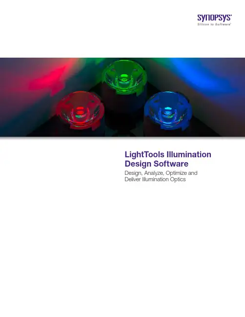
LightTools Illumination Design Software Design, Analyze, Optimize andDeliver Illumination Optics2Design HighlightsThe Complete Design Solution for Illumination ApplicationsDesign accurate, cost-effective illumination optics with LightTools ® software. Its unique design and analysis capabilities, combined with ease of use, support for rapid design iterations and automatic system optimization help to ensure the delivery of illumination designs according to specifications and schedule.Smart system modeling with full optical accuracy and precision — Createdesigns easily with 3D solids that can be inserted into the model at any size, in any location and at any orientation. Geometry is always editable using Boolean andtrimming operations that retain the optical accuracy of surface shape, position and intersection for all calculations.Rapid evaluation of optical behavior during design iterations — With point-and-shoot ray tracing, gain an instant understanding of the system’s optical behavior by graphically starting and aiming rays from any point in the model. Rays are displayed visually and updated automatically as the model is changed and they can be moved and rotated interactively to study the behavior of a model.Quick convergence on the design that best meets your goals — Improve system performance automatically with the most effective illumination optimization algorithms available. LightTools’ fully integrated optimization capabilitiescombine design and analysis features to allow you to optimize any aspect of your system to meet performance goals. For example, optimize a system to match a target illumination distribution whilesimultaneously maximizing total power.Figure 1: LightTools’ smart modeling capabilities make it easy to quickly build complex illumination systems. Point-and-shoot ray tracing provides instantfeedback on system alignment.3Figure 5: Surgical lamp modeled in the LightTools Advanced Design Module.Robust modeling of complex su rfaces — Model complex optical surfaces with skinned solids, a highly versatile, fully optimizable class ofgeometrical objects whose size and shape are defined by multiple cross-sectionsalong their length. Apply textures — 2D, 3D and user defined — to any planar surface and vary the shape, size and spacing of texture elements as needed. Use theExceptional Software SupportWhen you use LightTools, you can expect to receive the most comprehensive software support in the industry to ensure that you are productive throughout your illumination design projects.``Expert technical support staff comprised of degreed optical engineering professionals``Dedicated customer website includes FAQs, macros, example models, tips and more ``Comprehensive documentation ``Onsite and offsite software training``Regular program updates with customer-requested enhancementsAdvanced Design Module to quicklymodel freeform optics and produce optical systems that have superior light control, increased energy efficiency and innovative design forms.Efficient model parameter management — Use parametriccontrols to establish links among optical system parameters so that changing one parameter automatically updates all associated parameters. Design modifications correctly propagatethroughout the system, maintaining both the design intent and the physical realism of the model.Ease of use — Work faster with LightTools’ smart user interface. Hierarchical data structures, editable spreadsheets, tabbed dialog boxes, multiple design views and navigation windows support interactive geometry creation and modification. Reduced design time with libraries, example models and utilities — Jump start your design with LightTools’ robust set of libraries, including sources,materials, lenses and surface treatments. Example models demonstrate key LightTools features, such as modeling sources and defining surface properties.Custom solutions to automate tasks and leverage other tools — Have unlimited design flexibility with the LightTools COM interface. Automaterepetitive design tasks using Visual Basic ® macros. Incorporate LightTools functions into other COM-enabled applicationsFigure 2: LED collimator modeled and optimized with LightTools’ SOLIDWORKS Link Module. It was designed in SOLIDWORKS, linked to LightTools, and optimized to achieve collimated light. The top images, including intensity plot, show the starting design andthe bottom images the optimized solution.Phosphor Coatingsuch as Microsoft Excel ® or MATLAB ® to achieve an integrated, multi-application engineering environment.Seamless information sharing with CAD programs — Import and export CAD data using industry-standard formats. Associate LightTools entities with CAD files andupdate geometry with the click of a button. Link SOLIDWORKS models to LightTools and optimize your design. Group and simplify imported geometry and perform repairs to maintain CAD model integrity and improve ray trace speed.Figure 3: Spotlight model with curved cover lens. A series of toroidal lensletson its output face spread the light into anelliptical pattern.Figure 4: LightTools can easily handle complex LED packaging designrequirements. You can immerse elements in one another, in multiple levels — ideal for modeling the embedded phosphor and epoxy covering in an encapsulated LED.4Analysis HighlightsAnalysis Tools That Verify and Ensure Design PerformanceWith LightTools’ virtual prototyping capabilities, you can quickly analyze your system and perform tradeoff studies. Explore design alternatives,study light behavior and improve product quality by identifying and fixing potential problem areas early in the product development process.LightTools calculates all the photometric and radiometric quantities needed to perform a complete illumination analysis. Define any number of receivers on real or virtual surfaces in the model to collect ray trace results for illumination analysis. Calculate illuminance, luminance, luminous intensity (near and far field) and encircled energy (angular and spatial) at any receiver.Figure 6: LightTools’ full suite of analysis tools includes intensity, luminance,illuminance and color performance charts.5 Angular and spatial luminanceanalysis — Attach angular and spatialluminance meters to surface receivers toanalyze and display luminance. Move theluminance meter angle to see what thefabricated system’s performance will looklike at any viewing angle, in real time.Accurate predictions of colorimetricperformance — Obtain calculations ofCIE coordinates (1931 x-y or 1976 u’-v’)for receivers as well as the CorrelatedColor Temperature (CCT) as a functionof position or angle. Visualize true colorappearance of an illuminated surfaceusing the RGB plotting capability.Simulation of real-worldconditions — Include surface effects suchas polarization, scattering, reflection andrefraction (with Fresnel losses) and theperformance of thin film coatings. Includematerial effects such as dispersion,volumetric absorption, volume scatteringand color filtering.Flexible, efficient Monte Carlo raytracing — Perform an accurate illuminationanalysis with rapid and robust Monte Carlosimulations. Select forward or backwardray tracing to enhance simulation speedand accuracy. Filter data accordingto a variety of criteria to improve yourunderstanding of the results. Graphicallydisplay the paths of traced rays. Defineaim regions for sources and surfacescatterers to limit traced rays to importantareas of the model.Accelerated ray tracing — Select raytracing shortcuts to speed up simulations.With accelerated ray tracing, control thelevel of accuracy on selected surfaces toincrease ray trace speed by 4x to 60x ormore. Turn on probabilistic ray splitting toenable LightTools to intelligently choosewhich rays to trace and to ignore ray pathsthat carry little power.Visual design evaluation andcommu nication — Visualize illuminancein the 3D model to quickly understand thedistribution relative to model geometry.Generate photorealistic renderings toassess and demonstrate how yourillumination optics look and perform.Include lit appearance in photorealisticrenderings to show the luminance effectsof light sources contained in the model.Figure 7: CIE color difference analysiscalculates and optimizes system colorperformance. This is useful for producingan even color distribution.Figure 8: LightTools’ photorealisticrenderings can demonstrate theappearance of your optical systemduring design evaluations and productpresentations.Figure 9: Visualize illuminance in the 3Dmodel to quickly understand the shapeand orientation of the distribution acrossa receiver relative to model geometry.Figure 10: LightTools charting providesmany options to customize illuminationsimulation results to meet personal,company or industry standards.Customizable, interactivecharting — Display the output ofillumination calculations as line or rasterplots, scatter plots, contour plots, 3Dsurface plots and many more formats.Interactively rotate and zoom charts toview a specific region of data. Customizecharts to meet personal, company orindustry standards.Faster solutions with increasedcompu ter power — Speed up complexanalysis and optimization processes withLightTools’ multi-CPU support. LightToolsmakes full use of hardware configurationsinvolving multiple CPUs or singleCPUs with hyperthreading or multiplecore architecture.6ApplicationsSample Applications and Key FeaturesAcross a broad range of illumination applications, LightTools helps you get high-performance, cost-effective systems to market faster. Complete design and analysis features, combined with groundbreaking illumination optimization capabilities, allow you to achieve design solutions unachievable with any other software. View a gallery of LightTools applications at /lighttools/lighttools-application-gallery.html.LEDs, including LED dies, LED arrays and LED packaging ``LED utility to quickly build a complete model``Library of pre-defined LEDs ``Multiple immersion for modeling the embedded phosphor and epoxy covering in an encapsulated LED ``Fully optimizable skinned solids for creating efficient LED couplers ``User-defined materials to model phosphor-based white LEDs ``Advanced Design Module tools for fast, robust modeling of freeform optics used in LEDs and LED collimator lensesBacklit displays``2D and 3D textures, including multiple appliqués, dot patterns, fine groove structures and bump structures for solids and surfaces ``User-defined 3D texture shapes and patterns for designing and analyzing arrays of complex surface reliefs ``Backlight utility that automates system setup and facilitates rapid design studies``Backlight Pattern Optimization utility that designs and optimizes backlight extraction patternsDigital and overhead projectors ``Library of pre-defined LCD, DMD and LCoS projector models``Light source definition using existing ray data sources, including Radiant Source ™ Models``Built-in colorimetry analysis features to evaluate color quality and simulate display appearance ``Skinned solids to create complex mixing-rod shapes with minimal effort and optimization capabilities that automatically refine the design form``Backward ray tracing for rapid, high-accuracy spatial luminance calculationsFigure 12: Cutaway of an LED-driven backlight. The pattern of extracting textures has been optimized using LightTools’ Backlight Pattern Optimizer to give the uniform output shown (partially)on the right side of the model.Figure 11: This photorealistic rendering of a lit LED shows a level of source model detail that can be easily achieved inLightTools.7Lighting/luminaires``Photorealistic renderings to visualize both how a luminare is lit and how it lights a room``Reflector construction andautomatic pattern-generation tools ``User-defined 3D textures that efficiently model a variety of complex components, from pillow optics to light diffusers for fluorescent troffers ``True-color RGB output``Utility to read and convert IES-formatted angular intensity data files into LightTools angular apodization files``MacroFocal Reflector tool fordesigning multi-surface segmented reflectorsLightpipes``Interactive construction, parametric editing and automatic optimization of complex shapes``2D and 3D texture capabilities, where each solid or surface can have multiple appliqués, dotpatterns, fine groove structures or bump structures``Probabilistic ray splitting, Fresnel loss and mixed scatter to improve speed and accuracy of light pipe simulations``Volume scattering inside amaterial to simulate the diffusing characteristics of appliqués Stray light simulation ``Ray path analysis that visually identifies stray light issues and summarizes energy flux and total power``Point-and-shoot rays that illustrate potential ray path problems ``Receiver data filtering for multiple analyses from a single simulation``Importance sampling using aim areas for efficient analysis of stray light in systems``Ghost image analyzer utility ``Vehicle interior lighting and displays ``Library of pre-defined LED and filament sources``CAD import and export to leverage existing data``Photorealistic renderings of an optical system’s lit appearance ``Virtual luminance meters that can be graphically positioned at any location in the model space to measure spatial and angular luminance and evaluate display visibility and quality Vehicle interior lighting``Macro control of spline, sweep and patch surfaces``Far-field and surface receivers that collect light rays and successfully predict the luminous intensity output of lighting components ``Accelerated ray tracing of imported CAD geometrySolar collection and daylighting ``Skinned solids for classical and custom solar collection optics ``Solar utilities for modeling of solar collection systems``3D textures to model brightness-enhancing optics``Fluorescence to enhance light capture in solar concentrators ``Photorealistic renderings to show the effect of daylighting enhancementsMedical devices``Full suite of volumetric optical effects, including scatter,phosphorescence and absorption ``Ability to apply Henyey-Greenstein and Gegenbauer models to a material for tissue modeling ``Extensible BSDF surface scattering capabilitiesMachine vision and laser scanning components``GRIN material modeling and a full complement of geometric laser propagation capabilities ``Accurate geometric modeling of both illumination and detection optics across the electro-magnetic spectrum``Photorealistic renderings to evaluate illuminator and detection optics from the detector’s point of viewAerospace and defense/spaceborne systems``Stray light and off-axis rejection analysis, including aim areas and importance sampling ``Blackbody source spectrum ``CAD import for optical mounts and assembliesFigure 15: LightTools is useful for modeling the effect of solar radiation for daylighting and architectural applications.Figure 14: Automotive interior lightingmodeled in LightToolsFigure 13: LED street lamp modeled inLightTools08/15.CE.CS6211.Synopsys, Inc. • 690 East Middlefield Road • Mountain View, CA 94043 • ©2015 Synopsys, Inc. All rights reserved. Synopsys is a trademark of Synopsys, Inc. in the United States and other countries. A list of Synopsys trademarks is available at /copyright.html . All other names mentioned herein are trademarks or registered trademarks of their respective owners.Core ModuleThe LightTools Core Module provides graphical 3D solid modeling functionality and interactive optical ray tracing for creating and visualizing optical and opto-mechanical systems, including the capability to specify properties for materials and optical surfaces.Productivity-enhancing features include an intuitive user interface, libraries of task- and application-specific utilities and examplesystems, programming extensions for automating workflow and photorealistic renderings of mechanical models.All other LightTools modules are fully integrated with the Core Module.For more information about LightTools modules, visit/lighttools/lighttools-modules.html.Configure LightTools to Meet Your NeedsLightTools has multiple modules that can be licensed in various configurations to meet your specific application needs. The CoreModule is a prerequisite for all other modules, which include the Illumination Module, Optimization Module, Advanced Design Module, Advanced Physics Module, SOLIDWORKS Link Module, Data Exchange Modules and Imaging Path Module. These modules work together seamlessly to provide a complete design and analysis solution for illumination systems.。
lighttools半导体激光管光源摘要:1.半导体激光管光源的概述2.半导体激光管光源的特点3.半导体激光管光源的应用领域4.半导体激光管光源的发展前景正文:【半导体激光管光源的概述】半导体激光管光源是一种采用半导体材料制造的激光光源。
激光光源,作为一种高度聚焦的光源,其具备的优异性能使得其在众多领域都有广泛的应用。
半导体激光管光源具有体积小、光束质量好、寿命长等特点,因此在激光应用领域具有重要的地位。
【半导体激光管光源的特点】半导体激光管光源具有以下特点:首先,它的体积小,便于安装和携带。
其次,半导体激光管光源的光束质量好,能够提供高精度、高强度的光束。
再次,半导体激光管光源的寿命长,能够在恶劣环境下持续工作。
最后,半导体激光管光源的效率高,能够将大部分电能转化为光能。
【半导体激光管光源的应用领域】半导体激光管光源在许多领域都有应用,例如通信、医疗、激光显示、光存储、激光加工等。
在通信领域,半导体激光管光源被用于光纤通信,可以提供高速、大容量的数据传输。
在医疗领域,半导体激光管光源被用于激光治疗,可以提供高精度、低损伤的治疗效果。
在激光显示领域,半导体激光管光源被用于激光投影,可以提供高清晰、高亮度的投影效果。
在光存储领域,半导体激光管光源被用于激光读写,可以提供高速、大容量的数据存储。
在激光加工领域,半导体激光管光源被用于激光切割、激光打标等,可以提供高效率、高精度的加工效果。
【半导体激光管光源的发展前景】随着科技的发展,半导体激光管光源的发展前景广阔。
未来,半导体激光管光源将在更多领域得到应用,例如自动驾驶、机器人、无人机等。
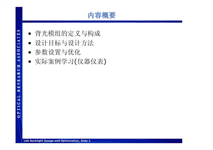
内容概要•背光模组的定义与构成•设计目标与设计方法•参数设置与优化•实际案例学习(仪器仪表)背光模组的定义•一般构成–导光板•通常其材料为塑料•注射成型或印刷式的网点(导光板下表面)–光源和反射罩•(典型光源CCFL and LED )–其他常用的光学元件扩散片(可提高均匀性)反射片•一些元件能否被使用取决于它的尺寸大小和成本以及其它要求Schematic of a typical backlight designLight source Light guideDiffuserReflectorAppliquéTransparency主要设计目标•在垂直光的传播方向上提升光的利用效率Light SourcePreferred direction of light extractionDirection of light propagationLight guideLight extraction from a light guide设计过程: 均匀性•光能量的传播是随导光板的长度变化的-出光的提取效率要随导光板的长度的增加而增加•改变光提取效率的方法:-改变网点密度,网点大小, 网点排布间距Distance from the sourceAvailable powerExtraction efficiencyUniform output背光网点设计•网点模型:印刷式的或注射成型的网点在背光设计中经常用到这两种网点来获得亮度均匀的背光•最佳的设计参数是优化后得到的网点密度分布Pattern Generator+CADIllumination SoftwareOutputOKUnacceptable优化过程通过不断反复调整网点参数进行优化,可以得到最终最佳的亮度与均匀性。
-可以通过做样品或软件模拟来完成光线追迹后输出模拟结果对比输出结果与初始要求网点参数设置计算新的网点更新模型完成OKNot OK网点参数的确定–为避免产生莫尔条纹,每个区域网点的密度是不一样的网点参数确定方法:–定义网点密度为二维网格值–定义网格值•网点的大小为变量•网点的数量和大小都为变量假设给定网点大小与形状通过计算在一个区域内变化网点的数量,得到想要的网点密度–网点密度的变化应该是缓慢而平滑的–人眼对突变是很敏感的,对渐变却不敏感变化网点数量的其他方法–分子动力学方法–多联骨牌法Mosaic Structure withObservableRectilinear Substructure Smooth Variation withObservableRectilinear SubstructureSmooth Variation withSinusoidal Shifts假设给定网点位置排布–经常用的排布一般为六角形通过计算在一个区域内变化网点的大小通过计算在一个区域内变化网点的大小,,得到想要的网点密度–出光的效率和网点排布的密度是成比例的Mosaic Structure using Hexagonal Pattern Smooth Variation using Hexagonal Pattern Smooth Variation using Rectilinear Pattern网点可以在位置的附近移动偏移网点可以在位置的附近移动偏移,,进行随机的变化, 但并不会重叠–也可以对网点的大小进行随机控制Dither X,Y=1,0Dither X,Y=0,1Dither X,Y=1,1Dither X,Y=0,0Dither X,Y=.2,.2Dither X,Y=.5,.5光线追迹与模拟评估此商业照明软件可以对背光进行设计模拟评估–运用蒙特卡罗随机光线追迹的方法来进行光度计算和模拟–模拟结果的精确度取决于光线追迹的数量和分辨率的高低高分辨率低精度低分辨率高精度高分辨率高精度--更多的光线--模拟评估可以使用优化函数进行模拟可以使用优化函数进行模拟,,比较输出结果与要求比较输出结果与要求,,进行评估-可使用优化函数限定统计噪声的最小值•当达到设计目标时可以中止优化函数•可增加光线的数目MF = ∑W i 2(V i -T i )2W i = Weight of i th MF item V i = Current Value of i th MF item T i = Target of i thMF itemLuminancewith 10,000 RaysLuminancewith1,000,000 RaysMF = ∑W i 2(V i + ∈i -T i )2MF = ∑W i 2(V i -T i )2 +Noise网点优化•BPO 通过改变网点的间距和大小来达到设计的要求•网点优化可以是2维的平面网点也可以是3维的网点•我们可以定义个接收面来接收并计算背光板表面的亮度和照度BPO 自动优化网点的过程•BPO 提供有效的优化网点的过程方法案例1: 印刷式导光板的网点优化在开始的时候使用均匀的印刷式网点进行优化得到合理的网点参数Small Source(e.g., LED)2D Display案例2: 注射成型网点的优化–网点大小相同,对排布的位置做优化处理来提高光的利用效率–这个例子是使用注射成型的网点进行优化LEDStartFinalTexture Density Output案例3: 两个LED, 非对称排布•使用注射成型的网点排布•两个LED–LED 采用非对称排布LEDsStartFinalTexture Density Output案例4: 两个LED, 对称排布•使用注射成型的网点排布•两个LED–LED 采用对称排布LEDsStartFinalTexture Density OutputSetupBitmap AppliquéSide ViewTop ViewLEDTextureAcrylic Light PipeBlue Filteron kph Appliqué•如下位图是作为优化的目标illuminance inthe blackregionsOptimization Results15 minutes2.33Ghz processor100,000 rays/iteration Iteration 1Iteration 2Iteration 3Iteration 4Iteration 5Iteration 6•模拟结果Illuminance Chart (1M rays) PhotoRealistic Rendering (100M rays)亮点边缘照明不足•需要新的目标区域设定全覆盖整个面积原有仪表盘结构新的仪表盘结构•最后的结果Photorealistic Rendering (100M rays)结论•网点的优化和模型设置及参数类型选择有紧密联系•介绍了用LightTools 进行设计和分析的一个汽车仪表盘背光的例子。
lighttools半导体激光管光源【最新版】目录1.半导体激光管光源简介2.半导体激光管光源的工作原理3.半导体激光管光源的种类和应用4.半导体激光管光源的优势和未来发展正文【半导体激光管光源简介】半导体激光管光源是一种采用半导体材料作为激光介质的激光光源。
半导体激光管(LD,Laser Diode)是一种能够发射激光的半导体器件,具有体积小、效率高、寿命长、光束质量好等优点,广泛应用于光通信、光存储、激光显示、激光测量、生物医学等领域。
【半导体激光管光源的工作原理】半导体激光管光源的工作原理是利用半导体材料的激光器结构,在特定的电压、电流和温度条件下,使半导体材料产生激发态电子和空穴,并通过光学谐振腔实现光放大和相干输出。
半导体激光管光源的发射波长与半导体材料的能带结构有关,不同材料的激光管可以实现不同波长的激光输出。
【半导体激光管光源的种类和应用】1.种类:根据半导体材料的不同,半导体激光管光源可分为不同类型,如砷化镓(GaAs)激光管、氮化镓(GaN)激光管等。
此外,还可以根据激光波长、输出功率、光束质量等参数进行分类。
2.应用:半导体激光管光源广泛应用于光通信、光存储、激光显示、激光测量、生物医学等领域。
例如,在光通信中,半导体激光管作为光发送端和接收端的光源,实现光信号的传输;在激光测量中,半导体激光管作为测量距离、速度、角度等的精确光源;在生物医学中,半导体激光管可以应用于激光治疗、激光诊断等。
【半导体激光管光源的优势和未来发展】1.优势:半导体激光管光源具有体积小、效率高、寿命长、光束质量好等优点,满足了各种应用场景的需求。
2.未来发展:随着科技的不断进步,半导体激光管光源在光通信、光存储、激光显示等领域的应用将更加广泛。
同时,新型半导体材料的研究与开发,如氮化镓、氮化铟等,将为半导体激光管光源提供更多的发展空间。
lighttools半导体激光管光源LightTools是一种先进的光学设计软件,它被广泛应用于半导体激光管光源的设计和优化。
半导体激光管光源是一种重要的光学器件,它能够产生高亮度、高能量的激光光束,被广泛应用于医疗、通信、材料加工等领域。
在半导体激光管光源的设计过程中,光学设计师需要考虑多个因素,如光束质量、功率稳定性、波长选择等。
而LightTools作为一款功能强大的光学设计软件,能够帮助设计师快速、准确地完成这些任务。
首先,LightTools提供了丰富的光学元件库,包括透镜、反射镜、光纤等。
设计师可以根据实际需求选择合适的元件,并进行组合和调整,以实现所需的光学效果。
此外,LightTools还支持自定义元件,设计师可以根据需要添加新的元件,以满足特定的设计要求。
其次,LightTools具有强大的光线追迹功能。
设计师可以通过设置光源的位置、方向和光束参数等,模拟光线在光学系统中的传播过程。
通过光线追迹,设计师可以分析光束的质量、聚焦性能等,优化光学系统的设计。
此外,LightTools还支持非顺序光线追迹,可以模拟光线在复杂光学系统中的传播过程,提高设计的准确性。
另外,LightTools还具有强大的优化功能。
设计师可以通过设置优化目标和约束条件,自动调整光学系统的参数,以达到最佳的设计效果。
优化功能可以大大提高设计的效率和准确性,帮助设计师快速找到最优解。
除了上述功能,LightTools还具有直观的用户界面和友好的操作方式,使得设计师可以轻松上手并快速完成设计任务。
同时,LightTools还支持与其他软件的数据交换,方便设计师与团队成员之间的合作和沟通。
总之,LightTools是一款功能强大的光学设计软件,对于半导体激光管光源的设计和优化具有重要的意义。
它提供了丰富的光学元件库、强大的光线追迹功能和优化功能,帮助设计师快速、准确地完成设计任务。
通过使用LightTools,设计师可以提高设计的效率和准确性,为半导体激光管光源的应用提供更好的解决方案。

运用LightTools设计背光显示2003年6月第一节背光设计简介本节介绍了如何运用LightTools来定义基本的背光。
本文供LightTools的初学用户使用,所以运用了很多相关的简单的例子并且包括产品的基本特性。
LightTools的高级用户可以跳过前半部分,直接到41页“高级背光设计”。
本节主要内容如下:·先决条件·什么是背光·普通光线输出技术·运用LightTools的计算机辅助设计·设置模拟·分析照明数据·更多照明数据导出先决条件要完成第一节中的练习,你首先得正确安装:·LightTools3.3版(或更高版本)。
·LightTools的系统(.lts)和库(.ent)文件确定可用,从光学研究协会网址上下载。
下载这些文件,首先在你的浏览器中输入:/LTFiles。
在“Designing Backlight Displays in LightTools”的栏目下点击BacklightFiles.zip。
把文件保存到硬盘然后把压缩文件解压到一个目录下(比如:C:\LTUser)。
什么是背光背光是指用于电子元件中的有一个要求背后出光的平面,其中可以包括小到PDA大到电视屏的电子设备。
典型的背光包括光源,导光板或者是所谓的light pipe。
光源一般置于导光板的一侧,以减小导光板的厚度。
侧光一般使用总的内反射来沿着演示器的长度方向来传播光,下边图表中所示就是典型的背光设计。
主要的要求就是均衡的光通过LCD的表面,而且光通量足够高,以便和日光环境有很好的对比度(这样你就可以在一台小型电脑或者掌上电子元件上边看见显示,比如,在室光条件下)。
如图2,设计的challenge就是使输出光方向于光传播方向,LCD平面刚刚好在导光板上方。
普通光输出技术从导光板以垂直于光传播方向输出光有好几种技术手段。
最普通的就是Printed light extraction和molded light extraction。
背光显示的光学设计工具LightTools 背光显示的光学设计工具LightTools 导言背光应用于小型轻便要求从背后照明的平板液晶显示器LCD等电子设备包括小到如手掌大小的手持设备大到大屏幕电视机。
背光设计的目标包括低功耗超薄高亮度亮度均匀大面积不同宽窄的视角控制。
为了实现这些挑战性的设计目标并控制成本和快速实现必须使用电脑辅助光学设计工具进行设计。
本文介绍了美国ORA公司的LightTools光学设计和分析软件的特性可用于开发当今最先进的背光设计应用。
用于背光的光学设计和分析工具背光照明系统需要将来自一个或多个光源的光进行某种转换然后在一个区域或一个立体角里产生需要的配光分布。
照明设计软件必须能够几何建模对不同类型的光源和转换单元设定光学特性参数而且必须能够使用光学追迹的方法来评价光线通过模型的路径并计算最后的光分布。
光分布采用蒙特卡罗模拟来计算特定区域和/或角度的照度亮度或发光强度。
光线从光源以随机的位置和角度发出通过光学系统追迹并在接收面上接收。
照度可以从表面接收器计算出来强度可以从远场接收器获得。
通过在接收器表面定义亮度计可以计算出亮度随空间和角度的分布。
在某些情况下分析显示器的色度可能是很重要的。
指定光源如发光二极管的光谱能量分布输出CIE 坐标值以及相关色温CCT量化显示器的色度在显示器上生成RGB真实光线渲染的图形。
这些分析在LightTools软件中都可以做到。
背光显示器的特点对照明分析软件有特别的要求。
正如将要说明的背光发出的光线取决于印刷点的分布密度或者微结构的分布模式。
对特定的微结构阵列的建模如果直接使用CAD模型可能会导致非常大的模型尺寸。
LightTools软件提供三维纹理阵列定义的功能能够进行准确的光线追迹和渲染由于没有使用直接构建的几何模型所以模型的体积更小光线追迹更快。
背光分析的另一个方面包括光线在导光板表面的分光和散射。
由于使用蒙特卡洛方法仿真照明效果有可能必须使用大量光线追迹以获得足够精度的设计。
先搞个序言天气冷大家多穿点衣服。
今年气候比较异常,感冒病毒变种显著增多。
千万不要在这个时候感冒,否则,你可能会是下一种猪流感的创始人。
如果别人家破人亡了,你要记得,那是你干的。
关于背光源信息显示如今这个社会有很多种信息显示技术,其中一些被用于照明显示。
我们今天所广泛使用的平板显示是基于LCD显示技术的,它通常都需要一个叫做背光源的照明系统。
这一章我们将通过一个简单的例子来介绍背光源设计,这个过程中可能会占用一部分内存。
一个背光源系统的大体结构如下图所示:·Light source(光源)。
正如这篇文章中的例子里,光源通常都是一个带有反射镜的冷阴极射线管(CCFL)。
而对于小型的显示器则一般使用一个到多个LED。
·Rectangular light guide(矩形导光板)。
它通常被人们叫做导光管,用来传输从边缘光源发出的用于照明液晶板的光线。
·Additional layers(增光板)。
许多背光系统利用显示器前面的散射或者增光装置(BEF)来适当的改变光照的均匀性和角度。
这个设计的重点在于把光线传输到垂直于原来的传播方向,这样就可以更好的为导光板上面的LCD液晶板提供照明。
这里有许多种传输方式,其中一些将会在backlight tutorial(背光指南)中描述和示范。
其中最主要的两种方式是印刷式输出(paint dots)和模型化输出(3D texture)。
不过这两种输出方式都依赖于lighttools中的property zone。
设计一个数字图像显示器在这篇文章的例子里,我们假定一个廉价的数字图像显示设备。
它由一个照明范围为3.5×5 inch(88.9×127mm)组成,附带一个存储记忆卡槽,这样你可以利用它来显示存储在一个数码相机里或个人电脑里的数字照片。
对于这些图片,控制操作等等,它具有充分的处理能力。
这个例子里不打算介绍这个设备里的包装,电源,处理器等器件,只是尽量简洁的描述显示器。
lighttools半导体激光管光源【原创实用版】目录1.引言:半导体激光管光源的概述2.半导体激光管光源的工作原理3.半导体激光管光源的特点与优势4.半导体激光管光源的应用领域5.结论:半导体激光管光源的发展前景正文【引言】半导体激光管光源是一种采用半导体材料作为工作物质的发光器件,具有体积小、光束质量高、寿命长等特点。
近年来,随着半导体技术的不断发展,半导体激光管光源已广泛应用于各种领域,如通信、照明、医疗等。
本文将对半导体激光管光源的工作原理、特点与优势以及应用领域进行介绍,并探讨其发展前景。
【半导体激光管光源的工作原理】半导体激光管光源的工作原理主要基于半导体材料的激光特性。
在半导体材料中,电子和空穴通过复合作用释放出能量,从而产生光子。
当半导体材料被激励,电子和空穴的浓度增加,导致更多的复合作用,进而产生更多光子。
这种光子发射现象称为激光。
半导体激光管光源通过这种原理产生高亮度、高单色性、高方向性的光束。
【半导体激光管光源的特点与优势】半导体激光管光源具有以下特点与优势:1.体积小:半导体激光管光源采用半导体材料制作,具有较小的体积,便于集成和安装;2.光束质量高:半导体激光管光源发出的光束具有较高的单色性和方向性,适用于高精度的应用场合;3.寿命长:半导体激光管光源的寿命可以达到数万小时,具有较高的稳定性和可靠性;4.效率高:半导体激光管光源的电光转换效率较高,有利于节约能源;5.可调谐性:半导体激光管光源的工作波长可以通过改变半导体材料的组成和结构进行调节,满足不同应用场合的需求。
【半导体激光管光源的应用领域】半导体激光管光源已广泛应用于以下领域:1.通信:半导体激光管光源作为光纤通信的重要光源,可实现高速、远距离的数据传输;2.照明:半导体激光管光源具有高光效、高显色指数等特点,可用于照明领域,如室内照明、道路照明等;3.医疗:半导体激光管光源在医疗领域的应用包括激光治疗、激光手术等,具有创伤小、恢复快等优点;4.测量与检测:半导体激光管光源的高精度、高稳定性特点使其成为测量与检测领域的理想光源,如激光测距、激光雷达等。
lighttools text数据建立光源分布如何使用LightTools软件来建立光源分布。
LightTools是一款功能强大的光学仿真软件,可用于设计和分析各种光学系统。
在光学系统设计中,光源分布是一个重要的参数,它影响着整个系统的性能和效果。
下面将一步一步介绍如何在LightTools中建立光源分布。
第一步:导入模型和设置环境条件在LightTools中,首先我们需要导入光学系统的模型。
可以通过导入CAD文件或者使用LightTools内建的建模工具来创建模型。
导入模型后,我们还需要设置环境条件,包括折射率、光源的波长和功率等。
第二步:选择光源类型在LightTools中,有多种光源类型可供选择,包括点光源、球面光源、面光源等。
根据实际需求,选择合适的光源类型。
点光源适用于较小的光源,球面光源适用于较大的光源,而面光源则适用于均匀的光源。
第三步:设置光源参数根据所选择的光源类型,设置光源的参数。
光源参数包括光源的位置、发射角度、发光功率等。
通过调整这些参数,可以控制光源的位置和方向,进而影响光源的分布。
第四步:调整光源分布根据实际需求,可以通过调整光源的位置和参数来达到期望的光源分布。
LightTools提供了直观的图形界面,方便用户对光源进行调整。
可以通过拖动光源的位置、旋转光源的方向、调整光源的发射角度等方式来改变光源的分布效果。
第五步:分析光源分布在调整完光源分布之后,我们可以使用LightTools提供的分析工具来评估光源分布的效果。
例如,可以使用光强度分析工具来查看不同位置的光强度分布情况,可以使用光通量分析工具来计算不同方向上的光通量分布情况等。
通过这些分析,可以进一步优化光源分布,使其更加符合设计要求。
第六步:保存和导出结果在完成光源分布的设计之后,我们可以将结果保存起来,以备后续使用。
LightTools提供了多种保存和导出结果的方式,可以保存为LightTools的工程文件,也可以导出为其他格式的文件,如CAD文件、图片文件等。
LightTools设计实例--汽车仪表盘导光按钮设计LightTools自带增光片元件库和光源库,其增光片元件库包括3M公司所有的BEF和DBEF;其光源库包括4大LED公司(Agilent, Lumileds,Nichia,Osram)的近400种LED光源,对设计LED照明的LCDTV有极大的方便。
传统导光板的网点设计更是及其方便,既可以模拟二维印刷点排布,也可以模拟三维的微结构铺设,目前微结构网点包括五种形状:球、棱镜、金字塔、圆锥、圆柱,极大的提高设计者的工作效率。
Cybernet中国使用LightTools对汽车仪表盘导光按钮的设计如下:重点:采用两颗小功率LED,实现导光按钮上的三个字母均匀发光。
设计步骤1.LED光源模拟仿真2.导光按钮的几何建模3.几何模型的材料属性、光学属性设定4.受光分析面,亮度计的设置5.光线追迹,结果分析6.根据分析结果修改按钮的几何模型,重复光线追迹过程,直至模拟仿真结果达到系统设计要求。
(采用LT的优化模块,可代替繁琐的模型更改,缩短项目开发周期)针对LED光源仿真这里简单说明一下参数,光源模型中都有详尽的参数设定以下介绍主要的参数(根据模拟目的不同,需要的参数也不同)•光束(lm)或者是辐射功率(mW)•光谱特性•配光分布•空间強度分布根据波长范围进行光源定义•LightTools可以高效灵活的设定光源.•LightTools可以提出包含面,体积的面光源和体积光源的定做方案.•LightTools中Ray Data的设定,可以使用Radiant Imaging测定的光源.•以放射量或测光能量为单位可以在光源中定义全部光能量.•用户定义的Aim领域和Aim锥体可以引出最佳性能.•为了配合这个高效的功能,计划在光源中定义连续的光谱.LightTools在导光按钮的几何建模上更有强大的内置建模能力通过Solidworks Link模块 LightTools完全继承来自SolidWorks的特征树可为使用过Solidworks的工程师提供熟悉的设计环境。