Influence Alloy
- 格式:pdf
- 大小:55.75 KB
- 文档页数:8

物料科学Material Science物料科学定义Material Science Definition加工性能Machinability强度Strength抗腐蚀及耐用Corrosionresistance durability金属特性Special metallic features抗敏感及环境保护Allergic,recyclingenvironmental protection化学元素Chemical element元素的原子序数Atom of Elements原子及固体物质Atom and solid material原子的组成、大小、体积和单位图表The size,mass,charge of an atom,and is particles (Pronton,Nentron and Electron) 原子的组织图Atom Constitutes周期表Periodic Table原子键结Atom Bonding金属与合金Metal and Alloy铁及非铁金属FerrousNon Ferrous Metal金属的特性Features of Metal晶体结构Crystal Pattern晶体结构,定向格子及单位晶格Crystal structure,Space latticeUnit cellX线结晶分析法X – ray crystal analyics method金属结晶格子Metal space lattice格子常数Lattice constant米勒指数Mills Index金相及相律Metal Phase and Phase Rule固熔体Solid solution置换型固熔体Substitutional type solid solution插入型固熔体Interstital solid solution金属间化物Intermetallic compound金属变态Transformation变态点Transformation Point磁性变态Magnetic Transformation同素变态Allotropic Transformation合金平衡状态Thermal Equilibrium相律Phase Rule自由度Degree of freedom临界温度Critical temperture共晶Eutectic包晶温度Peritectic Temperature包晶反应Peritectic Reaction包晶合金Peritectic Alloy亚共晶体Hypoeutetic Alloy过共晶体Hyperectectic Alloy金属的相融、相融温度、晶体反应及合金在共晶合金、固熔孻共晶合金及偏晶反应的比较Equilibrium Comparision金属塑性Plastic Deformation滑动面Slip Plan畸变Distortion硬化Work Hardening退火Annealing回复柔软Crystal Recovery再结晶Recrystallization金属材料的性能及试验Propertiestesting of metal化学性能Chemical Properties物理性能Physical Properties颜色Colour磁性Magnetisum比电阻Specific resistivityspecific resistance比重Specific gravityspecific density比热Specific Heat热膨胀系数Coefficient of thermal expansion导热度Heat conductivity机械性能Mechanical properties屈服强度(降伏强度) (Y ield strangth)弹性限度、阳氏弹性系数及屈服点elastic limit,Y eungs module of elasticity to yield point 伸长度Elongation断面缩率Reduction of area金属材料的试验方法The Method of Metal inspection不破坏检验Non – destructive inspections渗透探伤法Penetrate inspection磁粉探伤法Magnetic particle inspection放射线探伤法Radiographic inspection超声波探伤法Ultrasonic inspection显微观察法Microscopic inspection破坏的检验Destructive Inspection冲击测试Impact Test疲劳测试Fatigue Test潜变测试Creep Test潜变强度Creeps Strength第壹潜变期Primary Creep第二潜变期Secondary Creep第三潜变期Tertiary Creep主要金属元素之物理性质Physical properties of major Metal Elements工业标准及规格–铁及非铁金属Industrial Standard – FerrousNon – ferrous Metal磁力Magnetic简介General软磁Soft Magnetic硬磁Hard Magnetic磁场Magnetic Field磁性感应Magnetic Induction透磁度Magnetic Permeability磁化率Magnetic Susceptibility (Xm)磁力(Magnetic Force)及磁场(Magnetic Field)是因物料里的电子(Electron)活动而产生抗磁体、顺磁体、铁磁体、反铁磁体及亚铁磁体Diamagnetism,Paramagnetic,Ferromagnetism,AntiferromagnetismFerrimagnetism 抗磁体Diamagnetism磁偶极子Dipole负磁力效应Negative effect顺磁体Paramagnetic正磁化率Positive magnetic susceptibility铁磁体Ferromagnetism转变元素Transition element交换能量Positive energy exchange外价电子Outer valence electrons化学结合Chemical bond自发上磁Spontaneous magnetization磁畴Magnetic domain相反旋Opposite span比较抗磁体、顺磁体及铁磁体Comparison of Diamagnetism,ParamagneticFerromagnetism反铁磁体Antiferromagnetism亚铁磁体Ferrimagnetism磁矩magnetic moment净磁矩Net magnetic moment钢铁的主要成份The major element of steel钢铁用"碳"之含量来分类Classification of Steel according to Carbon contents铁相Steel Phases钢铁的名称Name of steel纯铁体Ferrite渗碳体Cementitle奥氏体Austenite珠光体及共释钢Pearlite Eutectoid奥氏体碳钢Austenite Carbon Steel单相金属Single Phase Metal共释变态Eutectoid Transformation珠光体Pearlite亚铁释体HyppoEutectoid初释纯铁体Proentectoid ferrite过共释钢Hypeeutectoid珠光体Pearlite粗珠光体Coarse pearlite中珠光体Medium pearlite幼珠光体Fine pearlite磁性变态点Magnetic Transformation钢铁的制造Manufacturing of Steel连续铸造法Continuous casting process电炉Electric furnace均热炉Soaking pit全静钢Killed steel半静钢Semikilled steel沸腾钢(未净钢) Rimmed steel钢铁生产流程Steel Production Flow Chart钢材的熔铸、锻造、挤压及延轧The Casting,Fogging,Extrusion,RollingSteel 熔铸Casting锻造Fogging挤压Extrusion延轧Rolling冲剪Drawingstamping特殊钢Special Steel简介General特殊钢以原素分类Classification of Special Steel according to Element特殊钢以用途来分类Classification of Special Steel according to End Usage易车(快削)不锈钢Free Cutting Stainless Steel含铅易车钢Leaded Free Cutting Steel含硫易车钢Sulphuric Free Cutting Steel硬化性能Hardenability钢的脆性Brittleness of Steel低温脆性Cold brittleness回火脆性Temper brittleness日工标准下的特殊钢材Specail Steel according to JIS Standard铬钢–日工标准JIS G4104Chrome steel to JIS G4104铬钼钢钢材–日工标准G4105 62Chrome Molybdenum steel to JIS G4105镍铬–日工标准G4102 63Chrome Nickel steel to JIS G4102镍铬钼钢–日工标准G4103 64Nickel,ChromeMolybdenum Steel to JIS G4103高锰钢铸–日工标准High manganese steel to JIS standard片及板材Chapter FourStrip,SteelPlate冷辘低碳钢片(双单光片)(日工标准JIS G3141) 73 95Cold Rolled (Low carbon) Steel Strip (to JIS G 3141)简介General美材试标准的冷辘低碳钢片Cold Rolled Steel Strip American Standard – American Society for testing and materials (ASTM) 日工标准JIS G3141冷辘低碳钢片(双单光片)的编号浅释Decoding of cold rolled(Low carbon)steel strip JIS G3141材料的加工性能Drawing abillity硬度Hardness表面处理Surface finish冷辘钢捆片及张片制作流程图表Production flow chart cold rolled steel coil sheet冷辘钢捆片及张片的电镀和印刷方法Cold rolled steel coilsheet electroplatingpainting method冷辘(低碳)钢片的分类用、途、工业标准、品质、加热状态及硬度表End usages,industrial standard,quality,condition and hardness of cold rolled steel strip硬度及拉力HardnessTensile strength test拉伸测试(顺纹测试)Elongation test杯突测试(厚度: 0.4公厘至1.6公厘,准确至0.1公厘3个试片平均数)Erichsen test (Thickness: 0.4mm to 1.6mm,figure round up to 0.1mm)曲面(假曲率)Camber厚度及阔度公差Tolerance on ThicknessWidth平坦度(阔度大于500公厘,标准回火)Flatness (width500mm,temper: standard)弯度Camber冷辘钢片储存与处理提示General advice on handlingstorage of cold rolled steel coilsheet防止生锈Rust Protection生锈速度表Speed of rusting焊接Welding气焊Gas Welding埋弧焊Submergedarc Welding电阻焊Resistance Welding冷辘钢片(拉力: 3032公斤/平方米)在没有表面处理状态下的焊接状况Spot welding conditions for bared (free from paint,oxides etc) Cold rolled mild steel sheets(T/S:3032 Kgf/ μ m2)时间效应(老化)及拉伸应变AgingStretcher Strains日工标准(JIS G3141)冷辘钢片化学成份Chemical composition – cold rolled steel sheet to JIS G3141冷辘钢片的"理论重量"计算方程式Cold Rolled Steel Sheet – Theoretical mass日工标准(JIS G3141)冷辘钢片重量列表Mass of ColdRolled Steel Sheet to JIS G3141冷辘钢片订货需知Ordering of cold rolled steel strip/sheet其它日工标准冷轧钢片(用途及编号)JIS standardapplication of other cold Rolled Special Steel电镀锌钢片或电解钢片Electrogalvanized Steel Sheet/Electrolytic Zinc Coated Steel Sheet简介General电解/电镀锌大大增强钢片的防锈能力Galvanic Action improving WeatherCorrosion Resistance of the Base Steel Sheet上漆能力Paint Adhesion电镀锌钢片的焊接Welding of Electrogalvanized steel sheet点焊Spot welding滚焊Seam welding电镀锌(电解)钢片Electrogalvanized Steel Sheet生产流程Production Flow Chart常用的镀锌钢片(电解片)的基层金属、用途、日工标准、美材标准及一般厚度Base metal,application,JISASTM standard,and Normal thickness of galvanized steel sheet 锌镀层质量Zinc Coating Mass表面处理Surface Treatment冷轧钢片ColdRolled Steel Sheet/Strip热轧钢片HotRolled Sheet/Strip电解冷轧钢片厚度公差Thickness Tolerance of Electrolytic Coldrolled sheet热轧钢片厚度公差Thickness Tolerance of Hotrolled sheet冷轧或热轧钢片阔度公差Width Tolerance of Cold or Hotrolled sheet长度公差Length Tolerance理论质量Theoretical Mass锌镀层质量(两个相同锌镀层厚度)Mass Calculation of coating (For equal coating)/MM锌镀层质量(两个不同锌镀层厚度)Mass Calculation of coating (For differential coating)/MM镀锡薄铁片(白铁皮/马口铁) (日工标准JIS G3303)简介General镀锡薄铁片的构造Construction of Electrolytic Tinplate镀锡薄钢片(白铁皮/马日铁)制造过程Production Process of Electrolytic Tinplate锡层质量Mass of Tin Coating (JIS G3*******)两面均等锡层Both Side Equally Coated Mass两面不均等锡层Both Side Different Thickness Coated Mass级别、电镀方法、镀层质量及常用称号Grade,Plating type,Designation of Coating MassCommon Coating Mass镀层质量标记MarkingsDesignations of Differential Coatings硬度Hardness单相轧压镀锡薄铁片(白铁皮/马口铁)SingleReduced Tinplate双相辗压镀锡薄钢片(马口铁/白铁皮)DualReduction Tinplate钢的种类Type of Steel表面处理Surface Finish常用尺寸Commonly Used Size电器用硅[硅] 钢片Electrical Steel Sheet简介General软磁材料Soft Magnetic Material滞后回线Narrow Hystersis矫顽磁力Coercive Force硬磁材料Hard Magnetic Material最大能量积Maximum Energy Product硅含量对电器用的低碳钢片的最大好处The Advantage of Using Silicon low Carbon Steel晶粒取向(GrainOriented)及非晶粒取向(NonOriented)Grain OrientedNonOriented电器用硅[硅] 钢片的最终用途及规格End Usage and Designations of Electrical Steel Strip电器用的硅[硅] 钢片之分类Classification of Silicon Steel Sheet for Electrical Use电器用钢片的绝缘涂层Performance of Surface Insulation of Electrical Steel Sheets晶粒取向电器用硅钢片主要工业标准International Standard – GrainOriented Electrical Steel Silicon Steel Sheet for Electrical Use晶粒取向电器用硅钢片GrainOriented Electrical Steel晶粒取向,定取向芯钢片及高硼定取向芯钢片之磁力性能及夹层系数(日工标准及美材标准)Magnetic Properties and Lamination Factor of SIORIENTCORE SIORIENTCOREHI B Electrical Steel Strip (JIS and AISI Standard)退火Annealing电器用钢片用家需自行应力退火原因Annealing of the Electrical Steel Sheet退火时注意事项Annealing Precautionary碳污染Prevent Carbon Contamination热力应先从工件边缘透入Heat from the Laminated Stacks Edges提防过份氧化No Excessive Oxidation应力退火温度Stress –relieving Annealing Temperature晶粒取向电器用硅[硅] 钢片–高硼(HIB)定取向芯钢片及定取向芯钢片之机械性能及夹层系数Mechanical Properties and Lamination Factors of SIORIENTCOREHIB and SIORIENTCORE Grain Orient Electrical Steel Sheets晶粒取向电器用硅[硅] 钢;片–高硼低硫(LS)定取向钢片之磁力及电力性能Magnetic and Electrical Properties of SIORIENTCOREHIBLS晶粒取向电器用硅[硅] 钢片–高硼低硫(LS) 定取向钢片之机械性能及夹层系数Mechanical Properties and Lamination Factors of SIORIENTCOREHIBLS晶粒取向电器用硅(硅)钢片高硼(HIB)定取向芯钢片,定取向芯钢片及高硼低硫(LS)定取向芯钢片之厚度及阔度公差Physical Tolerance of SIORIENTCOREHIB,SIORIENTCORE,SICOREHIBLS GrainOriented Electrical Steel Sheets晶粒取向电器用硅(硅)钢片–高硼(HIB)定取向芯钢片,定取向芯钢片及高硼低硫(LS)定取向芯钢片之标准尺寸及包装Standard Forms and Size of SIORIENTCOREHIB,SICORE,SIORIENTCOREHIBLS GrainOriented Electrical Steel Sheets绝缘表面Surface Insulation非晶粒取向电力用钢片的电力、磁力、机械性能及夹层系数Lamination Factors of Electrical,MagneticMechanical NonGrain Oriented Electrical电器及家电外壳用镀层冷辘[低碳] 钢片Coated (Low Carbon) Steel Sheets for Casing,ElectricalsHome Appliances镀铝硅钢片Aluminized Silicon Alloy Steel Sheet简介General镀铝硅合金钢片的特色Feature of Aluminized Silicon Alloy Steel Sheet用途End Usages抗化学品能力Chemical Resistance镀铝(硅)钢片–日工标准(JIS G3314)Hotaluminumcoated sheets and coils to JIS G 3314镀铝(硅)钢片–美材试标准(ASTM A46377)35.7 JIS G3314镀热浸铝片的机械性能Mechanical Properties of JIS G 3314 HotDip Aluminumcoated Sheets and Coils公差Size Tolerance镀铝(硅)钢片及其它种类钢片的抗腐蚀性能比较Comparsion of various resistance of aluminized steelother kinds of steel镀铝(硅)钢片生产流程Aluminum Steel Sheet,Production Flow Chart焊接能力Weldability镀铝钢片的焊接状态(比较冷辘钢片)Tips on welding of Aluminized sheet in comparasion with cold rolled steel strip钢板Steel Plate钢板用途分类及各国钢板的工业标准包括日工标准及美材试标准Type of steel PlateRelated JIS,ASTM and Other Major Industrial Standards钢板生产流程Production Flow Chart钢板订货需知Ordering of Steel Plate不锈钢Stainless Steel不锈钢的定义Definition of Stainless Steel不锈钢之分类,耐腐蚀性及耐热性Classification,Corrosion ResistantHeat Resistance of Stainless Steel铁铬系不锈钢片Chrome Stainless Steel马氏体不锈钢Martensite Stainless Steel低碳马氏体不锈钢Low Carbon Martensite Stainless Steel含铁体不锈钢Ferrite Stainless Steel镍铬系不锈钢Nickel Chrome Stainless Steel释出硬化不锈钢Precipitation Hardening Stainless Steel铁锰铝不锈钢Fe / Mn / Al / Stainless Steel不锈钢的磁性Magnetic PropertyStainless Steel不锈钢箔、卷片、片及板之厚度分类Classification of Foil,Strip,SheetPlate by Thickness表面保护胶纸Surface protection film不锈钢片材常用代号Designation of SUS Steel Special Use Stainless表面处理Surface finish薄卷片及薄片(0.3至2.9mm厚之片)机械性能Mechanical Properties of Thin Stainless Steel(Thickness from 0.3mm to 2.9mm) – strip/sheet不锈钢片机械性能(301,304,631,CSP)Mechanical Properties of Spring use Stainless Steel不锈钢–种类,工业标准,化学成份,特点及主要用途Stainless Steel – Type,Industrial Standard,Chemical Composition,Characteristicend usage of the most commonly used Stainless Steel不锈钢薄片用途例End Usage of Thinner Gauge不锈钢片、板用途例Examples of End Usages of Strip,SheetPlate不锈钢应力退火卷片常用规格名词图解General Specification of Tension Annealed Stainless Steel Strips耐热不锈钢HeatResistance Stainless Steel镍铬系耐热不锈钢特性、化学成份、及操作温度HeatResistance Stainless Steel铬系耐热钢Chrome Heat Resistance Steel镍铬耐热钢Ni Cr Heat Resistance Steel超耐热钢Special Heat Resistance Steel抗热超级合金Heat Resistance Super Alloy耐热不锈钢比重表Specific Gravity of Heat – resistance steel plates and sheets stainless steel不锈钢材及耐热钢材标准对照表Stainless and HeatResisting Steels发条片Power Spring Strip发条的分类及材料Power Spring Strip Classification and Materials上链发条Windup Spring倒后擦发条Pull Back Power Spring圆面("卜竹")发条Convex Spring Strip拉尺发条Measure Tape魔术手环Magic Tape魔术手环尺寸图Drawing of Magic Tap定型发条Constant Torque Spring定型发条及上炼发条的驱动力Spring Force of Constant Torque Spring and Wingup Spring定型发条的形状及翻动过程Shape and Spring Back of Constant Torque Spring定型发条驱动力公式及代号The Formula and Symbol of Constant Torque Spring边缘处理Edge Finish硬度Hardness高碳钢化学成份及用途High Carbon Tool Steel,Chemical Composition and Usage每公斤发条的长度简易公式The Length of 1 Kg of Spring Steel StripSK5AISI301 每公斤长的重量/公斤(阔100200公厘) Weight per one meter long (kg) (Width 100200mm)SK5AISI301 每公斤之长度(阔100200公厘) Length per one kg (Width 100200mm)SK5AISI301 每公尺长的重量/公斤(阔2.010公厘)Weight per one meter long (kg) (Width 2.010mm)SK5AISI301 每公斤之长度(阔2.010公厘)Length per one kg (Width 2.010mm)高碳钢片High Carbon Steel Strip分类Classification用组织结构分类Classification According to Grain Structure用含碳量分类–即低碳钢、中碳钢及高碳钢Classification According to Carbon Contains弹簧用碳钢片CarbonSteel Strip For Spring Use冷轧状态Cold Rolled Strip回火状态Annealed Strip淬火及回火状态HardenedTempered Strip/ Precision – Quenched Steel Strip 贝氏体钢片Bainite Steel Strip弹簧用碳钢片材之边缘处理Edge Finished淬火剂Quenching Media碳钢回火Tempering回火有低温回火及高温回火LowHigh Temperature Tempering高温回火High Temperature Tempering退火Annealing完全退火Full Annealing扩散退火Diffusion Annealing低温退火Low Temperature Annealing中途退火Process Annealing球化退火Spheroidizing Annealing光辉退火Bright Annealing淬火Quenching时间淬火Time Quenching奥氏铁孻回火Austempering马氏铁体淬火Marquenching高碳钢片用途End Usage of High Carbon Steel Strip冷轧高碳钢–日本工业标准ColdRolled (Special Steel) Carbon Steel Strip to JIS G3311 电镀金属钢片Plate Metal Strip简介General电镀金属捆片的优点Advantage of Using Plate Metal Strip金属捆片电镀层Plated Layer of Plated Metal Strip镀镍Nickel Plated镀铬Chrome Plated镀黄铜Brass Plated基层金属Base Metal of Plated Metal Strip低碳钢或铁基层金属IronLow Carbon as Base Metal不锈钢基层金属Stainless Steel as Base Metal铜基层金属Copper as Base Metal黄铜基层金属Brass as Base Metal轴承合金Bearing Alloy简介General轴承合金–日工标准JIS H 5401Bearing Alloy to JIS H 5401锡基、铅基及锌基轴承合金比较表Comparison of Tin base,Lead base and Zinc base alloy for Bearing purpose易溶合金Fusible Alloy焊接合金Soldering and Brazing Alloy软焊Soldering Alloy软焊合金–日本标准JIS H 4341Soldering Alloy to JIS H 4341硬焊Brazing Alloy其它焊接材料请参阅日工标准目录Other Soldering Material细线材、枝材、棒材Chapter Five Wire,RodBar线材/枝材材质分类及制成品Classification and End Products of Wire/Rod铁线(低碳钢线)日工标准JIS G 3532Low Carbon Steel Wires ( Iron Wire ) to JIS G 3532光线(低碳钢线),火线(退火低碳钢线),铅水线(镀锌低碳钢线)及制造钉用低碳钢线之代号、公差及备注Ordinary Low Carbon Steel Wire,Annealed Low Carbon Steel Wire,Galvanized low Carbon Steel WireLow Carbon Steel Wire for nail manufacturing classification,Symbol of Grade,Tolerance and Remarks.机械性能Mechanical Properites锌包层之重量,铜硫酸盐试验之酸洗次数及测试用卷筒直径Weight of ZincCoating,Number of Dippings in Cupric Sulphate Test and Diameters of Mandrel Used for Coiling Test冷冲及冷锻用碳钢线枝Carbon Steel Wire Rods for Cold HeadingCold Forging (to JIS G3507)级别,代号及化学成份Classification,Symbol of Grade and Chemical Composition直径公差,偏圆度及脱碳层的平均深度Diameter Tolerance,Ovality and A verage Decarburized Layer Depth冷拉钢枝材Cold Drawn Carbon Steel Shafting Bar枝材之美工标准,日工标准,用途及化学成份AISI,JIS End Usage and Chemical Composition of Cold Drawn Carbon Steel Shafting Bar冷拉钢板重量表Cold Drawn Steel Bar Weight Table高碳钢线枝High Carbon Steel Wire Rod (to JIS G3506)冷拉高碳钢线Hard Drawn High Carbon Steel Wire(to JIS G3521,ISO8458012)化学成份分析表Chemical Analysis of Wire Rod线径、公差及机械性能(日本工业标准G 3521)Mechanical Properties (JIS G 3521)琴线(日本标准G3522)Piano Wires ( to G3522)级别,代号,扭曲特性及可用之线材直径Classes,symbols,twisting characteristic and applied Wire Diameters直径,公差及拉力强度Diameter,Tolerance and Tensile Strength裂纹之容许深度及脱碳层Permissible depth of flaw and decarburized layer常用的弹簧不锈钢线编号,特性,表面处理及化学成份StainlessSpring Wire –National Standard number,Charateristic,Surface finishChemical composition弹簧不锈钢线,线径及拉力列表Stainless Spring Steel,Wire diameter and Tensile strength of Spring Wire处理及表面状况FinishSurface各种不锈钢线在不同处理拉力比较表Tensile Strength of various kinds of Stainless Steel Wire under Different Finish圆径及偏圆度之公差Tolerance of Wire DiametersOvality铬镍不锈钢及抗热钢弹簧线材–美国材验学会ASTM A313 – 1987Chromium – Nickel Stainless and Heatresisting Steel Spring Wire – ASTM A313 – 1987化学成份Chemical Composition机械性能Mechanical Properties305,316,321及347之拉力表Tensile Strength Requirements for Types 305,316,321 and 347A1S1302 贰级线材之拉力表Tensile Strength of A1S1302 Wire日本工业标准–不锈钢的化学成份(先数字后字母排列)JIS – Chemical Composition of Stainless Steel (in order of numberalphabet)美国工业标准–不锈钢及防热钢材的化学成份(先数字后字母排列)AISI – Chemical Composition of Stainless SteelHeatResistant Steel(in order of numberalphabet)易车碳钢Free Cutting Carbon Steels (to JIS G4804 )化学成份Chemical composition圆钢枝,方钢枝及六角钢枝之形状及尺寸之公差Tolerance on Shape and Dimensions for Round Steel Bar,Square Steel Bar,Hexagonal Steel Bar易车(快削)不锈钢Free Cutting Stainless Steel易车(快削)不锈钢种类Type of steel易车(快削)不锈钢拉力表Tensile Strength of Free Cutting Wires枝/棒无芯磨公差表(μ) (μ = 1/100 mm)Rod/Bar Centreless Grind Tolerance易车不锈钢及易车钢之不同尺寸及硬度比较Hardness of Different TypesSize of Free Cutting Steel扁线、半圆线及异形线Flat Wire,Half Round Wire,Shaped Wire and Precision Shaped Fine Wire加工方法Manufacturing Method应用材料Material Used特点Characteristic用途End Usages不锈钢扁线及半圆线常用材料Commonly used materials for Stainless Flat WireHalf Round Wire扁线公差Flat Wire Tolerance方线公差Square Wire Tolerance。
J OURNAL OF RARE EARTHS,Vol.28,No.1,Feb.2010,p.54F j y M y f S T y f B j (D 55)LUOG (@)DOI 6S ()65Influence of pr eparation method on performance of a metal suppor ted per ovskite catalyst for combustion of methaneZHAI Yanqing (翟彦青),XIONG Jieming (熊杰明),LI Cuiqing (李翠清),XU Xin (徐新),LUO Guohua (罗国华)(Department of Chemical Engineering,Beijing Institute of Petro-chemical Technology,B eijing 102617,China)Received 21March 2009;revis ed 1June 2009Abstract:A different method was employed for the preparation of a metal supported perovskite catalyst for the catalytic combustion of meth-ane.The prepared metallic catalysts were characterized by means of X-ray diffractometer (XRD),scanning electron microscopy (SEM),transmission electron microscopy (TEM),and also by ultrasonic and thermal shock tests and catalytic activity.It was found that the process factors during the preparation,e.g.the preparation of the catalyst precursor and the coating slurry,the calcination temperature,all had strong effects on the activity and stability of the coated catalyst.Based on the experimental results,it was proposed that the sample adopted spray-pyrolysis method showed better catalytic activity and adhesion stability than those adopted co-precipitation and sol-gel.The increasing calcinations temperature could enhance adhesion stability,but reduce catalytic activity.For the coated samples,XRD illuminated that the typical well-crystallized perovskite structure was formed on the metallic surface after calcined at 800 C.SEM and TEM micrographs of the samples showed obvious dissimilarity at morphology aspect by different preparation methods.The LaMnO 3catalyst on the support by the spray-pyrolysis method had a mass loss 26%after 30min ultrasonic treatment and 7%after 10times thermal shock.Keywords:methane combustion;metallic monolith;perovskite catalyst;preparation method;adhesion;catalytic activity;rare earthsNatural gas is cleaner fuel than coal and petroleum.How-ever,the temperature of the methane combustion flame is higher than 1300C,and thus leads to a large amount of ther-mal NO x emission and a substantial heat loss [1].The catalytic combustion of the methane is one of the most promising processes to produce environmentally clean energy [2].In view of a practical application,the monolithic struc-tured catalyst is the only possible configuration of the cata-lytic combustion catalyst.The monolith catalyst has a lower gas-dynamic resistance than granulated catalyst.In addition,in monolith catalyst the cross section of heat and mass flows are uniform and decrease the probability of the formation of “hot ”zones and improve the time-on stream behavior of the catalyst and process selectivity [3].Metallic monolith exhibits several advantages over ce-ramic monolith,e.g.,with a better thermal and mechanical shock resistance,a high thermal conductivity,thus delaying catalytic and structural thermal damage.Moreover,it can be made with thinner walls than its ceramic counterpart,thus possessing a higher contact surface area.However,some disadvantages may be attributed to a metallic monolith,such as the non-porous nature of the metal,and the mismatch in the thermal expansion between the support and the coating layer [4].FeCrAl alloy has been used as a support in catalytic combustion due to its outstanding resistance to a high tem-perature,up to 1200C in air.This behavior depends on the diffusion of Al towards the surface and its oxidation into a pro-tecting layer of α-alumina,thus preventing the metals fromfurther oxidation and undesired alloy degradation.The aluminalayer is also quite useful for catalyst layer anchoring purpose [5].Perovskite-type catalyst has attracted great attention for combustion application as alternative to the very active no-ble metal catalyst [6].Development of the perovskite-based structured catalysts appears to be a very promising strategy to cope with all of those applications of catalytic combustion,which does not require extremely high activity at low tem-perature,but can benefit from a more heat-resistant and du-rable catalyst [7].Despite a considerable number of papers dealing with perovskite in the oxidation reactions,a few pa-pers have focused on the preparation of perovskite-based monolithic catalyst using La stabilized γ-Al 2O 3[8],corun-dum [9],zirconia [10]substrates or directly extruding active honeycomb structure system [11].For the metallic support,Cerri and colleagues [12]have investigated the catalytic per-formance of catalytic burner by employing the combination of a FeCrAl alloy fiber and perovskite catalyst.They have developed and optimized the technology of spray-pyrolysis of perovskite catalyst on metal surface.This paper reported the results of a study on FeCrAlloy supported perovskite for catalytic combustion of methane.The influence of the preparation method and calcination temperature on phase composition,micrograph,catalytic ac-tivity and adhesive of catalyst layer was investigated.1Experimentalound at ion ite m:Pro ect supported b the inistr o c ience and echnol og o ei ing 2008100000142Corre sponding a uthor :uohua E-m ail :luoguohua :10.101/1002-072109000-8ZHAI Yanqing et al.,Influence of preparation method on performance of a metal supported perovskite catalyst for combustion (55)1.1Prepar ationThe FeCr alloy(0.1mm thick)was used as the support. The sheet was cleaned ultrasonically in acetone and de-ionized water,and then was calcined at900C for5h. The heating rate was5C/min.1.1.1Co-precipitation A mixed solution of La,Mn nitrates with a total concentration of around1mol/L was employed, and a mixed solution of(NH4)2CO3and NaOH was used as a precipitating agent.The precipitation was carried out at am-bient temperature with pH9–10,followed by aging for3h. The precursor material was filtrated,washed and dried at 120C,and finally was calcined at700C for3h.The obtained powder dispersed with10wt.%ethanol and acetylacetone in a mixed solution of1:1.The suspension was then subjected to ball milling for10h.The pretreated sup-port was dipped into the slurry for3min and withdrawn slowly to ensure uniformity.Afterwards,the material was dried at80C for10min and calcined at800C for1h.The dip-coating and calcination process was repeated three times. Finally,the material was calcined at800,900,and1000C for5h in air,respectively.1.1.2Sol-gel The preparation process was as follows:the mixture of La(NO3)36H2O,Mn(CH3COO)24H2O was mixed with30wt.%citric acid and40wt.%water.The ob-tained solution was slowly heated at80C,until generating little viscous liquid.The pretreated metallic support was immerged in the vis-cous liquid for3min and withdrawn slowly to ensure uni-formity,then dried at120C and calcined at800C for1h. The dip-coating and calcinations process was repeated sev-eral times in order to obtain suitable loading of the catalyst on the support.Finally the material was calcined at800,900, and1000C for5h,respectively.1.1.3Spray-pyrolysis The mixture solution was composed of La(NO3)36H2O and Mn(CH3COO)24H2O with a molar ratio of1:1,30wt.%of citric acid and40wt.%water.The resulting equivalent LaMnO3concentration was0.7mol/L. The pretreated metallic support was heated in an oven up to900C,quick immerged in above solution,taken out af-ter10s,then dried at120C and calcined at800C for1h. The above process was repeated several times.Finally the material was calcined at800,900,1000C for5h,respec-tively.1.2Charact erizationXRD patterns were collected by a Rigaku D/max2500 X-ray diffractometer using the Cu Kαradiation(λ=0.15418nm), tube voltage40kV,tube current100mA.The morphology of samples was observed by a Quanta 400scanning electron microscope(FEI Corporation).The textural features of catalyst powder were studied by TEM with a JEM-100CX II.T f y y yT,treated in an ultrasonic bath for0.5–30min.The mass loss was measured.The thermal shock test was carried out by heating the coated sheets to800C at a heating rate10 C/min,holding for20min at800C,and dropping them immediately into water at25 C.After dried at120C,the mass loss was measured.The process was repeated10times. The catalytic activity was measured with a conventional tubular reactor under atmospheric pressure.The metal sheets coated with catalyst were cut into pieces of0.2–0.3×2–3cm.A bundle of pieces containing around0.3g perovskite were retained in the quartz tube vertically.A gas mixture of1.5 vol.%CH4and98.5vol.%air was used as a feed at a space velocity of60000ml/(g h),calculated according to the mass of the catalyst layer.The composition of the product was analyzed by an on-line Angilent4890gas chromatography with a thermal conductivity detector.2Results and discussion2.1Effect of the support pre-treat mentPretreatment must be conducted on support’s surface,be-cause smooth metallic surface is difficult to adhere catalyst. It has been demonstrated that at temperatures higher than 900C the aluminum diffuses preferentially,compared with the other alloy components,from the bulk of the material to the surface where the compact alumina was formed[5].The advantage associated with the alumina film is its compati-bility with alumina-containing washcoat,which substantially eases application and ensures its adhesion to the support. Furthermore,the Al2O3film protects the core of support free of further oxidation.For above reason,900C is selected as pretreatment temperature for the metallic support.The alloy possesses an obvious metallic luster and a smooth surface before pre-treatment.The metallic luster disappears and its surface becomes coarse after the alloy has been calcined at900C.The XRD pattern demonstrates that α-Al2O3phase forms,as seen in Fig.1(5).Fig.2(a)shows the SEM micrographs of pre-treated support.It can be seen that a coarse and dense oxide layer is well anchored to the metal surface with a tight structure.A lot of alumina whisk-ers completely cover metal surface,which increases greatly the surface area of the metal support.2.2Loading of catalystThe influences of the preparation method and calcination temperature on the loading of catalyst are listed in Table1.It clearly shows that the preparation method intensively affects loading of catalyst.For sample prepared by co-precipitation method,the loading attains around3%after two coatings only,whereas similar loading is attained after five coatings for samples prepared by sol-gel and spray-pyrolysis method.The influence of calcination tem-ff,he adhesion o the catal st la er was measured b an ul-trasonic test and a thermal shock test.he coated sheets were immersed in petroleum ether inside a sealed beaker and then perature on loading is negligible.Compared these three di erent method the loading is the56JOURNAL OF RARE EARTHS,Vol.28,No.1,Feb.2010Table 1Preparation method and the weight gains after coatingand calcination of samplesSamplePreparation methodNumber of coating Calcination temperature/C Mass gain/%1Co-precipitation 2800 3.22Co-precipitation 2900 3.03Co-precipitation 21000 3.14Sol-gel 5800 3.05Sol-gel 5900 3.16Sol-gel 51000 2.97Spray-pyrolysis 5800 3.18Spray-pyrolysis 5900 3.19Spray-pyrolysis510002.9highest for co-precipitation method,whereas coating number is the least.For co-precipitation method,the possible reason is that catalyst with certain perovskite structure adheres to support ’s surface in the form of powder,therefore the sample possesses the highest loading.For the sample prepared by sol-gel and spray-pyrolysis method,the precursor salt ad-heres to support surface firstly,then perovskite structure forms on the support after dryness and calcination processes.A lot of water and gas are removed,therefore a part of mass loses.In addition,a part of products in a foamy and brittle state adhere to the support,the foamy products ought to knock for next coating,so repetitious coating is needed for definite loading of catalyst.2.3XRD of the sampleThe XRD patterns of three catalyst coatings in comparison with that of a metal support and a catalyst precursor are de-picted in Fig.1.It shows that the XRD pattern,relative to the powder,shows the presence of rather well crystallized rhombohedral perovskite phase only after calcined at 700 C.For the coated samples,the typical well-crystallized per-ovskite structure is formed on the metallic surface after cal-cined at 800C in despite of different precursor history [13].In the coated samples,weak peaks of Al 2O 3attributed to sup-port ’s surface are detected.No other products are detectable.2.4SEM and TEM micrographs of sam plesThe SEM micrographs of the sample surface by different preparation methods and calcined at 800C are shown in Fig.2.The three samples exhibit obvious dissimilarity at mor-phology aspect.The sample 1shows that the exiguous cata-lyst powder is so close to one another as to form layer.The powder has homogeneous distribution onto the surface of the sheet,without evident conglomeration of catalyst particles.Sample 4reveals that the catalyst possesses two different morphologies, e.g.powder and crystal block.Exiguous catalyst powder particles are so close to one another as to form compact and even layer on the surface of metal.The irregular and vermiform catalyst crystal blocks occupy the complanate powder catalyst surface and form a secondary layer.Sample 7emerges that bigger crystal block close to the support surface and randomized surface cracks exists in the catalyst layer.From SEM it can be seen that a little catalyst exfoliates for all samples.It is known that the thermal expansion coeffi-cients for the perovskite and metallic support are 12×10–6K –1and 16×10–6K –1,respectively [5].With the temperature increasing,thermal stress between support and catalyst be-comes greater,which introduces cracks of a catalytic layer and falling of a small quantity of the catalysts.From TEM micrograph (Fig.3)obvious different size and shape of particles can be seen.The catalyst comprises of round particles for sample 1,whereas it is hexagonal with different size for samples 4and 7.On the basis of extensive image analysis,the average particle size of the catalyst of sample 1is about 100nm,whereas that of the other two samples is about 200nm.2.5Adhesion of catalyst on the supportThe adhesion of catalyst on the support is the important per-formance for the monolith catalyst,whereas many researchersFig.1XRD patterns of samples(1)Metal support calcined at 900C;(2)Perovskite powder cal-cined at 700C;(3)Sample 1;(4)Sample 4;(5)Sample7F S M f ,()S ;()S ;()S ;()S ig.2E micrographs o support calcined at 900C and samples 14and 7a upport calcined at 900C b ample 1c ample 4d ample 7ZHAI Yanqing et al.,Influence of preparation method on performance of a metal supported perovskite catalyst for combustion …57Fig.3TEM image of powder scraped from coated samples prepared by different method(a)Sample 1;(b)Sample 4;(c)Sample 7neglected it.The adhesion of the catalyst on the support pre-pared by different methods and at calcination temperatures has been investigated with ultrasonic and thermal shock test.Similar methods were used by Zhao et al.[14]and Ismagilov et al.[15]Typical mass loss-time curves for all samples during the ultrasonic test are presented in Fig.4.It can be seen that the mass loss increases as the ultrasonic treating time prolongs.For all samples,the figure of trend line is similar in ultrasonic test.The adhesion decreases gradually for the samples prepared by spray-pyrolysis,sol-gel,and co-precipitation method at the same calcination temperature.For the same preparation method,higher tem-perature is beneficial to improving adhesion.The sample 9has the highest stability.The mass loss data for all samples during the thermal shock test are illustrated in Fig.5.The comparative positions of curves of the samples in Figs.4and 5are more similar.During the two different tests,sample 9possesses the highest stability,with a mass loss 26%after 30min ultrasonic treat-ment and 7%after 10times thermal shock,while sample 1possesses the least stable among the 9samples.It can be found that the preparation method and calcina-tion temperature intensively affect the adhesion of catalyst on the support.The mass-loss is the least for the monolith prepared by spray-pyrolysis,due to the in situ pyrolysis oc-curring on the hot panel surface,in which catalyst crystalli-zation occurs leading to a fairly uniform load of catalyst,rather well anchors to the support.Besides abovereasons,F Wf Fig.5Mass loss-number curves ofthermocycletreating of samplesthe catalyst layer with a great deal of gaps can availably prevent the catalyst from falling off during ultrasonic test,because the catalyst falls off as tiny crystal block form with-out a larger piece of catalyst.For co-precipitation method,the catalyst composes integrate coating layer without crack,the catalyst breaks off with a large piece when the sample takes a beating,so mass loss is the most.2.6Catalyt ic activityThe activities for methane combustion reaction of all sam-ples are illustrated in Fig.6.The preparation method and calcinations temperature of samples have obvious effect on the activity.At the same calcination temperature,the cata-lytic activity of the sample prepared by spray-pyrolysis method is the highest with the light-off temperature (denoted 10%conversion)close to 500C,whereas the sample using sol-gel method presents the lowest catalytic activity,with light-off temperature approaching 600 C.The crystalline phase of the sample prepared by spray-pyrolysis method is formed completely,which is in favor of combustion of methane.The activity sequence does not show any relevance to the loading of the active layer.For a specific preparation method,catalytic activity obviously decreases with the in-crease of calcination temperature.3y ,y y ,ig.4eigh t lo ss-time curves du ring u ltrason ic treatment o samplesConclusionsAn active and stable methane combustion composite cata-l st based on a perovskite used as the catal tic la er and a58JOURNAL OF RARE EARTHS,Vol.28,No.1,Feb.2010Fig.6Catalytic activity of samplesFeCr alloy,used as the support was designed.The influence of the three different preparation techniques on the perform-ance of sample was studied.(1)FeCr alloy calcined at900C formed compact and coarse alumina layer,which was benignant for adhesion. (2)All the three technologies(spray-pyrolysis,co-pre-cipitation and sol-gel)were capable of making metallic monolith,which based deposition of LaMnO3catalyst on the support.(3)The preparation method had obvious effect on the ex-terior micrograph,adhesion,and catalytic activity of mono-lith.As a whole,the spray-pyrolysis technology was a prom-ising method for preparing metallic monolith.A higher tem-perature was propitious to increase adhesion,but decreased catalytic activity of monolith.References:[1]Thevenin P O,Menon P G,J r s S G.Catalytic processes toconvert methane:Partial or total oxidation,Part II Catalytic to-tal oxidation of methane.Cattech,2003,7:10.[2]Choudhary T V,Banerjee S,Choudhary V R.Catalysts forcombustion of methane and lower alkanes.A ppl.Catal.,A, 2002,234:1.[3]Norton D G,W etzel E D,Vlachos D G.Fabrication of sin-gle-channel catalytic microburners:effect of confinement on the oxidation of hydrogen/air mixtures.Ind.Eng.Chem.Res., 2004,43:4833.[4]Ferrandon M,Berg M,Bjornbom E.Thermal stability ofmetal-supported catalysts for reduction of cold-start emission in a wood-fired domestic boiler.Catal.T oday,1999,53:647.[5]Badini C,Laurella F.Oxidation of FeCrAl alloy:influence oftemperature and atmosphere on scale growth rate and mecha-nism.Surf.Coat.T echnol.,2001,135:291.[6]Barbero B P,Gamboa J A,Cadu s L E.Synthesis and charac-terization of La1–x Ca x FeO3perovskite-type oxide catalysts for total oxidation of volatile organic compounds.A ppl.Catal.,B, 2006,65:21.[7]Zhao Xin,Yang Qiuhua,Cui Jinjin.XPS study of surface ab-sorbed oxygen of ABO3mixed oxides.Journal ofRare Earths, 2008,26:511.[8]Cimino S,Lisi L,Pirone R,Russo G,Turco M.Methane com-bustion on perovskites-based structured catalysts.Catal.T oday, 2000,59:19.[9]Lyubov A Isupova,Galina M Alikina,Sergei V Tsybulya,Alek-sei N Salanov,Nataliya N Boldyreva,Elena S Rusina,IzabellaA Ovsyannikova,Vladimir A Rogov,Rimma V Bunina,Vladislav A Sadykov.Honeycomb-supported perovskite cata-lysts for high-temperature processes.Catal.T oday,2002,75: 305.[10]Cimino S,Pirone R,Lisi L.Zirconia supported LaMnO3mono-liths for the catalytic combustion of methane.A ppl.Catal.,B, 2002,35:243.[11]Fabbrini L,Rossetti I,Forni L.Effect of primer on honey-comb-supported La0.9Ce0.1CoO3±δperovskite for methane catalytic flameless combustion.A ppl.Catal.,B,2003,44:107.[12]Cerri I,Saracco G,SpecchiaV,Trimis D.Improved-performanceknitted fibre mats as supports for pre-mixed natural gas cata-lytic combustion.Chem.Eng.J.,2001,82:73.[13]Steenwinkel Y Z,Beckers J,Bliek A.Surface properties andcatalytic performance in CO oxidation of cerium substituted lanthanum-manganese oxides.A ppl.Catal.,A,2002,235:79.[14]Zhao S,Zhang J,Weng D,W u X.A method to form well-ad-heredγ-Al2O3layers on FeCrAl metallic supports.Surf.Coat.T echnol.,2003,167:97.[15]Ismagilov Z R,Pushkarev V V,Yu O.Podyacheva N A.Kory-abkina,V eringa H.A catalytic heat-exchanging tubular reactor for combining of high temperature exothermic and endother-mic reactions.Chem.Eng.J.,2001,82:355.。
JMEPEG(2001)10:596–601᭧ASM International Evaluation of an Al-Zn-Mg-Li Alloy/Potential Candidateas Al-Sacrificial AnodeS.Valdez,J.Genesca,B.Mena,and J.A.Juarez-Islas(Submitted22March2000;in revised form5June2000)This paper forms part of an overall effort to develop Al-sacrificial In/Hg free anodes;our research hasbeen directed toward developing Al alloys appropriate for cathodic protection.The Al-Zn-Mg system hasbeen particularly selected due to the presence of precipitates in the␣-Al matrix,which are capable ofbreaking down passive films while presenting good electrochemical efficiencies.At the same time,the effectof Li additions on superficial activation of the anode by means of precipitation of AlLi-type compoundswas examined.The microstructure was characterized in the as-cast and as-aged ingots,showing the presenceof␣-Al dendrites as well as eutectic of Al2Mg3Zn3and precipitates of Mg7Zn3in interdendritic regions.Electron microscopic observations performed on specimens with and without heat treatments showed inthe␣-Al matrix the presence of a uniform distribution of precipitates of(-Al2Zn3Mg3,Mg7Zn3,and␦-AlLi type.The electrochemical behavior of the alloy was investigated in a3%NaCl solution simulatingseawater at room temperature.After evaluation of the electrochemical efficiency,values up to67%wereobtained.The relationship between microstructure and electrochemical efficiency is discussed in this workand suggestions of future research are given in order to improve the electrochemical behavior of Al anodesin the field.to environmental protection.Particularly,the use of In alone Keywords Al-sacrificial anodes,electrochemical efficiency,or coupled with Hg in Al alloys during dissolution results in microstructure,precipitatessea life pollution and gives rise to great environmental issues.In order to avoid sea life pollution due to elements such as Hg 1.Introductionand In,and at the same time provide an Al alloy adequate forcathodic protection application,the Al-Zn-Mg system has been Presently,the most commonly used sacrificial metals for investigated in terms of distribution of intermetallics in the␣-cathodic protection systems are alloys of Mg,Zn,and Al.Al matrix capable of breaking down passive films as well The Al anodes are keenly related to alloy chemistry and to as presenting good electrochemical efficiencies.[3]Regarding environmental application.Aluminum has attained considerable electrochemical efficiency or anode current capacity,this should merit as the basis for a galvanic anode mainly due to its lowbe expressed in A-h/kg(where A-h is ampere-hour)and density,large electrochemical equivalent,availability,and rea-represents a figure of the effectiveness of the anode alloy.The sonable cost.The low electrode potentials of Al anodes areelectrochemical capacity is often expressed as percent of readily adaptable to a variety of saline environments such asefficiency.seawater,marine muds,and brackish waters.Unalloyed AlFor instance,it has been reported,[4]in the as-cast condition, adopts a relatively noble solution potential in saline media asthe existence of a microstructure consisting of␣-Al solid solu-a result of its protective oxide film.The oxide is the cause oftion with precipitation of thephase and a eutectic consisting rapid polarization when aluminum is placed under a corrosionof a fine dispersion of the␣ϩsegregated at grain boundaries. load in a cathodic protection circuit.Nevertheless,the successFurther dispersion of thephase in the matrix has been of the Al anode depends upon the alloying of certain metalsincreased by means of thermal treatments applied to as-cast whose surface role is to ultimately prevent the formation of aingots,by taking advantage of the fast kinetic reactions taking continuous,adherent,and protective oxide film on the alloy,place in solid state at400ЊC,giving as a result Al anodes with thus permitting continuous galvanic activity of the aluminum.electrochemical efficiencies up to78%.[5]Research carried out toward the development of Al alloys appro-This research has as its main scope to identify the possibility priate for cathodic protection has considered the influence ofalloying elements such as Zn,Ti,Hg,and In.[1,2]The use of each of the substitution of Al-Zn-In and Al-Zn-In-Hg sacrificial of those elements has shown an improvement of Al activation in anodes,by alloys of the Al-Zn-Mg type,in order to avoid sea neutral chloride media.However,the seemingly good results life pollution without decreasing the current efficiency of the obtained in this field are in contrast with the increased sensitivity resulting anodes.The first part of this research was focused onthe identification and distribution of precipitates in the Al alloy,in order to achieve two targets:the first one is to obtain a good S.Valdez,B.Mena,and J.A.Juarez-Islas,Instituto de Investigaciones surface activation of the anode and the second to yield corrosion en Materiales-UNAM,Circuito Escolar S/N,Cd.Universitaria,04510,products similar to those found in seawater in order to avoid Mexico,D.F.Mexico;and J.Genesca,Fac.de Quimica,Depto depollution of sea life.As a first step,reference was made of Metalurgia-UNAM,Circuito Escolar S/N,Cd.Universitaria.Contacte-mail:julioalb@servidor.unam.mx.the work of Barbucci[5]producing Al-Zn-Mg alloys but withadditions of Li.The resulting microstructure was then character-ized,with particular attention paid to identification of precipi-tates in the␣-Al matrix and eutectics in interdendritic regions,in both as-cast ingot and aged samples.The research was alsodirected toward the effect of Li additions on superficial activa-tion of the anode by means of precipitation of the␦-AlLiintermetallic at grain boundaries and/or matrix,and by takingadvantage of the fact that the Zn decreases the solid solubilityof Li in the␣-Al phase.[6]2.Experimental ProcedureAn Al-5at.%Zn-5at.%Mg-0.1at.%Li alloy was preparedwith commercially available Al,Zn,and Mg with purities of99.98%.The Li was used as a wire of3.2mm in diameter Fig.1As-cast microstructure of the Al-Zn-Mg ingotand99.9%of purity with4.5mg/cm of Na.Due to previousexperiences during melting of these kinds of alloys and in orderto avoid losses of Mg,Zn,and Li,these elements were placedin Al capsules.Initially,the Al was placed in an alumina/graphite coated crucible and melted in a resistance furnaceunder an argon atmosphere.Once the Al was melted,the liquidbath was overheated150ЊC and the Al capsules containing Znand Mg were added.The bath was stirred with argon for10minin order to have uniform distribution of Zn and Mg.Immediatelyafter this operation,the Al capsule containing Li was added tothe liquid bath,which was stirred with a flux of argon foranother5min after which the liquid alloy was poured into acopper mold of dimensions8ϫ8ϫ50cm.The top and bottomof the ingot were cut off for chemical analysis,giving a nominalcomposition of Al-4.8at.%Zn-5.1at.%Mg and0.09at.%Li.In order to perform the characterization of the resultingmicrostructure,the ingots were sectioned transversally to theFig.2Microstructure observed in samples aged at400ЊC(5h).Inset heat flow,ground,polished,and etched in Keller’s reagent toshows the coarsening and growth of the spherical particles aligned as reveal the different phases,precipitates,and/or intermetallicrows in the eutecticcompounds present in the ingot.Aged treatments were per-formed in the as-cast ingot in order to enhance precipitation,following the aging steps(1)aging at400ЊC for5h and(2)aging at400ЊC for5h with an additional heating of160ЊCfor2h.The resulting microstructure was characterized usinga Stereoscan440scanning electron microscope(SEM,LeicaElectron Optics,England)and a2100Jeol scanning transmis-sion electron microscope(STEM,Japan Electron Optics,Tokyo).Both electron microscopes were equipped with wave-length dispersive x-ray(WDX)microanalyses facilities.X-raydiffractometry on aluminum samples in all conditions was per-formed using a Siemens5000x-ray diffractometer with Cu K␣radiation,a Ni filter,and a scan velocity of2Њ/min.A laboratory procedure was carried out for determining thecurrent capacity characteristics of the new aluminum alloy.Asample of dimensions1ϫ1ϫ0.2cm of the Al alloy waselectrically connected to a steel screen cathode forming a gal-vanic pair with a cathode/anode area ratio of50:1and immersed Fig.3Microstructure observed in samples aged at400ЊC(5h)with in a3%NaCl solution at ambient temperature for45days.A an additional heating of160ЊC(2h).Inset shows the development of 500cm3plastic container was filled with the NaCl solution a dendrite-like morphology in the eutecticand used as the anode test cell.Anode current capacity wasdetermined by weight loss.The total current that passed throughthe system was measured by a coulometer.Anode weight loss capacities are thus determined from knowledge of the total was determined at the end of the45day test when the samplescharge passed through the system and the weight loss of the were removed,cleaned,and weighed.Weight loss current anode sample.particles following the contours of the secondary dendritic arms.3.Results and DiscussionThe width of the space occupied by the black spherical particlesincreased from2m(in the as-cast ingot)toϳ6m(in thisA representative microstructure observed in the as-cast ingot,aging stage).Also,an additional feature was observed in regions as shown in Fig.1,consisted of␣-Al dendrites with sizesof the eutectic that correspond to the development of a dendrite-between130to150m.In the interdendritic regions,the pres-like pattern(inset in Fig.3).ence of eutectic and black spherical particles was observed.In order to qualitatively identify the species present in the The eutectic showed a white color with a maximum width ofas-cast ingot and in the aged specimens,x-ray diffractometry 10m,always following the contour of the dendritic arms.was applied;and,from the collected data,seven peaks were This eutectic,instead of presenting a platelet morphology asdetected in each condition.As expected,the main peaks corres-that reported in Ref5,showed the presence of rows formed byponded to the␣-Al phase.Also,the presence of binary precipi-gray spherical particles.tates of MgZn,Mg4Zn7,Mg7Zn3,MgZn2,AlMg,Al3Mg2, Figure2shows the microstructure observed in samples agedMg17Al12,Al4Li9,LiZn,and AlLi were detected;ternary at400ЊC(5h).The dendritic structure was modified,givingprecipitates of AlMg4Zn11,Al2MgLi,LiMgZn,and Al2Mg3Zn3 place to the coarsening of primary and secondary arms.Theand quaternary precipitates of Al0.9Li34.3Mg64.5Zn and white eutectic(with a maximum width of7m)started toAl0.9Li34.3Mg64.5Zn also appeared.The kind of precipitates and migrate toward future grain boundaries,leaving traces of thetheir respective d-spacings are shown in Table1.An interesting interdendritic species in the␣-Al matrix,which takes the mor-feature of these x-ray diffractograms was an increase in the phology of spherical particles.Also,it was observed that therelative intensity(I/I o)of peaks II,III,and VII for both aged spherical particles present as rows inside the white eutecticconditions,indicating,from a qualitative point of view,the started to growth(inset in Fig.2).The black spherical particlesprecipitation of particles containing Li.located at a secondary,dendritic arm spacing did not show anyIn addition,WDX microanalyses were carried out in speci-change at this stage.mens in both as-cast and as-aged conditions(Table2).For In order to evaluate the effect of a secondary aging treatment,example,in the as-cast specimens,it was possible to retain4.7 the samples aged at400ЊC for5h received an additional agingat.%Zn and4.2at.%Mg in␣-Al solid solution.The Li was treatment a160ЊC for2h more.The observed microstructurenot detected due to the characteristics of the detector.under this aging condition is shown in Fig.3,where thereappears to be an increase in the amount of black spherical In the first as-aged condition(400ЊC,5h),the amount of Table1Phases and compounds identified by x-ray diffractionAs cast Aged(a)Aged(b)Peak d(A˚)I/I o D(A˚)I/I o d(A˚)I/I o PhasesI 2.340100 2.334100 2.344100␣-Al,MgZn,Mg4Zn7,Mg7Zn3,AlMg,Al3Mg2,Al4Li9,AlMg4Zn11 II 2.02819 2.02353 2.02835␣-Al,AlMg4Zn11,Al2MgLiIII 1.43444 1.43249 1.43554␣-Al,MgZn,MgZn2,Mg17Al12,LiZn,LiMgZn,Al3Mg2IV 1.22438 1.22338 1.22414␣-Al,AlMg,AlLiV 1.1725 1.1714 1.1724Al0.9Li34.3Mg64.5ZnVI0.93260.932120.9325␣-Al,Al0.7Zn0.3,Al2Mg3Zn3VII0.90840.906190.90612AlLi,Al0.7Zn0.3,Al0.9Li34Mg64Zn,Al2Mg3Zn3(a)Aged at400ЊC,5h(b)Aged at400ЊC with an additional heating of160ЊC for2hTable2WDX microanalyses results of as-cast and aged specimens(in at.%)Condition(→)As cast Aged(a)Aged(b) Microstructure(↓)(at.%)(at.%)(at.%)␣-Al dendrites Al91.00Ϯ2.0……Mg 4.20Ϯ0.50 3.50Ϯ0.50 3.50Ϯ0.10Zn 4.70Ϯ0.20 3.22Ϯ0.65 4.00Ϯ0.15 White eutectic Al41.00Ϯ3.039.00Ϯ4.041.00Ϯ3.0 Mg32.00Ϯ1.033.00Ϯ2.032.00Ϯ2.5Zn27.00Ϯ3.028.00Ϯ1.527.00Ϯ3.6 Black particles Al………Mg71.00Ϯ2.072.00Ϯ2.5070.00Ϯ4.00Zn29.00Ϯ6.028.00Ϯ4.029.00Ϯ2.00(a)Aged at400ЊC,5h(b)Aged at400ЊC with an additional heating of160ЊC for2hFig.4(a)A photomicrograph of the specimen in the as-cast condition where the presence of a platelet-like precipitate is observed.(b)Selected area diffraction pattern of-Al2Zn3Mg3phase.(c)Spherical precipitates of Mg7Zn3.(d)Selected area diffraction pattern of the Mg7Zn3phase Zn and Mg present in the␣-Al solid solution decreased.This particles in the interdendritic region was observed,with an decay in both elements was attributed to the coarsening of thealmost constant composition.The only detected change in com-eutectic located in interdendritic regions.Regarding composi-position corresponded to the transition of the eutectic to a tion of this eutectic,the amount of Mg detected was in thedendritelike precipitate,whose composition corresponded to range of32to33at.%and the amount of Zn was in the range Al-16.6at.%Zn-13.25at.%Mg with a contamination of3.3 of27to28at.%,the remaining being Al.As mentioned before,at.%Fe.the black spherical particles observed in the interdendritic The TEM observations were performed in the specimens regions did not present any change,and their composition waswith and without heat treatment in order to identify the main almost constant,corresponding to precipitates of Mg7Zn3.In species present in the␣-Al matrix.Figure4(a)shows a photomi-the second aging stage,an increase in the amount of blackcrograph of the specimen in the as-cast condition,where theshowed an average value of67%,and the aged sample at400ЊC for5h with an additional heating of160ЊC for2h showedan average value of65%.It should be mentioned that recent research directed towardthe development of aluminum sacrificial anodes of the Al-Mg-Zn type reported[5]values of electrochemical efficiency between63and78%(Ϫ1082mV;SCE).These results were attributedto a good dispersion of thephase[7]in the␣-Al matrix,whichwas reached by a long-term aging treatment(400ЊC,24h),being the intermetallic compound responsible for the break-down of the passive film and at the same time leading to aquite generalized dissolution.When additions of In,Ga,andCa were made to the Al-Mg-Zn alloy,[8]and the resulting alloywas thermally treated at500ЊC(4h),the Al anodes reachedefficiencies up to95.6%(Ϫ1090mV;SCE).This excellentvalue of efficiency was attributed to a homogeneous distributionof Ga and a precipitation of In and Ca.Therefore,the researchhas shifted to the production of Al alloys,which can showhigh electrochemical efficiencies.To reach that goal,during thepresent research,the as-cast microstructure must be improved inorder to increase the electrochemical efficiency of Al anodesby means of decreasing or eliminating the presence of Mg7Zn3precipitates in interdendritic regions.The reason for moving tothis direction is that,during dissolution of the Al anode,theMg7Zn3particles did not dissolve.This provokes the isolationof some␣-Al dendrites,giving place to a localized pittingcorrosion mechanism and at the same time decreasing the elec-trochemical efficiency of the Al anode.On the other hand,itwas detected that precipitates of the-Al2Zn3Mg3and␦-AlLitype played an important role in terms of breaking down thealuminum oxide passive film,permitting at the same time acontinued galvanic activity and an increase of the electrochemi-cal efficiency of the Al anode.4.Conclusions•The resulting Al-Zn-Mg-Li alloy showed two kinds ofspecies in the interdendritic spacing,which correspondedto a eutectic of Al2Zn3Mg3and precipitates of Mg7Zn3. Fig.5(a)Morphology of precipitates rich in lithium.(b)Selectedarea diffraction pattern of the␦-AlLi precipitates•By means of TEM observations,the presence of the-Al2Mg3Zn3intermetallic compound,precipitates ofMg7Zn3,and␦-AlLi precipitation in the␣-Al matrix were presence of a platelet-like precipitate of about1800nm in lengthidentified,the presence of those species for the activation may be observed.Spherical precipitates(40to200nm),linkedof the aluminum electrode being relevant by means of by dislocations,are shown in Fig.4(c).Selected area diffractionpassive film breakdown,which can lead to a quite general-patterns taken in those precipitates identified them as the inter-ized dissolution of the Al anode.metallic-Al2Zn3Mg3(Fig.4b)and Mg7Zn3(Fig.4d).In bothaged conditions,besides detecting the presence of precipitates•In order to improve the electrochemical efficiency of theAl anode,it was apparent that research must be focused of the-Al2Zn3Mg3and the Mg7Zn3type,the presence of aprecipitate rich in lithium was also detected,as shown in Fig.toward the role played by the-Al2Zn3Mg3,Mg7Zn3,and␦-AlLi compounds in the␣-Al matrix,and toward the effect 5(a).This was identified by its selected area diffraction patternas␦-AlLi(Fig.5b),with an average size of80nm.of the decay of the eutectic and particles in interdendritic Regarding the electrochemical behavior in terms of effi-regions.This will result in the prevention of the formation ciency of the as-cast ingot and aged samples,it can be said of a continuous,adherent,and protective oxide film by that the efficiency of the as-cast ingot showed an average valueparticle precipitation,leading to a uniform dissolution of of62%,while the efficiency of aged samples at400ЊC(5h)the Al anode.Acknowledgments3.J.B.Clark:Trans.Am.Soc.Met.,1961,vol.53,p.295.4.G.M.Kuznetsov and A.D.Barsukov:Izv.Akad.Nauk,SSSR Met.,1986,The authors are grateful for the financial support by DGAPA,vol.4,p.198.Grant No.IN109398.The participation of Mr.E.Caballero and 5.A.Barbucci,G.Cerisola,G.Bruzzone,and A.Saccone:Electrochem. Eng.L.Ban˜os is also gratefully acknowledged.Acta,1997,vol.42,p.2369.6.R.J.Kilmer and G.E.Stonere:Light Weight Alloys for Aerospace Appli-cations II,TMS,Warrendale,PA,1991,p.3.References7.D.A.Petrov:in Ternary Alloys,G.Petzow and G.E.Effemberg,eds.,1993,vol.7,p.57.1.A.R.Despic:J.Appl.Electrochem.,1976,vol.6,p.499.2.M.Salleh:Ph.D.Thesis,UMIST,Manchester,United Kingdom,1978.8.X.Zhand and Y.Wang:Corr.Sci.Protection,1995,vol.7(1),p.53.。

A R C H I V E So fF O U N D R Y E NG I N E E R I N G Published quarterly as the organ of the Foundry Commission of the Polish Academy of Sciences ISSN (1897-3310) Volume 10Issue 4/2010169 – 17232/4Effect of modification and heat treatment operations on impact strength of theEN AC-46000 alloyJ. PezdaFaculty of Chipless Forming Technology, University of Bielsko-Biała,Willowa 2, 43-309 Bielsko - Biała, PolandCorrespondingauthor.E-mailaddress:******************.plReceived 06.07.2010; accepted in revised form 15.07.2010AbstractMore and more stringent requirements concerning mechanical and technological properties, which are imposed on materials used to castings of heavy duty machinery components extort implementation of modern selection methods of alloying additives (synthesis of alloys), modifying agents and heat treatment. Obtainment of optimal results, i.e. improvement of mechanical properties of processed alloy as well as its economic aspect are connected with selection of a suitable temperatures and durations of solution heat treatment and ageing operations. In the paper is present an effect of modification and heat treatment processes on KCV impact strength of the EN AC-46000 alloy. Investigated alloy underwent typical treatments of refining and modification, and next heat treatment. Temperatures’ r ange for heat treatment operations was evaluated with used of the ATD method. Obtained results concern registered curves of melting and solidification with use of the ATD method and the impact strength. On base of performed tests one has determined a range of heat treatment parameters which create conditions to suitable impact strength of the EN AC-46000 alloy.Keywords: Modification, Heat treatment, ATD, Impact strength1. IntroductionNowadays, aluminum and its alloys (except iron) find the broadest implementation in any type of design structures. It is connected both with its mechanical properties and with good founding properties, good machineability and thermal conductance [1-3].Mechanical properties of silumins are determined by their chemical composition and structure of an alloy which undergoes a changes after refining, modification and heat treatment, i.e. treatments aimed at growth of mechanical properties of the alloy. In such area are performed a comprehensive investigations, aimed at permanent growth of competitiveness of the Al-Si alloys, comparing with another structural materials [1,2,4-18].Moreover, it is not possible to neglect an effects of technological conditions of alloy preparation, i.e. correct selection and batching of modifying agent, temperature of the metal, time elapsing from modification to solidification of the alloy, because even optimally selected modifying agent is not able to fulfill its task in case of faulty selected technological conditions.Equally important issue is taking the best from theory of crystallization and methods based on analysis of tem peratures’ change course (ATD, DTA) as well as temperature and voltage change (ATND) [1,2,19]. These methods enable registration of crystallization processes and a phenomena occurring in course of their duration. Analysis of course of the recorded curves enablesassessment both of extend of alloy’s modification and temperatures’ range of solution heat treatment and ageing treatment [15].Among methods of investigation of mechanical properties of alloys, the impact test constitutes a sensitive method to assess effects being result of performed processes of modification of hyper- and hypoeutectoid silumins [3].2. Methodology of the researchThe EN AC-46000 (EN AC-AlSi9Cu3(Fe)) alloy is characterized by very good casting and technological properties. Due to very good mechanical properties, this alloy is used for heavy duty components of machinery, like cylinder heads and pistons of engines.The first stage of the investigations consisted in testing of crystallization course for the alloy. Process of solidification and melting of the alloy was recorded with use fully automated Crystaldimat analyzer.Next, one performed treatment of refining with use of Rafal 1 preparation in quantity of 0,4% mass of metallic charge. After completion of the refining there were removed oxides and slag from metal-level and performed operation of modification with strontium, making use of AlSr10 master alloy in quantity of 0,5% mass of metallic charge (0,05% Sr).The heat treatment was performed for the refined and modified alloy. This treatment consisted in putting the test pieces poured from the investigated alloy to solutioning and ageing. Temperatures of these treatments were selected on base of points’ values taken from curves of the ATD method.In the Fig. 1 are shown recorded curves of heating (melting) and crystallization of refined and modified alloy, recorded with use of the ATD method, with marked temperatures of solutioning and ageing treatments.Fig. 1. Curves of the ATD method for refined and modifiedEN AC-AlSi9Cu3(Fe) alloyIn the Table 1 are shown parameters of the heat treatment for three stage plan of investigations with four variables, on base of this plan there were determined values of temperatures and durations of solutioning and ageing treatments aimed at obtainment of the best KCV impact strength of the alloy. For the assumed plan of the investigations, number of configurations amounts to 27.Table 1.Heat treatment parameters of the alloysolutioningtemperaturet p [o C]solutioningdurationp[h]ageingtemperaturet s [o C]ageingdurations[h]t p1 - 175 2 t s1 - 485 0,5t p2 - 240 5 t s1 - 510 1,5t p3 - 320 8 t s1 - 545 3The next stage of the investigations consisted in the impact tests of the investigated alloy. The impact test was performed with use of the Charpy pendulum machine.3. Description of obtained resultsImpact strength of the raw alloy amounted to from 2,2 up to 2,4 J/cm2. After refining, one obtained the impact strength in range of 2,6 to 2,8 J/cm2. Modification treatment resulted in growth of the impact strength, which amounted to from 2,9 up to 3,1 J/cm2. In the Fig. 3 is presented a change of the impact strength after performed heat treatment for refined and modified alloy in all points of the plan taken to investigations.Fig. 2. Change of the KCV impact strength of the investigated alloy for individual configurations of the testing planThe KCV impact strength of the EN AC-46000 has reached its the highest values for the points 12, 15 and 18 (Fig. 2), where temperature of solutioning, temperature of ageing and duration of ageing were the same (t p= 510°C, t s =320°C and p=8 h), whereasJ/cm2duration of the solutioning was different in each of these points, and respectively amounted to:- 0,5 h for the point 12,- 1,5 h for the point 15,- 3 h for the point 18.Impact strength in these points amounted to from 7,2 up to 10,9 J/cm2. The lowest impact strength of the investigated alloy was obtained for the points 20, 25, 26 (Fig. 2). Impact strength for these points was in limits of 1,5 - 2 J/cm2.In effect of the performed heat treatment one obtained a growth of the impact strength of the alloy, reaching up to 350% with respect to not-modified alloy.In the Figs. 3 and 4 is shown an effect of temperature and duration change of solutioning and ageing on the KCV impact strength of the investigated alloy.Fig. 3. Effect of temperature and duration of solutioning on impact strength of the EN AC-46000 alloyFig. 4. Effect of temperature and duration of ageing on impactstrength of the EN AC-46000 alloyOptimal temperature of solutioning for the investigated alloy, in aspect of change of its impact strenght, amounted to about 510°C (Fig. 3).On change of impact strength in case of the investigated alloy has an effect duration of its ageing (Fig.4), growth of the duration causes distinct change of impact strength of the EN AC-46000 alloy.4. ConclusionsThe ATD method has enabled assessment of temperatures’ ranges of solutioning and ageing treatments of the alloy used in assumed plan of the investigations.Proper selection of temperatures and durations of solutioning and ageing treatments enables obtainment of significant growth of impact strength of the EN AC-46000 alloy.Selection of temperatures and durations of solutioning and ageing treatments on base of performed initial tests was completed, making evaluation of their ranges, which enable obtainment of the highest impact strength of the alloy:a) temperature of solutioning - 500 510 o C,b) duration of solutioning - 0,5 to 3 h,c) temperature of ageing - 320 o Cd) duration of ageing - 8 h.References[1]P. Wasilewski, Silumins –Modification and its impact onstructure and properties, PAN Solidification of metals and alloys, Zeszyt 21, Monografia, Katowice 1993 r. (in Polish).[2]S. Pietrowski, Silumins, Wydawnictwo PolitechnikiŁódzkiej, Łódź, 2001 (in Polish).[3]Z. Poniewierski, Crystallization, structure and properties ofsilumins, WNT Warszawa 1989 (in Polish).[4]S. Pietrowski, T. Szymczak, Silumins alloy crystallization,Archives of Foundry Engineering, vol. 9 Iss. 3 (2009) 143-158.[5] A. Białobrzeski, P. Dudek, A. Fajkiel, W. Leśniewski,Preliminary investigations into the technology of continuous sodium modification of Al.-Si alloys, Archives of foundry, vol. 6 No. 18 (1/2) (2006) 97-103 (in Polish).[6]S. Pietrowski, T. Szymczak, B. Siemieńska-Jankowska, A.Jankowski, Selected characteristic of silumins with additives of Ni, Cu, Cr, Mo, W and V, Archives of Foundry Engineering, vol. 10, Iss. 2 (2010) 107-126.[7]L.A. Dobrzański, Ł. Reimann, G. Krawczyk, Influence of theageing on mechanical properties of the aluminium alloy AlSi9Mg, Archives of Materials Science and Engineering, vol. 31 Iss. 1 (2008) 37-40.[8]K. Nogita, S.D.. McDonald, A.K. Dahle, Eutecticmodification of Al-Si alloys with rare earth metals, Materials Transactions Publication, vol. 45, Iss. 2 (2004) 323-326. [9] C. H. Cáceres, Strength-ductility behaviour of Al-Si-Cu-Mgcasting alloy in T6 temper, Cast Metals Res., vol. 15 (2003) 531-543.[10]H.. Zhang, H. Duan, G. Shao, L. XU, Microstructure andmechanical properties of hypereutectic Al-Si alloy modified with Cu-P, Rare Metals vol. 27, Iss.1 (2008) 56-63.[11]A.Knuutinen A., K. Nogita ; S.D. McDonald; A.K. Dahle,Modification of Al-Si alloys with Ba, Ca, Y and Yb, Journal of Light Metals, vol. 1 No. 4 (2001) 229-240.[12]W. Orłowicz, M. Mróz, M. Tupaj, J. Betlej, F. Ploszaj,Influence of refining AlSi alloy on the porosity of pressure moulds, Archives of Foundry Engineering, vol. 9 Iss. 2 (2009) 35-40.[13]W. Orłowicz, M. Tupaj, M. Mróz, Mechanical properties ofAlSi7Mg alloy modified with sodium, Archives of Foundry Engineering, vol. 9 Iss. 2 (2009) 35-40 (in Polish).[14]J. Pezda, Effect of modifying process on mechanicalproperties of EN AC-43300 silumin cast into sand moulds, Archives of Foundry Engineering, vol. 8 Iss. 1 (2008) 241-244. [15]J. Pezda, Heat treatment of the EN AC-AlSi9Cu3(Fe) alloy,Archives of Foundry Engineering, vol. 10 Iss. 2 (2010) 99-102.[16]J. Pezda, Effect of modification with strontium onmachinability of AK9 silumin, Archives of Foundry Engineering, vol. 8 Special Iss. 1 (2008) 173-176.[17]R. Gorockiewicz, Effect of heat treatment on microstructureof silumins, Archives of foundry, vol. 3 No 9 2003 (in Polish).[18]Lu. Shu-Zu, A. Hellawel, Modyfication of Al-Si alloys:microstructure, thermal analysis and mechanics, IOM vol. 47 No 2, 1995.[19]P. Wasilewski, Comparison of testing methods ofsolidification and crystallization of alloys, Archives of Foundry, vol. 3 No. 10 (2003) (in Polish).。
Module 7-video 12What are particle-reinforced composites?什么是颗粒增强复合材料?Hello!Welcome to Introduction to Materials. Today, we are going to talk about particle-reinforced composites, also called particle or particulate composites.译文:大家好!欢迎走进《材料导论》课堂。
今天,我们来一起学习颗粒增强复合材料。
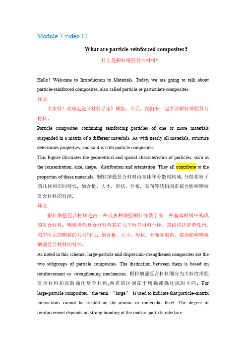
Particle composites containing reinforcing particles of one or more materials suspended in a matrix of a different materials. As with nearly all materials, structure determines properties, and so it is with particle composites.This Figure illustrates the geometrical and spatial characteristics of particles, such as the concentration, size, shape,distribution and orientation. They all contribute to the properties of these materials. 颗粒增强复合材料由基体和分散相构成,分散相粒子的几何和空间特性,如含量、大小、形状、分布、取向等结构因素都会影响颗粒复合材料的性能。
译文:颗粒增强复合材料是由一种或多种增强颗粒分散于另一种基体材料中构成的复合材料。
颗粒增强复合材料与其它几乎所有材料一样,其结构决定着性能。

alloys作主语-回复1. What are alloys?Alloys are metallic substances that are composed of two or more elements, including at least one metal. They are used extensively in various industries due to their unique combination of properties, such as strength, corrosion resistance, and high melting points. Alloys can be tailored to meet specific application requirements by adjusting their composition and processing methods.2. How are alloys formed?Alloys are formed through the process of alloying, which involves combining molten metals or mixing metal powders. The metals used in alloys can vary widely, including copper, aluminum, iron, nickel, titanium, and many others. They can also containnon-metals, such as carbon and silicon. The desired elements are melted or mixed together in precise proportions to achieve the desired alloy composition.3. What are the types of alloys?There are several types of alloys, each with its own unique properties and applications. Some of the common types of alloys include:- Steel: A combination of iron and carbon, steel is one of the most widely used alloys. It is known for its strength, durability, and versatility.- Bronze: Bronze is an alloy of copper and tin, known for its excellent wear resistance and corrosion resistance. It is commonly used in art, statues, and musical instruments.- Brass: Brass is an alloy of copper and zinc. It is valued for its superior machinability, decorative appeal, and acoustic properties. It is commonly used in plumbing fittings and musical instruments. - Stainless steel: Stainless steel is an alloy of iron, chromium, and nickel. It is famous for its exceptional corrosion resistance and strength. It is extensively used in kitchen appliances, cutlery, and construction materials.- Aluminum alloys: Aluminum alloys consist of aluminum as the primary metal, with other elements such as copper, manganese, and magnesium. These alloys are lightweight, corrosion-resistant and are widely used in aerospace, automotive, and construction industries.4. How are alloys used in various industries?Alloys play a crucial role in various industries due to their widerange of desirable properties. Here are some examples of how alloys are used in different sectors:- Automotive industry: Alloy wheels are extensively used in cars due to their lightweight and high strength, which improves vehicle performance and fuel efficiency. Additionally, alloy steels are used in engine parts, chassis, and suspension systems for their enhanced strength and durability.- Aerospace industry: Aluminum alloys, titanium alloys, and nickel-based alloys are commonly used in the aerospace industry due to their high strength-to-weight ratios, corrosion resistance, and ability to withstand extreme temperature variations.- Construction industry: Steel alloys, particularly reinforced steel bars, are used in construction for their exceptional strength and durability. Aluminum alloys are also used for their lightweight properties in various building components.- Electronics industry: Alloys are frequently used in electronic components and circuits. For example, solder alloys are used to join electronic components, while specific alloys with unique electrical and magnetic properties are used in semiconductors and magnetic devices.- Medical industry: Titanium and its alloys are commonly used inmedical implants and surgical instruments due to their biocompatibility, high strength, and corrosion resistance.In conclusion, alloys are versatile materials that have revolutionized various industries. Their unique properties and wide range of applications make them essential for everyday life. From transportation to construction and electronics, alloys are the backbone of modern technological advancements.。
金属材料专业英语词汇(99单词) metal: 金属ceramic: 陶瓷polymer: 聚合物Composites: 复合材料Semiconductors: 半导体Biomaterials: 生物材料Processing: 加工过程Structure: 组织结构Properties: 性质Performance: 使用性能Mechanical properties: 力学性能Electrical properties: 电性能Thermal behavior: 热性能Magnetic properties: 磁性能Optical properties: 光性能Deteriorative characteristics: 老化特性第二章原子结构与原子键Atomic mass unit (amu): 原子质量单位Atomic number: 原子数Atomic weight: 原子量Bohr atomic model: 波尔原子模型Bonding energy: 键能Coulombic force: 库仑力Covalent bond: 共价键Dipole (electric): 偶极子electronic configuration: 电子构型electron state: 电位Electronegative: 负电的Electropositive: 正电的Ground state: 基态Hydrogen bond: 氢键Ionic bond: 离子键Isotope: 同位素Metallic bond: 金属键Mole: 摩尔Molecule: 分子Pauli exclusion principle: 泡利不相容原理Periodic table: 元素周期表Polar molecule: 极性分子Primary bonding: 强键Quantum mechanics: 量子力学Quantum number: 量子数Secondary bonding: 弱键valence electron: 价电子van der waals bond: 范德华键Wave-mechanical model: 波粒二象性模型第三章金属与陶瓷的结构Allotropy: 同素异形现象Amorphous: 无定形Anion: 阴离子Anisotropy: 各向异性atomic packing factor(APF): 原子堆积因数body-centered cubic (BCC): 体心立方结构Bragg’s law: 布拉格定律Cation: 阳离子coordination number: 配位数crystal structure: 晶体结构crystal system: 晶系crystalline: 晶体的diffraction: 衍射face-centered cubic (FCC): 面心立方结构点群 point group对称要素 symmetry elements各向异性 anisotropy原子堆积因数 atomic packing factor(apf)体心立方结构 body-centered cubic (bcc)面心立方结构 face-centered cubic (fcc)布拉格定律 Braggs law配位数 coordination number晶体结构 crystal structure晶系 crystal system晶体的 crystalline衍射 diffraction中子衍射 neutron diffraction电子衍射 electron diffraction六方密堆积 hexagonal close-packed鲍林规则 Paulings rulesNaCl型结构 NaCl-type structureCsCl型结构 Caesium Chloride structure 闪锌矿型结构 Blende-type structure纤锌矿型结构 Wurtzite structure金红石型结构 Rutile structure萤石型结构 Fluorite structure钙钛矿型结构 Perovskite-type structure 尖晶石型结构 Spinel-type structure硅酸盐结构 structure of silicates岛状结构 island structure链状结构 chain structure层状结构 layer structure架状结构 framework structure 体材料 bulk material滑石 Talc叶蜡石 Pyrophyllite高岭石 Kaolinite石英 Quartz长石 Feldspar美橄榄石 Forsterite各向同性的 isotropic各向异性的 anisotropy晶格 lattice晶格参数 lattice parameters 密勒指数 miller indices非结晶的 amorphous多晶的 polycrystalline多晶形 polymorphism单晶 single crystal晶胞 unit cell电位 electron states(化合)价 valence电子 electrons极性分子 polar molecules原子面密度 atomic planar density 合金 alloy粒度,晶粒大小 grain size显微结构 microstructure重量百分数 weight percent四方的 tetragonal单斜的 monoclinic。
沈阳工业大学硕士学位论文Effect of Compacting Process Parameters and Heat TreatmentTechnology on Microstructure and Properties of 6061Aluminum Alloy作 者: 单位:指 导 教 师: 单位: 协作指导教师: 单位: 单位:论文答辩日期:2018年06月02日学位授予单位:沈 阳 工 业 大 学加压成形工艺参数和热处理工艺对6061铝合金组织及性能的影响都凯 材料科学与工程学院 材料科学与工程学院 材料科学与工程学院 袁晓光 教授 黄宏军 副教授摘要本文以6061铝合金为研究对象,采用正交试验,研究不同加压成形工艺参数对6061铝合金显微组织和力学性能的影响;通过SEM、DSC、TEM和拉伸试验等测试方法,研究了6061铝合金的最佳热处理工艺,探究6061铝合金的析出行为及强化机理;最后计算了6061铝合金β″相的析出动力学方程和TTT表达式。
研究表明,比压和模具预热温度对晶粒尺寸影响显著,随着比压和模具预热温度的提高晶粒尺寸分别由81.903μm和60.667μm变化为60.667μm和82.746μm,浇注温度和保压时间对晶粒尺寸无明显影响,随着浇注温度和保压时间的提高,晶粒尺寸变化在10μm之内。
各因素对抗拉强度的影响由大到小依次是:比压、模具预热温度、浇注温度和保压时间;各因素对伸长率的影响由大到小依次是:浇注温度、模具预热温度、保压时间和比压;当浇注温度720℃、比压150MPa、保压时间25s和模具预热温度150℃时,铸件抗拉强度为181.7MPa,伸长率为15.4%。
6061铝合金铸态结晶相有5种成分类型,分别为:AlCuMgSi、MgSi、AlFeSi、AlMnFeSi 和AlMnCrFeSi;4种结构类型,分别为:Al1.9CuMg4.1Si3.3相、Mg2Si相、β-Al5FeSi相和α-Al8Fe2Si相,其中β-Al5FeSi相包括Al5FeSi、Al5(MnFe)Si、Al5(MnCrFe)Si相,α-Al8Fe2Si 相包括Al8Fe2Si、Al8(MnFe)2Si、Al8(MnCrFe)2Si相。
Investigation of the influence of process parameters on hot extrusion of magnesium alloy tubesAbstract: During the hot extrusion of magnesium alloy, the change of process parameters will affect the mechanical properties of extruded products. In this study, Taguchi method and analysis of variance (ANOV A) are applied to analyze the influence of process parameters on the hot extrusion of magnesium alloy tubes under extrusion ratio of 21.05. The experiments are arranged by orthogonal array method in which magnesium alloys AZ31and AZ61 are used as outer arrays, the factors selected as inner arrays are the billet heating temperature, the initial extrusion speed, the container temperature and the lubricants. The extruded tubes will be carried out tensile test and flattening test, the test results are analyzed by the quality measurement of Taguchi method to find the relationship between the process parameters and mechanical properties of the products, and to acquire the optimal combination of parameters. Then based on the results obtained from the additive model, confirmatory experiments are performed. Besides, the microstructures of extruded tubes are observed to clarify the influence of process parameters on the grain size. Finally, with the same extrusion condition, the variations in tensile strength and flattening strength due to different compositions are discussed.© 2007 Elsevier B.V. All rights reserved.Keywords: Hot extrusion tube; Magnesium alloy; Mechanical properties; Taguchi method; Orthogonal array1. IntroductionMagnesium alloy has low specific gravity, high specific strength, good ventilation and shock absorption. It is also opaque to electromagnetic waves and recycle. In recent years, magnesium alloy has begun to replace steel, aluminum and plastic as products have become increasingly miniaturized. Magnesium alloy is 35% and 77% less dense than aluminum alloy and steel, respectively. Therefore, as lightweight products, environmental protection and recyclability become increasingly important, the demand for magnesium alloy has increased and been extensively applied to the automobile industry, the bicycle industry, the aerospace and national defense industries, the civic product manufacturing industry and the 3C (computer, communication and consumer electronic) electronic industry.At present, die casting is the main method for forming and processing magnesium alloy.Wu and Chang u sed the Taguchi method in the die casting of magnesium alloy to produce a cover for a personal data assistant (PDA), and thus to identify the optimal process parameters. Takudaetal adopted the finite element method to analyze the formability of AZ31 magnesium base material during deep drawing. Finiteelement analysis can be used to predict cracking position, which can then be verified experimentally. Chen et al.applied an AZ31 magnesium alloy sheet to study the deep drawing of a square cup. Following deep drawing at room temperature, the final sheet had defects, but at over 200 ◦C, the formability is improved. In a related study of magnesium alloy, Mwembelaetal.studied the microstructure of AZ31 magnesium alloy during hot working.A high temperature of 300–450°C was firstly employedfor rolling, which was followed by forging. As the temperature increased over 300°C, the grains grew, and the strength of the alloy decreased.In a study of the extrusion of magnesium alloy, Gouveiaetal. used the finite-element method to simulate forming by cold forward extrusion. Chandrasekara and Shyan John investigated three magnesium alloys, AZ31, AZ61 and ZK60, as well as the effect of temperature on formability during forward extrusion. They showed that these magnesium alloys cannot be formed at between room temperature and 175 ◦C, and that these magnesium alloys can be extruded smoothly at 200 ◦C, but AZ31 and ZK60 magnesium alloys exhibit cracking. When the temperature was increased to 300 ◦C, the AZ31 magnesium alloy could be well formed. Mural et al. empolyed AZ31B magnesium alloy billets formed by casting, as well as homogenized materials to perform extrusion.The microstructure and mechanical properties of the final products were then studied. Using the Taguchi method for plastic processing does not reduce the accuracy of the experimental results, but significantly reduces the number of times the experiments must be performed. It is therefore regarded as a more effective study method.In this study, two magnesium alloy billets, AZ31 and AZ61,are applied to carry out hot extrusion into a tube with a thickness of 2 mm. The Taguchi method is initially applied in the experimental planning and the process parameters of hot extrusion are set to optimize the mechanical properties for AZ31 and AZ61 tube. ANOV A is then employed to analyze the effect of the process parameter on the tube. Finally, the effects of the initial extrusion speed and the lubricant on the mechanical properties of the tube are investigated.2. The principles of quality design—Taguchi methodThe experiments can be planned in four ways: (1) trial-and-error;(2) one-factor-at-a-time experiments; (3) full-factorial experiments; and (4) Taguchi’s orthogonal arrays (OA).Orthogonal arrays can eliminate the bias produced by one-factor-at-a-time experiments, and improve the experimental efficiency of full-factorial experiments. Based on the principle of maintaining the accuracy of experiment results, the use of orthogonal arrays can considerably reduce the time required to perform the experiments, and increases the reproducibility of the experiment results. This method can also be employed to optimize the process parameters. Therefore, orthogonal arrays are applied herein to perform experimental planning.2.1. Experimental planning methodThe Taguchi method uses the signal-to-noise ratio (S/N) as a quality benchmark,based on the ideal function, different measures are used for the various quality properties. S/N ratios are one of the three forms – the normal-the-best, the smaller-the-better and the larger-the-better. The mechanical property discussed herein is tensile strength. It is the larger-the-better characteristic. Therefore, an S/N ratio that is the larger-the-better is used, and is given in Eq. (1).(1)in the equation, n stands the total number of measurements, and yi the measured quality value. The i in the suffix refers to the number of the experiment in the plan based on orthogonal arrays, and the calculated S/N ratio is used in the factor response statistical analysis, and the optimal combination of process parameters can be obtained.2.2. Application of analysis of varianceThe statistical analysis of variance (ANOV A), used in the Taguchi method, is adopted mainly to evaluate the significance level of experimental errors and every factor response. The equationsused in the ANOV A statistical analysis in this study are as follows.(1) Sum of squares of the factor effect vector, SS factor(2)where n is the number of times the experiment is performed, r is the number of times the experiment is repeated, L is the number of factor levels, yk is the response value of that factor at level k , and ym is the average of all experimental data.(2) Sum of squares of the total variation vector, SS total(3)where yij stands for the j experiment data of the its set of experiment.(3) Error sums of squares, SS eSS e = SS total – SS factor (4)(4) Degree of freedom of the factor effect vector, DOF factorDOF factor = L − 1 (5)(5) Degree of freedom of the total variation vector noises,DO factorDO factor = n × r − 1 (6)(6) Variance of the factor, Viii i DOF SS V = (7) (7) Distribution of the predicted values of the two variances, FVerrorfactor factor V F = (8)where V error stands for the variance caused by errors.(8) Contribution, σi(9)(9) Experimental error, S(10)3. Experimental planningThis study involves (1) the hot extrusion process, in which the tubes are analyzed by the Taguchi method, and the optimal combination of process parameters for a best mechanical properties can be obtained; (2) the effect of the initial extrusion speed and the lubricants on the mechanical properties of the tubes; (3) the effect of the initial extrusion speed and the lubricants on the microstructure of the tubes; and (4) the use of ANOV A to analyze the degree of influence of the process parameters on the tubes. Fig. 1 shows the Taguchi experimental planning procedure.3.1. Extrusion process and billetExtrusion forming involves placing billet into a container and then applying pressure to them to cause plastic deformation. They are then extruded along the holes of the extrusion die, giving the final product a long stripe with either a concrete or a vacuum center, and an evenly distributed cross-section. Fig. 2 schematically depicts the hot extrusion process. However, during the hot extrusion forming of the tubes, the billet flows into the die from three channels at the extrusion end of the die, and then passes through the welding chamber of the die to be connected to form good tubes. The geometric variance associated with the extrusion process is the ratio between the cross-sectional area of the billets and that of the final product. This is known as the extrusion ratio, and is given by Eq. (11). The billets used in this paper are Ø80mm×150 mm, and their elemental composition is as shown in Table 1. After extrusion, the outer diameter of the tubes is Ø40 mm; the inner diameter is Ø36 mm, the thickness is 2 mm, and the extrusion ratio is 21.05. Extrusion ration =to A A (11) where A o represents the cross-sectional area of the billets and A f is the crosssectional area of the final product. This study involves direct hot extrusion processing. The pre-process involves putting the lubricant on the die and the billets, and then putting them in a furnace to be heated. The container is simultaneously preheated for 5.5 h, before extrusion forming.3.2. Experimental planning of L9 orthogonal arrayBefore the planning orthogonal array (OA) can be implemented, trial and error is applied to determine the control factors of the hot extrusion. This method seeks the levels of the control factor during hot extrusion. Its factor level is set as shown in Table 2, and the final extrusion speed is 1 mm/s. Billets of AZ31 and AZ61magnesium alloy are the outer OA, and the control factors of the inner OA are billet heating temperature, initial extrusion speed, container temperature and lubricant, each control factor has three levels. Their innerOAis an L9 orthogonal array, and the orthogonal array is set as shown in Table 3.3.3. Test of mechanical propertiesThe tube flattening test, as specified by CNS 13868 (JIS H4090), is used for reference.A50mmtrial piece is cut from the tube, which is then pressed between the two plates of a testing machine that weighs 30 tonnes. The welded zone is placed at the position of the pressing direction, where it forms a perpendicular angle. During the flattening test, the flattening speed is 7.16 mm/min. When the plates are at H= 0.75 D, the wall of the tube is observed to identify any breaking or cracking. The tensile test is performed according to specifications CNS 2111 and CNS 2112, with a tensile speed of 16.5 mm/min.4. Results and discussionThe magnesium alloys used in this study are AZ31 and AZ61, which are used to carry out hot extrusion into a tube with a thickness of 2 mm. The final of the experiment based on the orthogonal array was performed must then undergo tensile and flattening tests, to understand the mechanical properties of the tube. Also, the tensile strength from the tensile test was analyzed by measuring the quality characteristics and by performing ANOV A, to determine the optimal combination of process parameters and the importance of each factor. Finally, a confirmatory experiment is performed to verify its accuracy.4.1. Analysis of flattening tes tThe flattening test is conducted with reference to the relevant specifications. When the distance between the two plates is H= 30 mm, the wall of the tube is examined to see whether any breaking or cracking has occurred. Table 4 shows that when H= 30 mm, no breaking is observed in the tubes made from two set of billets AZ31 and AZ61, the bearable loading of the AZ31 tube is between 1765.80 and 2313.20 N, and the bearable loading of AZ61 is 1827.60 and 2109.15 N. When theflattening test is continued until the tube breaks, the loading of the AZ31 tube is 2416.20N or above, while that of the AZ61 tube is at least 2820.38 N. Comparing these two sets of billets reveals that when H= 30mm and they start to break, the more AZ61 tube can bear a higher loading than the AZ31 tube.4.2. Optimal process parameters for maximizing the tensile strength of the tubeTable 5 presents the results of the tensile strength experiment for the tube. This results in this table show that the mean tensile strength of the AZ31 tubes is distributed from 261.08 to 296.20MPa, and that of the AZ61 tube is distributed from 263.97 to 299.44MPa. The tensile strengths of the AZ31 billets and the AZ61 billets before extrusion are 239.70 and 230.21MPa. The comparison shows that the tube that underwent hot extrusion has a higher tensile strength.The greater tensile strength of a tube corresponds to higher quality. Therefore, the S/N ratio is calculated as a larger-is-better value, using Eq. (1), it is as indicated in Table 5. Figs. 3 and 4 show the results analyzed by the factor effect diagram that isconstructed from the S/N values in Table 5. The largest S/N value from this figure yields the optimal combination of process parameters.The process parameters considered in this study are billet heating temperature, initial extrusion speed, container temperature and type of lubricant. The factor effect figure, Fig. 3,reveals that the optimal combination of process parameters for the hot extrusion of AZ31 tube is heating temperature of billet = 320 ◦C, initial speed of extrusion = 2 mm/s, container temperature = 300 ◦C and a BN lubricant The factor effect figure, Fig. 4, reveals that the optimal combination of process parameters for AZ61 tube is heating temperature of billet = 320 ◦C, initial speed of extrusion = 2 mm/s, container temperature = 350 ◦C and a graphite lubricant.In the quality property analysis of a magnesium alloy tube, the tensile strength must be considered. The extruded tube using the aforementioned optimal combination of process parameters yields a product with the highest tensile strength.4.3. Confirmation experimentThe aforementioned analyzed optimal combination of process parameters must be further verified experimentally, to confirm its accuracy. In the verifying experiment for the AZ31tube, only the initial extrusion speed is changed (2, 3 and4 mm/s), while all other factors remain unchanged. In the verifying experiment for the AZ61 tube, only the lubricant is changed (BN, graphite andMoS2), while all other factors remain unchanged. Finally, the tensile strength and microstructures of the extruded tubes are compared.Table 6 presents data on the tensile strength obtained in the verifying experiment. The first set of data concern the extrusion of the AZ31 tube. The initial extrusion speed is varied, and the tensile strength is highest at an initial extrusion speed of 2 mm/s, followed by that at 4 mm/s and then at 3 mm/s. This result is consistent with Fig. 3. The microstructure shown in Fig. 5 reveals that the sizes of the grains of the billets all exceed those of the tube after extrusion. Extrusion considerably reduces the sizes of the grains, which is beneficial to the strengthening of the tube.In the verifying extrusion experiment on the second set of AZ61 tubes, only the lubricant is changed. The results show that when the lubricant is graphite, the tensile strength is the highest, followed by that using BN and then MoS2. This results are consistent with Fig. 4. The microstructure displayed in Fig. 6 shows that the size of the grains in the billet of AZ61 differs considerably from that of the grains in the tube. Extrusion reduces and homogenizes the sizes of the grains.4.4. Analysis of varianceANOV A analysis adopts Eqs. (2)–(10). ANOV A is used to evaluate the tensile strengths of the AZ31 and AZ61 tubes, and the results shown in Tables 7 and 8. With 99.9% confidence, for both AZ31 and AZ61 tubes, the F value exceeds 10.49(F = FINV(0.001,2,18) = 10.39), and therefore, the control factors A, B, C and D have a strong influence. Also, for both AZ31 or AZ61 tubes, the strengths of the effects of the control factors follow the same order –(A) billet heating temperature; (B) initial extrusion speed; (D) lubricant; and (C) container temperature. This order is also obtained in Section 4.2. And inANOV Aanalysis, billet heating temperature has the strongest effect. Therefore, the most important factor that governs the tensile strengthof the tube is the billet heating temperature, such that during the extrusion, the change in the billet heating temperature considerably affects the tensile strength of the tube.5. ConclusionsIn this study, AZ31 and AZ61 magnesium alloy tubes were used to carry out hot extrusion processing. After undergoing measure of quality and ANOV A analysis of the mechanical properties of the final product obtained by extrusion yields the following conclusions.1. In the flattening test, the tubes reach the relevant specifications. The breaking loads of the AZ31 and AZ61 tubes exceed 2416.20 and 2820.38 N, the breaking load of AZ61 tube generally exceeds that of the AZ31 tube.2. The average tensile strength of the AZ31 tube is distributed between 261.08 and 296.20MPa, whereas that of the AZ61 tube is distributed between 263.97 and 299.44MPa3. The optimal combination of process parameters that maximizes the tensile strength of the AZ31 tube formed by hot extrusion is heating temperature of billet = 320 ◦C, initial speed of extrusion = 2 mm/s, container temperature= 300°C and a BN lubricant. The optimal combination of process parameters that maximize the tensile strength of the AZ61 tube formed by hot extrusion is heatingtemperature of billet = 320 ◦C, initial speed of extrusion= 2 mm/s, container temperature = 300°C and a graphitelubricant.4. Two sets of billets of AZ31 and AZ61 were used, and the strengths of the effects of the factors on the tensile strength of the tube follow the order, heating temperature of billet, initial speed of extrusion, type of lubricant and container temperature.5. Regardless of the billet used (AZ31 or AZ61), extrusion processing considerably reduces the sizes of the grains, increasing the strength of the tube.关于工艺参数对热挤压镁合金影响的研究摘要:在热挤压镁合金时,工艺参数的改变会影响挤压件的机械性能。
哈尔滨工业大学硕士学位论文AbstractIn this paper, we study the influence of the Ga addition on microstructure and mechanical property of Nb-Si alloy. We study the formation of solidification microstructure of Nb-Si alloy through OM, XRD and SEM. We test and compare the mechanical property of arc melting alloy with different Ga addition and heat treatment through Gleeble-1500 Thermal Simulator, Universal Testing Machines and Micro Hardness Tester.The volatile components of Arc-melted Nb-16Si-xGa alloy are Si and Ga. The evaporation rate of Ga is less than Si. Ga addition on Nb-16Si alloy is conducive to the generation of Nbss+Nb5Si3 eutectic. The microstructure of Nb-16Si-5Ga alloy consists of Nbss+Nb5Si3 eutectic. The room temperature strength and ductility is improved with Ga addition on Nb-16Si alloy, but too much Ga will decrease the room temperature strength. The variation of high temperature strength is similar to the variation of room temperature strength. Too small Nb5Si3 can not provide sufficient resistance to deformation. The room temperature fracture toughness of Nb-16Si-xGa alloy increases with Ga addition. Small Nbss+Nb5Si3 eutectic structure is good for the fracture toughness.With the Ga addition on Nb-16Si-22Ti-2Hf-2Al-2Cr alloy, hypoeutectic composition is converted into hypereutectic composition. Nb3Si is decreased and Nb5Si3 is gradually increased. The room temperature strength and ductility, high temperature strength and room temperature fracture toughness is increased and then decreased with Ga addition on Nb-16Si-22Ti-2Hf-2Al-2Cr alloy. Nbss+Nb5Si3 eutectic structure is conducive to the fracture toughness. The block silicide is not conducive to the compression performance of materials at room or high temperature.The Ga causes Nb3Si phase eutectoid transformation in Nb-16-xGa alloy at ℃5Si3 eutectic provides the nucleation substrate for eutectoid 1250. Nbss+Nb℃phase of transformation. Heat treatment at 1250 for 10 hour enables the silicideNb-16Si-22Ti-2Hf-2Al-2Cr-xGa alloy to become smaller and round, but Nb3Si phase eutectoid reaction does not occurs.Keywords: Nb-Si alloy,Ga addition,microstructures,mechanical properties,heat treatment哈尔滨工业大学硕士学位论文目录摘要 (I)ABSTRACT (II)第1章绪论 (1)1.1课题背景及研究的目的和意义 (1)1.2国内外研究现状 (3)1.2.1 高温结构材料 (3)1.2.2 Nb-Si基原位自生复合材料 (3)1.3合金化对材料组织和性能的影响 (7)1.3.1 Nb-Si合金共析转变 (7)1.3.2 合金化对Nb-Si合金组织的影响 (8)1.3.3 合金化对材料力学性能的影响 (10)1.4本文的主要研究内容 (12)第2章试验材料与试验方法 (14)2.1试验材料 (14)2.2试验方法 (15)2.2.1 合金锭的制备 (15)2.2.2 热处理工作 (15)2.2.3 显微组织分析 (16)2.2.4力学性能测试 (16)第3章 Ga对Nb-Si合金组织和力学性能的影响 (18)3.1Nb-Si-Ga三元合金的熔炼 (18)3.1.1 活度的计算 (18)3.1.2 挥发损失计算 (22)3.2Ga含量对Nb-Si合金组织的影响 (24)3.2.1 Nb-16Si-xGa合金的宏观组织 (24)3.2.2 Nb-16Si-xGa合金的显微组织 (24)3.3Ga含量对Nb-Si合金力学性能的影响 (28)3.3.1 Nb-16Si-xGa合金的室温压缩性能 (28)3.3.2 Nb-16Si-xGa合金的高温压缩性能 (29)3.3.3 Nb-16Si-xGa合金的室温断裂韧性 (30)哈尔滨工业大学硕士学位论文3.4Ga对Nb-Si合金高温稳定性的影响 (31)3.4.1 Ga对Nb3Si热处理共析转变的影响 (31)3.4.2 热处理对Nb-16Si-xGa合金组织的影响 (33)3.5热处理对Nb-Si-Ga合金显微硬度的影响 (34)3.6本章小结 (34)第4章 Ga对Nb-Si多元合金组织和力学性能的影响 (36)4.1Ga含量对Nb-Si-Ti-Hf-Al-Cr合金组织的影响 (36)4.2Ga含量对Nb-Si-Ti-Hf-Al-Cr合金学力学性能的影响 (40)4.2.1 Nb-16Si-22Ti-2Hf-2Al-2Cr-xGa合金的室温压缩性能 (40)4.2.2 Nb-16Si-22Ti-2Hf-2Al-2Cr-xGa合金的高温压缩性能 (42)4.2.3 Nb-16Si-22Ti-2Hf-2Al-2Cr-xGa合金的室温断裂韧性 (42)4.3Ga对Nb-Si-Ti-Hf-Al-Cr合金高温稳定性的影响 (44)4.4热处理对Nb-Si-Ti-Hf-Al-Cr-Ga合金显微硬度的影响 (46)4.5本章小结 (47)结论 (48)参考文献 (49)哈尔滨工业大学学位论文原创性声明和使用权限 (54)致谢 (55)哈尔滨工业大学硕士学位论文第1章绪论1.1 课题背景及研究的目的和意义过去50年里,高温材料性能的改善促进了航空发动机和地面燃气涡轮性能的提高[1]。
Contents1 Definitions 32 Limitations and Explanations - Density Calculations 42.1 Requirement 43 Density and Atomic Number - Influence of Different Radiation Types 54 Calculation of the Density Influence 55 Calculation of the Atomic Number Influence 6Record 8 6 RevisionsRevision of the laboratory report EKL3 - 11 360/1 in respect of the factors influencing the density and atomic number.1 Definitions### =DensityZ = Atomic numberBase density = Density of the alloy base materiale.g. Al = 2.7 kg/dm 3 or Fe = 7.86 kg/dm 3Alloy density = Alloy densityMk = Mass absorption coefficientG % (x) = Percentage weight of the alloy component xAi ()ρ = Absorption index of the alloy (dependent of the density change)Ai z ()=Absorption index of the alloy (dependent on the atomic number)Ai = Total absorption index ()Ai Ai z ()()ρ⋅ for thickness measuring equipment forwhich Ai ()ρ and Ai z () are not given separately.Ai cor x z ()()−= The correction factor for the alloy component x and the used type ofradiation, taking into account the atomic number of the base material.Ai cor x z ()()−=−Mk of the alloy componentMk of the base material1Ai cor x ()()ρ−=The density correction factor for the alloy component x, taking the basematerial into account.Ai cor x ()()ρ−=⋅−Density of the alloy components Fact.Base dinsity12 Limitations and Explanations - Density CalculationsThe values Ai cor x ()()ρ− for Fe (table 1 on page 4) can be correct, but most probably are incorrect, because the tabulated values are based on the elements being in adjacent lattices (substitutional solid solution), i.e. the factor in the Ai cor x ()()ρ− equation is 1.Because of the complexity of the alloy composition the degree of inclusion of foreign atoms between the base atoms in a lattice (interstitial solid solution) or replacement of atoms in the base lattice with foreign atoms (substitutional solid solution) cannot be estimated.Safe results such as the calculation carried out on the basis of the material composition analysis give a density of the actual alloy for measurement purposes.The values Ai cor x ()()ρ− for Al are empirical values, i.e. the factor in the Ai cor x ()()ρ− equation is different from 1.(Source: Values from Chemical Handbook by van Horn.)2.1 RequirementBecause the radiometric thickness measurement is based on the measurement of the area weight it is necessary to take into account the density of the measured material. measured thickness = measured area weight / base material density3 Density and Atomic Number - Influence of Different Radiation TypesFor a thickness gauge system, calibrated using a base density, with beta or gamma sources of mid range energy (Compton effect e.g. Cs 137 with ca 660 keV) it is advisable, when deviating from the base density, to take into account the alloy inclusion densities as follows:Density measured densityAi ()=ρIf the alloy density is known, the value of Ai ()ρ can easily be determined.Ai ()ρ=Alloy densityBase densityIf the alloy density is unknown, it must be determined using the following calculation method.In addition to the previously explained density influence it should be mentioned that for thickness measuring systems with low energy gamma radiation (photon-effect e.g. Am 241 with ca 60 keV, or Cm 244 with ca 20 keV) elements with different atomic numbers induce different absorption's.For identical types of radiation (with the same energy) this can be attributed to the material specific mass absorption coefficients (dependent on the atomic number).This means that if an alloy dependant absorption index Ai is required, the values of Ai (###) and Ai (Z), must be known. Ai Ai Ai z =⋅()()ρIn order to determine in advance the magnitude of the above described influences it is necessary to do this based on the material analysis, separately for Ai ()ρ and Ai z (), with the aid of table1 on page 4.4 Calculation of the Density Influence()Ai SUM G x Ai cor x ()()%()()ρρ=+⋅−⎛⎝⎜⎞⎠⎟1100(SUM = Sum of (..+..+..)) Alloy density = Base density ⋅Ai ()ρ5 Calculation of the Atomic Number Influence()Ai SUM G x Ai cor x z z ()()%()()=+⋅−⎛⎝⎜⎞⎠⎟1100(SUM = Sum of (..+..+..))Table 1Ai cor x ()()ρ− forAi cor x z ()()−forBasic MaterialBasic Material/Source ElementZDensityAl Fe Al / Cm 244 Am 241 Fe /Am241B 5 2,34 -0,659 -0,81 -0,36 -0,86C 6 2,25 -0,671 0,88 -0,35 -0,85 Mg 12 1,74 -0,52 -0,779 -0,24 -0,11 -0,80 * AL 13 2,70 0 -0,613 0 0 -0,78Si 14 2,35 -0,11 -0,658 0,24 0,12 -0,755 P 15 2,20 -0,677 0,51 0,27 -0,72 S 16 2,00 -0,703 0,81 0,40 -0,69 Ca 20 1,55 -0,803 2,65 1,36 -0,46 Ti 22 4,50 0,41 -0,384 3,90 2,04 -0,33 V 23 6,10 -0,16 4,60 2,40 -0,26 Cr 24 7,20 0,63 -0,036 5,20 2,76 -0,18 Mn 25 7,42 0,63 -0,013 6,00 3,19 -0,09 * FE 26 7,86 0,67 0 6,80 3,52 0 Co 27 8,71 0,151 7,60 4,00 0,11 Ni 28 8,86 0,170 8,40 4,45 0,20 Cu 29 8,90 0,7 0,175 9,24 5,08 0,34 Zn 30 7,14 0,63 -0,071 10,20 5,52 0,46 Ga 31 5,91 -0,209 11,08 6,20 0,62 Zr 40 6,49 -0,102 21,00 13,60 2,22 Nb 41 8,57 0,133 23,10 14,50 2,42 Mo 42 8,86 0,298 0,170 24,2 15,5 2,69 Sn 50 7,30 -0,042 4,58 25,15 4,79 W 74 19,3 1,455 14,86 9,46 1,31 Pb 82 11,3 0,481 19,91 12,85 2,06The elements marked with x are frequently used in the respective alloys.Table 2Fe - AlloysElement Z Al - Alloyscomplex alloy steels B 50,1...0.65%C 6 xN 7Mg 12 xAl 13 x x 0 ( up to 0.3 % )Si 14 x x 0,1...0.4 % ( up to 1 % )%0,1 (1)P 15 x%0...0.06S 16 xCa 20Ti 22 x x 0 ( up to 0.7 %)V 23 x 0...0.2 % ( up to 20 % )Cr 24 x x 0...2.5 % ( up to 20 % ) Mn 25 x x 0...1.5 % ( up to 2 % ) FE 26 x xCo 27Ni 28 x 0...2 % ( up to 15 % ) Cu 29 xZn 30 xGa 31Zr 40Nb 41 x 0 ( up to 1.5 % ) Mo 42 x 0...0.5 % ( up to 3 % ) Sn 50W 74 xPb 826 Revisions RecordPage Updating State Page Updating State Page Updating StateA B C D E F A B C D E F A B C D E F1 34 672 35 683 36 694 37 705 38 716 39 727 40 738 41 749 42 7510 43 7611 44 7712 45 7813 46 7914 47 8015 48 8116 49 8217 50 8318 51 8419 52 8520 53 8621 54 8722 55 8823 56 8924 57 9025 58 9126 59 9227 60 9328 61 9429 62 9530 63 9631 64 9732 65 9833 66 99Edition Updating Date Prepared Date Checked ABCDEF。