
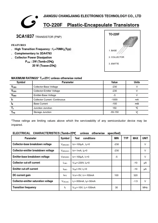
3CA1837-TO-220F中文资料
- 格式:pdf
- 大小:105.31 KB
- 文档页数:2

FeaturesLED Driver• 3W Class II AC-DC LED power supply • 350mA, 500mA and 700mA CC/CV output • Fused input and SCP , OVP , OLP , OTP • 3kVAC isolation • IP66 rated •Low costRACD03AC/DC ConverterDescriptionA compact universal AC input 3W constant current switching power module suitable for driving 1 - 6high power LEDs. The output (dual constant voltage / constant current mode) current limit is fixed at 350mA, 500mA or 700mA. At lower output currents, the output is constant voltage. Connections are via118mm long flying leads.E3406963 Watt CC/CVSingle OutputUL8750 certified UL1310 certifiedCAN/CSA-C22.2 No. 223-M91 certified IEC/EN61347 certifiedIEC/EN61347-2-13 certified ENEC certified CB reportSelection GuidePart Input CC CV (1)Efficiency Rated Number Voltage RangeMode Mode typ. Power nom./max.[VAC] [VDC] [mA] [VDC] [mA] [%] [W]RACD03-350 90-264 3-12 350 15 0-300 72 3 / 4.2RACD03-500 90-264 3-9.5 500 none71 3 / 4.6RACD03-70090-2643-4.5 70060-600623 / 3.1BASIC CHARACTERISTICSParameterCondition Min.Typ.Max.Input Voltage Range 90VAC 230VAC264VAC 120VDC370VDC Input Current full load, 100VAC 110mA Inrush Current 230VAC, <2ms10A Input Frequency Range 47Hz 63HzPower Factor full load, 230VAC 0.55Hold-up Time 18msOutput Ripple Current100mAp-pcontinued on next page Specifications (measured @ Ta= 25°C, nom. Vin, rated load and after warm-up unless otherwise stated)All LED Drivers may not be used without a load. They must be switched on the primary side only.Noncompliance may damage the LED or reduce its lifetime.Model Numberingnom. Output PowerRACD03-___nom. Output CurrentSpecifications (measured @ Ta= 25°C, nom. Vin, rated load and after warm-up unless otherwise stated)ENVIRONMENTALParameterConditionValueOperating Temperature Range according to UL according to ENEC-20°C to +50°C -20°C to +40°CMax. Case Temperature according to UL according to ENECRACD03-350, RACD03-700RACD03-500+67°C +65°C +75°CIP Rating IP66Operating Humidity non condensing 5% - 85% RH max.Design Lifetime+25°C ambient 20 x 103 hourscontinued on next pagePROTECTIONParameterCondition ValueInput Fuse(2)T1A, slow blowShort Circuit Protection (SCP)continuous, current limitOverload Protection (OLP)120% typ.Output Over Voltage Protection (OVP)zener diode clampRACD03-350RACD03-500RACD03-70017VDC max.14VDC max.8VDC max.Over Temperature Protection (OTP)shutdown, automatic resatart after cooling down Isolation Voltage I/P to O/P3.75kVAC/1 minute typ. / 3kVAC/1 minute min.Leakage Current0.2mA typ.Maximum loading of automatic circuit breakers*Circuit BreakerCircuit Breaker CurrentTyp 10A 16A 20A 25A C221247337430Circuit BreakerCircuit Breaker CurrentTyp 10A 16A 20A 25A B 80157200254C265317437550* @ 115VAC, 1Ohm, 90° phase angle and max. load* @ 230VAC, 1Ohm, 90° phase angle and max. loadNotes:Note2: Refer to local wiring regulations if input over-current protection is also requiredSpecifications (measured @ Ta= 25°C, nom. Vin, rated load and after warm-up unless otherwise stated)SAFETY AND CERTIFICATIONSCertificate Type (Safety)Report Number Standard Standard for LED Equipment for use in Lighting Products E340696-1-4UL8750, 1st Edition, 2009Standard for Class 2 Power Units UL1310, 6th Edition, 2011Extra Low Voltage Class 2 Outputs CAN/CSA-C22.2 No. 223-M91, 2nd Edition, 2009Lamp Controlgear Particular Requirements SH12051509-001IEC/EN61347-2-13,2006Lamp Controlgear General Requirments for Safety IEC61347-1, 2nd edition, 2010EN61347-1, 2nd edition, 2011Safety of control gear for LED modules (CB Scheme)12CA61285-1IEC/EN61347-2-13,2006Safety requirements for lamp controlgear (CB Scheme)IEC61347-1, 2nd Edition, 2010EN61347-1, 2nd Edition, 2011Lamp Controlgear General Requirments for Safety (ENEC License) ENEC-00611EN61347-1Lamp Controlgear Particular Requirements (ENEC License)EN61347-2-13D.C. or A.C. Controlgears for LED Performance Requirements (ENEC License)EN62348, 2006RoHS RoHS 6/6, 2011/65/EU EACRU Д- AT.A Г03. В.67369TP TC 004/020, 2011EMC ComplianceCondition Standard / CriterionEMC for industrial, scientific and medical equipment (design to meet)FCC18, Class A Limits and methods of measurement of radio disturbance characteristics of electrical lighting and similar equipment (design to meet)EN55015, Class ACISPR15, 7th Edition, 2009Electromagnetic compatibility - Requirements for household appliances, electric tools and similar apparatus - Part 1: Emission (design to meet)EN55014-1Limits of harmonic current emissionsVoltage Fluctuations and Flicker in Public Low-Voltage Systems <=16A per phaseIEC61000-3-2, 3rd Edition, 2009IEC61000-3-3, 2nd Edition, 2008Derating Graph-20-101020304050601008060409070503020100O u t p u t L o a d [%]Ambient Temperature [°C]Specifications (measured @ Ta= 25°C, nom. Vin, rated load and after warm-up unless otherwise stated)TypeUL-1007, AWG18UL-1007, AWG18PACKAGING INFORMATIONParameter Type Value Packaging Dimension (LxWxH) cardboard Box265.0 x 80.0 x 115.0mm Packaging Quantity10pcs Storage Temperature Range-30°C to +80°C Storage Humidity non-condensing5%-85% RHThe product information and specifications may be subject to changes even without prior written notice.The product has been designed for various applications; its suitability lies in the responsibility of each customer. The products are not authorized for use in safety-critical applications without RECOM’s explicit written consent. A safety-critical application is an application where a failure may reasonably be expected to endanger or cause loss of life, inflict bodily harm or damage property. The applicant shall indemnify and hold harmless RECOM, its affiliated companies and its representatives against any damage claims in connection with the unauthorizeduse of RECOM products in such safety-critical applications.。

Features• 1 location for SPI-2 or MVA interchangeable board• 3 reverse relays 3 A/230 Vac• 24 Vdc/Vac or 115/230 Vac power supply• Outputs diagnosticPossible optional measurementsThe following probes and boards are available as option for C310 transmitters. ForWarning: risk of electric shock3 x 0/4-20 mA or 3 x 0-5/10 V (4 wires)Common mode voltage <30 VAC DOUBLE ISOLATION or REINFORCED ISOLATIONAll dimensions are in millimeters.Relays and alarmsCA310 transmitter has 3 independent and configurablealarms: these are visual and audible alarms and it ispossible to couple them with 3 relays.Available settings:• Selection of the parameter (pressure, air velocity,temperature,...)• Time-delays durations from 0 to 600 s• Alarm action: rising edge, falling edge, monitoring orstate of the transmitter• Operating mode of the relays: negative or positivesafety• Activation of the audible alarm (buzzer), that can beacknowledge by the front keypadEthernet board (optional)Class 310 transmitters can be linked in one network operating on a RS485 home bus.The RS 485 digital communication is a 2-wire network, on which the transmitters are connected in parallel. They are connected to a PLC/BMS via the RTU Modbus communication system. Since the C310 can be configured with the keypad, the MODBUS enables remote configuration, to measure 1 or 2 parameters or to see the status of the alarms...RS 485 Modbus Protocol (optional)An Ethernet board can put put on a CA310 transmitter allowing for each transmitter to have a specific configurable IP address. So the user can remotely interrogate the transmitter, retrieve data, modify the configuration, ...It is also possible to integrate CA310 transmitters into a computer network via the RJ45 connection located at the bottom of the transmitter.ConnectionsP h a s e (N e u t r e (T e r r e f o n c t i o nP h a s e (N e u t r e (T e r r e f o n c t i o n n12345116Relay 1C O M : c o m m o n N C : n o r m a l l y cl o s e dN O : n o r m a l ly op e ne 79(OUT2)(a)Relay 2For 24 Vdc/Vac power supply models: (c)s e (L ) +a l (N ) -O p e r a t i o u n d i ngFor 115 Vac to 230 Vac power supply models:P h a s e (L ) ~N e u t r a l (N ) ~O p e r a t i o n a l g ro u n d i n gModbus(d)1 2 31012138(b)G N D – G r o u n 0/4-20 m A – C u r r e n 0-5/10 V – V o l t a gC O M : c o m m o n N C : n o r m a l l y c l o s e dN O : n o r m a l l y o p e n eorPe N L240 VacAlimentation 24 VacN D /4-20 m A 0-5/10 V-+Af cheur régulateur ou automate type passif N D 4-20 m A 5/10 V-+Af cheur régulateur ou automate type passifG N D 0/4-20 m A 0-5/10 VN D /4-20 m A -5/10 V• 0/4-20 mA current output connection:• 0-5/10 V voltage outputconnection:1. LCC-S software connection2. Autozero3. Solenoid valve4. RS 485 connection (d) (optional)5. SPI-2 board (optional)6. Ethernet connection (optional)7. Analogue output (a)8. Relays (b)9. Power supply terminal block (c)10. Type of power supply of the transmitter 11. Probe connection12. Pressure connections (optional)13.Cable glandsConfigurationMountingInstall the mounting bracket in horizontal position along a plane wall (see below dimensions / drilling drawing). Put the display inside the mounting bracket, with the 2 screws. Remove the screw covers located on the right and left side of housing, in order to have access to the 4 shutting screws. Make the electrical connection with the connection glands, with soft cable Ø7 mm maximum. Close the housing before powering on.MaintenanceAvoid aggressive solvents. When cleaning rooms or ducts with products containing formol, protect the the transmitter.CalibrationOutputs diagnostics: with this function, you can check with a multimeter (or on a regulator/display, or on a PLC/BMS) if the transmitteroutputs work properly. The transmitter generates a voltage of 0 V , 5 V and 10 V or a current of 0 mA, 4 mA, 12 mA and 20 mACertificate: transmitters are supplied with an individual adjusting certificate and can be supplied with a calibration certificate as an option.Precautions for usePlease always use the device in accordance with its intended use and within parameters described in the technical features in order not to compromise the protection ensured by the device.Only the accessories supplied with the device must be used.Class 310 transmitters allows you to set all the parameters managed by the transmitter: units, measuring ranges, alarms, outputs, channels... via the different methods shown below:• Via keypad, only on models with display. A code-locking system for keypad guarantees the security of the installation. See configuration manual.• Via software (optional): simple and user-friendly. See LCC-S user manual.• Via Modbus (optional): configuration of all parameters from your PC, via the supervision or data acquisition software.•Via Ethernet (optional): configuration of all parameters from your PC, via the supervision or data acquisition software.F T a n g – C A 310 – 17/12/21 – N o n -c o n t r a c t u a l d o c u m e n t – W e r e s e r v e t h e r i g h t t o m o d i f y t h e c h a r a c t e r i s t i c s o f o u r p r o d u c t s w i t h o u t p r i o r n o t i c e .。

LW39 series Cam Switch LW39万能转换开关选型指南及接点代码表公司简介APT创立于1993年,专业生产按钮、指示灯、万能转换开关、通用类继电器等低压产品,是中国领先的低压元器件制造商。
2008年8月,苏州西门子电器有限公司(以下称“西门子”)全资收购APT,APT品牌及相关产品由西门子运营。
在西门子统一的品质管理,研发资源依托下,集中力量生产按钮和指示灯以及其它重要低压产品,如警示灯、控制箱、组合灯、电流互感器和限位开关等。
经过20多年的推广和应用,APT产品广泛服务于中国的电力、能源、轨道交通、电梯、物流、机床等几十个行业领域,先后被秦山核电站、三峡水电站、神舟五号、青藏铁路机车、“和谐号”动车组、“复兴号”动车组、国际机场和城市地铁选用,成为国家级重点工程项目的首选品牌。
同时,西门子充分发挥其国际运营经验持续加强APT的管理和业务发展,并通过先进的技术和完善的产品线,更好地服务于中国市场。
选型指南一般通断开关 双掷开关 多档开关 电压测量转换开关 电流测量转换开关输配电分合闸控制开关 电容器柜调节开关 操作电动机开关的产品型号分合闸开关(只适用于LW39-25、LW39-16A )二档开关 三档开关 四档开关五档开关 六档开关 七档开关八档开关 九档开关 十档开关常用转换开关型号接点代码表空白接点表LW39万能转换开关主要功能型号L W39万能转换开关/选型指南及接点代码表● 接点代码表,依据LW39十多年来的用户使用情况汇总而成,提供转换开关绝大多数使用方式下的接点表,并用专用代码标识。
用户可据此查找所需的接点代码,以完成完整型号● 本次新编的接点代码表,是在《LW39万能转换开关接点表》(2016版)基础上增改而成,并用以替代该表。
本次新编的目的,是适应LW39在功能种类上日渐丰富的特点● 新版接点代码表与旧版接点表使用方式不一样,示图如下:选型指南● 相比旧版接点表,新版接点代码表不再限定操作角度、功能型号等,所以,能够为用户提供更多的灵活性,最大限度满足各种使用需求。