智能操显装置ECT81说明书
- 格式:pdf
- 大小:137.53 KB
- 文档页数:8
CT变比极性在线检测仪说明书由于输入输出端子、测试柱等均有可能带电压,在插拔测试线、电源插座时,会产生电火花,小心电击,避免触电危险,注意人身安全!安全要求请阅读下列安全注意事项,以免人身伤害,为了避免可能发生的危险,只可在规定的范围内使用。
只有合格的技术人员才可执行维修。
—防止火灾或人身伤害使用适当的电源线。
只可使用专用并且符合规格的电源线。
正确地连接和断开。
当测试导线与带电端子连接时,请勿随意连接或断开测试导线。
注意所有终端的额定值。
为了防止火灾或电击危险,请注意所有额定值和标记。
在进行连接之前,请阅读使用说明书,以便进一步了解有关额定值的信息。
使用适当的保险丝。
只可使用符合规定类型和额定值的保险丝。
避免接触裸露电路和带电金属。
有电时,请勿触摸裸露的接点和部位。
请勿在潮湿环境下操作。
请勿在易爆环境中操作。
-安全术语警告:警告字句指出可能造成人身伤亡的状况或做法。
目录一、概述 (5)二、主要技术指标 (6)三、面板及接线端口 (6)四、接线 (8)五、操作 (8)六、注意事项 (10)附录高压钳表的使用要则 (11)一、概述HTCT-201 高压CT变比测试仪是凭借生产智能化仪表的多年经验积累,适应用户现场需求而推出的。
可在现场不拆线、不断电的情况下测量35KV及以下系统高压计量装置的高压一次电流、低压二次电流,并可计算出变比值。
安装在高压绝缘杆端部的高压钳形表(以下简称钳表)所采集的电流信号,将采用无线传输方式发送到手持式终端,终端则直接采集高压电流互感器二次电流。
手持式终端将根据钳表两侧信号,实时计算电流互感器一次,二次电流及变比,以保证操作过程的安全性与可靠性。
抽拉式高压绝缘操作杆伸长可达5米,确保操作过程的人身安全。
本仪器具有新型实用、外形美观、携带方便、抗干扰能力强、运行稳定可靠等突出特点。
1.1 主要功能:1.1.1 可测量高压一次电流,低压二次电流;1.1.2 可计算出变比值及变比误差;1.1.3 可储存、可查询;1.1.4 具备时钟功能;1.1.5 可以测量母线三相电流不平衡度(扩展功能)。


8XE家庭智能化系统技术说明书上海宝路电子系统有限公司目录1. 系统概述2. 技术指标3. 原理及说明3.1 原理框图3.2 硬件说明3.3 软件说明4. 故障及维修1.系统概述8XE是一套可编程的安全防范、信息采集和自动化控制的智能化系统。
适用于工厂、学校、机关、商场、楼宇、小区及家庭的智能化应用。
其特点是:经多种数据采集后,依靠优秀的个性化嵌入式软件,结合灵活的编程手段,得到可靠的提示信息和报警指令。
对各种电器实现自动化的控制功能。
是工作和生活中,信息化和智能化的得力助手。
2.技术指标信号输入口:8个可编程信号输入点(物理,模拟,数字),。
可扩展至64点。
信号输出口:8个可编程控制输出点(继电器,红外,脉冲),可扩展至64点。
电话输入口:外线电话接入口。
电话输出口:室内及分机电话输出口。
自动拨号:内置自动拨号器。
(根据预设自动拨打,转接)数据交换口:485接口,上传或下载系统数据。
报警输出:连接警灯,警笛。
软件支持:嵌入式应用软件。
(可通过语音键盘,用代码编程)误报率:<1‰电源:交流220v±10%供电,内置12v直流备用电池。
平均无故障时间:>20000小时。
3.1 原理图语音提示库语音键盘读取:数外设状态指令代码库据电量参数PC/A.D 语音及指令输入交控制:换安全系统电器设备Line in 自动拨号单元电话分机图1图2-J1:2位连接头(保持开路)-J2:3针检测端子(不要短路)-J3:2针端子,如U26没有插入,则短路,如U26已插入,则移去。
-J4:主板与箱体防折开关的连接模块,如不用防折开关,要短路。
-J5:LEM的带状电缆连接点通过10芯带状电缆连接从属扩展板(扩展模块有三种:LEM02:8防区,0输出;LEM01:8防区,8输出;LEM03:16防区,0输出(不能和SEP一起用))-J6:LED总功率;-J9、J14:室内电话分机振铃卡连接座;-J10:3位连接头,短接2和3,可用语音程序编辑一个新的词汇表;-J11:语音声卡的9路连接座,用于下载语音文件;-J15:系统应用程序上/下载模块UCM/PTM的接口内置RS485与互联网网关通讯接口。
目录第一章产品介绍 (2)1.1 概述 (2)1.2技术参数 (2)1.3面板结构介绍 (3)第二章功能键说明 (3)2.1旋转鼠标及液晶显示 (4)2.2开机界面和主菜单介绍 (4)2.3 PC通讯 (4)2.4 修改时间日期 (5)第三章 CT试验操作 (5)3.1 CT伏安特性试验和误差曲线计算 (5)3.2 变比极性试验 (8)3.3极性试验 (10)第四章:安全注意事项 (11)第五章应用软件使用说明 (11)6.1 应用软件安装 (11)6.2 应用程序使用说明 (13)第七章装箱清单及联系方式 (17)第一章产品介绍1.1 概述该互感器测试仪一款全自动型电流互感器特性测试仪器,它可以完成的试验包括:CT 伏安特性试验,CT极性试验,CT变比极性试验,自动计算CT任意点误差曲线,CT比差等结果参数,仪器具有以下特性:1仪器操作安全方便全微机化装置,内置进口高性能CPU,可靠性高,依据界面提示设定测试参数后,不需人工接触被测试设备,仪器自动完成测试,使试验人员远离高压线路,确保其人身安全。
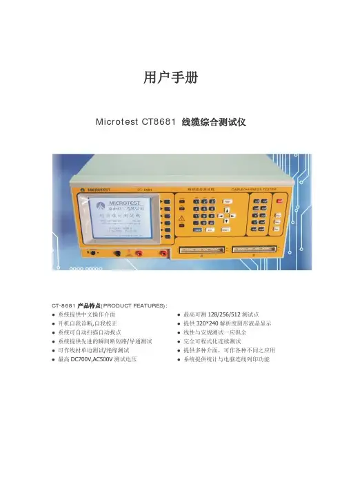
2输出容量大伏安特性试验最大输出电压高达1000V,变比测试最大输出电流高达600A,仪器内置调压器输出容量为5KV A。
3可选配件包括外接升压器,外接升流器,外接调压器,外接升压器最高电压可升至2000V 3A,外接升流器可升至1000A,外接调压器最大输出可达1500V,20A,采用外接升压器时,最高可做500KV等级1A电流互感器的伏安特性试验。
4大屏幕320*240点阵汉字图形界面,测试完成后可直接显示伏安特性曲线图,图形清晰,美观,易于分析,自带微型打印机,可随时打印曲线和测试结果。
5仪器使用旋转鼠标作为输入设备,操作方便简单,使用寿命长。
6仪器内置Flash存储器,数据保存后掉电不丢失,现场试验完成后,可在室内查看和打印试验结果。
7仪器带有RS232通信接口,可以使用串口连接线与计算机联机,实现PC机和仪器通信,试验人员可以通过计算机控制仪器进行试验或从仪器上传试验数据,仪器所带PC机应用程序功能强大,美观大方,操作简单,可实现试验结果的保存、打印,并可将试验数据导出为EXCEL格式文档进行编辑。


目录一、产品概述1二、主要技术特性22.1工作环境22.2电气参数22.3环境温湿度测量范围及测量精度22.4数据通讯22.5触头/电缆搭接头节点测温参数3三、模拟显示及主要功能说明33.1模拟指示部分43.2高压带电显示及闭锁43.3自动加热除湿控制功能53.4分合闸回路电压数值显示53.5分合闸功能53.6验电功能53.7电力参数的测量、显示63.8人体感应探头63.9智能语音防误提示功能63.10动态设置功能63.11转换开关63.12无线温度采集功能63.13告警信息液晶显示功能7四、温度无线传感器安装7五、安装及使用数明:7六、使用说明96.1按键定义介绍:96.2电源接线96.3液晶显示9七、设备指示灯说明15八、SKCD800系列智能操显装置产品选型一览表16九、温湿度传感器接线方式17十、注意事项17十一、产品订购17一、产品概述SKCD800系列装置是根据当前中压系统开关柜技术发展而设计开发的一种新型的模块化、智能型的操作测量显示装置。
该系列产品具有一次动态模拟显示、分合回路完好指示、人体感应探头、高压带电指示及闭锁、温湿度数字实时显示、自动加热除湿控制、自动排风降温控制、断路器分合闸状态指示、储能、接地开关指示、手车位置指示、智能防误语音提示、参数设置、数字显示、验电核相功能、人体感应报警语音警示、带电提示、综合电力参数显示、无线温度采集功能、加热器断线指示报警、智能防误语音提示、自动储能选择、远程就地切换、分闸、合闸操作以及RS485 通讯接口等功能,可根据现场实际情况需要选配。
该产品以一体化布局配套装备于开关柜,将简化开关柜的面板结构设计,美化开关柜的面板布局,完善开关状态的指示功能和安全性能。
广泛用于各行业特别是电力系统中对设备工作环境温湿度要求较高及智能化较高的开关柜中。
二、主要技术特性2.1工作环境温度:-20~+70相对湿度95%RH海拔高度4500m2.2电气参数工作电源:AC 85V~240V / DC220V,频率50/60HZ。
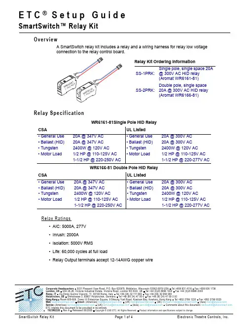
E T C ® S e t u p G u i d eSmartSwitch™ Relay KitOverviewA SmartSwitch relay kit includes a relay and a wiring harness for relay low voltage connection to the relay control board.Relay SpecificationRelay Ratings•AIC: 5000A, 277V •Inrush: 2000A •Isolation: 5000V RMS •Life: 60,000 cycles at full load•Relay Output terminals accept 12-14AWG copper wireWR6161-81Single Pole HID Relayd e t s i L L U AS C • General Use 20A @ 347V AC • General Use 20A @ 300V AC • Ballast (HID)20A @ 347V AC • Ballast (HID)20A @ 300V AC • Tungsten 2400W @ 120V AC • Tungsten 2400W @ 120V AC • Motor Load1/2 HP @ 110-125V AC • Motor Load1/2 HP @ 110-125V AC 1-1/2 HP @ 220-250V AC1-1/2 HP @ 220-277V ACWR6166-81 Double Pole HID Relayd e t s i L L U AS C • General Use 20A @ 347V AC • General Use 20A @ 300V AC • Ballast (HID)20A @ 347V AC • Ballast (HID)20A @ 300V AC • Tungsten 2400W @ 120V AC • Tungsten 2400W @ 120V AC • Motor Load1/2 HP @ 110-125V AC • Motor Load1/2 HP @ 110-125V AC1-1/2 HP @ 220-250V AC1-1/2 HP @ 220-277V ACRelay Kit Ordering InformationSS-1PRK:Single pole, single space 20A@ 300V AC HID relay(Aromat WR6161-81)SS-2PRK:Double pole, single space 20A @ 300V AC HID relay (Aromat WR6166-81)Installation ProcedureStep 1:Remove the cover assembly from the SmartSwitch enclosure to reveal the relay panel interior.a:Step 2:Pull line feeds through conduit from the circuit panel to the relay panel.Step 3:Pull load wires through conduit from the relay panel to the lighting loads.Step 4:If installing one relay remove only one slot from the relay voltage barrier.W A R N I N G :RISK OF ELECTRIC SHOCK! All relay panel maintenance and terminations must be completed with the power removed. All line feeds from the circuit breaker panel must be locked out in the OFF position prior to installing additional relays.N o t e :It is important to separate low voltage from high voltage within the relay panel. SmartSwitch units shipped from the factory only partially populated include a relay voltage barrier in slots not populated with a relay. Remove only the slot from the relay voltage barrier that is to be replaced with a relay.Rough-in enclosure and front for clarity of the relay panel interior.Factory installed relay voltage barrier with removable slots. Remove only one slot whenreplacing with a relay.Step 5:Install the relay into the relay slot.Step 6:Install the keyed two pin connector found on the relay wiring harness into the adjacent receptacle on the relay control board.Step 7:If the relay wiring harness was not attached to the relay upon receipt, connect the wire leads from the wiring harness to the low voltage input terminals on the relay. a:Connect the blue wire to the blue screw terminal and secure. b:Connect the red wire to the red screw terminal and secure.Step 8:Connect line and load wires to the output terminals of the relay.a:Strip 1/4” of insulation from the end of the line and load copper wires. b:Insert the bare-end into the relay output screw terminals and secure.C A U T I O N :Careful not to damage the relay control board or connectors during relayinstallation.Verify Installation•Are all line and load cables landed into the appropriate relay and secured?•Are all load circuits free of shorts?•Are voltage barriers used where required by local code?•Are all cable access openings covered with plugs and all removable plates reinstalled?•Are all relay low voltage (control) wiring harnesses seated properly in the connector and secure to the relay input terminals?•Is the relay panel clean of all metal shavings and debris?•Is the circuit panel schedule updated with the new load information?Power UpStep 1:Switch all relays to the OFF position prior to applying power.Step 2:Re-attach the front cover to the unit.Step 3:Apply power to the control electronics.Step 4:At the circuit breaker panel, switch all line feeds to the ON position.Step 5:Clear all faults that have caused breakers to trip.。

®80T-IR/E Extended Range InfraredTemperature ProbeInstruction SheetIntroductionThe Fluke 80T-IR/E Extended Range Infrared Temperature Probe (the probe) is a noncontact temperature measurement accessory for use with a test instrument capable of measuring DC volts in the millivolt range such as a digital multimeter (DMM). The probe has a temperature range of 32°F to 1000°F, witha basic accuracy of 3% of reading, and an output of 1 mV dc per °F.Temperature is measured by pointing the probe at the surface to be measured, and reading the temperature on the test instrument display.Box ContentsTemperature Probe, Battery (installed), Instruction Sheet, and Warranty Card.Safety InformationThe 80T-IR/E complies with IEC Publication 1010-1-1990 including Amendment 1, CSA C22.2 No. 231, ANSI/ISA-S82.01 and .03 Safety Standards.W WARNINGIF TARGET EMMISSIVITY IS LESS THAN 0.95, THE PROBE CAN INDICATE A TEMPERATURE LOWER THAN THE ACTUAL TARGET TEMPERATURE. AVOID TOUCHING THE TARGET; THERMAL BURNS COULD RESULT.CAUTIONDo not place the probe on or around hot objects (70°C / 158°F). It will damage the probe case.If the probe is exposed to significant changes in ambient temperature (hot to cold or cold to hot), allow 20 minutes for temperature stabilization, before taking measurements.Do not operate the probe near large electrical or magnetic fields such as arc welders and induction heaters. These fields can cause measurement errors.Condensation may form on the lens when going from a cold to hot environment - wait 10 minutes for condensation to dissipate before taking measurements.Connectors must only be plugged into voltage measurement input jacks of the test instruments.Do not touch or hold by the front cone.Temperature readings can be affected by heat from the hand.Equipment use not specified by manufacturer may impair safety.CompatibilityThe probe is compatible with all DC millivolt measuring instruments that have a minimum of 1 M input impedance and accept safety shrouded, standard diameter 0.16 in. (4 mm) banana plugs.OperationTo take a measurement, perform the following steps: 1. Plug the red connector into the V dc input jackand the black connector into the common or ground input jack on the test instrument.2. Select mV dc on the test instrument.3. Slide the probe switch forward to the "ON"position.4. Point the tip of the probe as close as possible tothe object being measured without touching the object.5. Read the test instrument display.Additional considerations are:After 10 minutes of use the probe will automatically shift to Sleep mode (the display will show 0°F). It can be restarted by sliding the switch to "OFF" and then to "ON" (see Table 1).Sleep mode extends battery life. However, for maximum battery life, switch the probe to the "OFF" position.If the test instrument displays an overload condition, switch the DMM range from mV dc to V dc. Increasing the range to V dc moves the decimal position three places to the left (1000°F displays as 1.000V dc).Figure 1.Display CodesUnder the conditions shown in Table 1, the meter will alternate between displaying a reading and Display Code. EmissivityAll objects emit invisible infrared energy. This ability, called emissivity, is based upon the material that the object is made of and its surface finish. Emissivity values typically range from 0.10 for a very reflective object to 0.98 for a near perfect black body. The probe senses this energy assuming that the target has an emissivity value of 0.95. This value is factory set in the probe. If the actual target emissivity is less than 0.95, the indicated temperature could be less than the actual target surface temperature. To correct for this, apply masking tape or a coat of matte paint to the target. The resulting target will have an emissivity of approximately 0.95.Table 1.Display Codes Condition Action1041°F Target temperatureis over range.Select target within probe's specified temperature range.-135°F The temperature ofthe probe is nearthe low ambientoperating rangelimit.**Ensure that the probe is within the specified ambient operating range.-192°F Battery power is low.Replace thebattery.0°F Sleep mode orbattery is dead.Restart the probe by sliding switch to "OFF" and then to "ON", or replace battery.* All values are nominal.** Although a display code may be present, the displayed reading is valid if the probe is within the specified ambient operating range.Distance to Spot Size RatioDistance to Spot Size Ratio (or Field of View) refers to the diameter of the spot that the probe is sensing at a given distance. The closer you are to the object (or target), the smaller the area (or spot) the probe is sensing. For example when the probe is held at a 200 mm (8 in.) distance from the target, the spot size is approximately 50 mm (2 in.); at 100 mm (4 in.) the spot size is approximately 25 mm (1 in.), and with the probe held at a 50 mm (2 in.) distance from the target, the spot size is approximately 13 mm (1/2 in.). Hot spots can be missed if too large an area is included in the field of view, so get as close as possible! (See Figure 2.)hh S p o t s i z e i n c r e a s e s w i t h d i s t a n c e f r o m t h e p r o b e t i p , a s s h o w nFigure 2.Measurement ConsiderationsIf the surface to be measured is small (13 mm (1/2 in.) or less), hold the probe as close as possible to the surface (no more than 50 mm (2 in.) away).If the surface to be measured is covered by frost or other material, clean it to expose the surface.If the surface to be measured is highly reflective such as polished metal, apply masking tape or a matte finish paint to the surface.If the probe seems to be giving incorrect readings check the front of the probe. There may be condensation or debris obstructing the sensor;clean per instructions in the maintenance section. Quick CheckFor a quick check of the probe, point it directly at ice immersed in water (slush), the meter should read, within specifications limits, 32°F (see Accuracy specifications).SpecificationsTemperature Range:32°F to 1000°F Operating Temperature:32°F to 122°FAccuracy for 1 year: (Operating temperature 64°F to 82°F)32°F to 180°F: ±5.4°F >180°F : ±3% of readingTemperature Coefficient:±0.3% of reading or±0.7°F, whichever isgreater, change inaccuracy per 1.8°Fchange in ambientoperating temperatureabove 82°F or below64°F.Response Time: 1 secondSpectral Response:8 to 14 microns nominal Emissivity:pre-set 0.95Output: 1 mV/degree °FRelative Humidity:95% RH or less @ 86°Fnoncondensing, Temp.Coef. appliesStorage Temperature:-13° to 158°F withoutbatteryPower:9V battery; (NEDA1604A, 6F22, 006P) Battery life (Alkaline):50 hours typical, @ 73°F33% duty cycle Dimensions:(L x W x H) 180 mm x30 mm x 50 mm (7.1 in.)x (1.2 in.) x (2 in.) Weight:180 gm (6.4 oz)MaintenanceBattery ReplacementRemove battery door (See Figure 1.) and replace with a 9V Alkaline battery (ANSI/NEDA 1604A, IEC 6LR61). Front-Window Cleaning (as necessary)1. Blow off loose particles using clean compressedair.2. Gently brush remaining debris away with a camelhair brush or Q-tip.3. Carefully wipe the surface with a moist Q-tip. Theswab may be moistened with water or a water-based glass cleaner. Allow to air dry. (Do not usesolvents to clean the window.)Case CleaningTo clean the exterior housing, simply use soap and water or a mild commercial cleaner. Wipe with a damp sponge or soft rag.LIMITED WARRANTY & LIMITATION OF LIABILITY Each Fluke product is warranted to be free from defects in material andworkmanship under normal use and service. The warranty period is one year and begins on the date of shipment. Parts, product repairs, and services are warranted for 90 days. This warranty extends only to the original buyer or end-user customer of a Fluke authorized reseller, and does not apply to fuses, disposable batteries, or to any product which, in Fluke's opinion, has been misused, altered, neglected, contaminated, or damaged by accident or abnormal conditions of operation or handling. Fluke warrants that software will operate substantially in accordance with its functional specifications for 90 days and that it has been properly recorded on non-defective media. Fluke does not warrant that software will be error free or operate without interruption.Fluke authorized resellers shall extend this warranty on new and unused products to end-user customers only but have no authority to extend a greater or different warranty on behalf of Fluke. Warranty support is available only if product is purchased through a Fluke authorized sales outlet or Buyer has paid the applicable international price. Fluke reserves the right to invoice Buyer for importation costs of repair/replacement parts when product purchased in one country is submitted for repair in another country.Fluke's warranty obligation is limited, at Fluke's option, to refund of the purchase price, free of charge repair, or replacement of a defective product which is returned to a Fluke authorized service center within the warranty period.To obtain warranty service, contact your nearest Fluke authorized service center to obtain return authorization information, then send the product to that service center, with a description of the difficulty, postage and insurance prepaid (FOB Destination). Fluke assumes no risk for damage in transit. Following warranty repair, the product will be returned to Buyer, transportation prepaid (FOB Destination). If Fluke determines that failure was caused by neglect, misuse, contamination, alteration, accident, or abnormal condition of operation or handling, including overvoltage failures caused by use outside the product's specified rating, or normal wear and tear of mechanical components, Fluke will provide an estimate of repair costs and obtain authorization before commencing the work. Following repair, the product will be returned to the Buyer transportation prepaid and the Buyer will be billed for the repair and return transportation charges (FOB Shipping Point).THIS WARRANTY IS BUYER?S SOLE AND EXCLUSIVE REMEDY AND IS IN LIEU OF ALL OTHER WARRANTIES, EXPRESS OR IMPLIED, INCLUDING BUT NOT LIMITED TO ANY IMPLIED WARRANTY OF MERCHANTABILITY OR FITNESS FOR A PARTICULAR PURPOSE. FLUKE SHALL NOT BE LIABLE FOR ANY SPECIAL, INDIRECT, INCIDENTAL, OR CONSEQUENTIAL DAMAGES OR LOSSES, INCLUDING LOSS OF DATA, ARISING FROM ANY CAUSE OR THEORY.Since some countries or states do not allow limitation of the term of an implied warranty, or exclusion or limitation of incidental or consequential damages, the limitations and exclusions of this warranty may not apply to every buyer. If any provision of this Warranty is held invalid or unenforceable by a court or other decision-maker of competent jurisdiction, such holding will not affect the validity or enforceability of any other provisionFluke Corporation Fluke Europe B.V.P.O. Box 9090P.O. Box 1186Everett, WA 98206-90905602 BD EindhovenU.S.A.The Netherlands11/99ServiceFor service information in the U.S.A., call 1-800-526-4711. Outside the U.S.A., contact the nearest Fluke Service Center. To locate an authorized service center, visit us on the World Wide Web: or call Fluke using the phone numbers listed below:USA: 1-888-99-FLUKE (1-888-993-5853)Canada: 1-800-36-FLUKE (1-800-363-5853) Europe: +31 402-678-200Japan: +81-3-3434-0181Singapore: +65-738-5655Anywhere in the world: +1-425-446-5500CalibrationFluke recommends that the user return the probe annually to a Fluke Service Center for calibration, starting one year after purchase.Replacement PartBattery (Alkaline) - PN 614487Calibration Procedures - PN 650900PN 601788February 1996 Rev. 3, 4/001993,1994,1996,1997,2000 Fluke Corporation.All rights reserved. Printed in U.S.A.All product names are trademarks of their respective companies.。
GPS车载监控管理终端T80-1/T80C使用说明书广州超前计算机科技有限公司版权所有侵权必究(版本2.0 修改时间20XX-10-13)请先阅读本节◎感谢您购买本公司的产品,在使用产品之前,请认真阅读本说明书,并请遵守本书每一章节的操作和注意事项。
当您开始使用产品时,本公司认为您已经认真地阅读了本说明书。
◎本说明书提供的信息,经仔细核对,务求精准。
如有任何印刷或翻译错误,本公司不承担因此产生的后果。
◎本设备属于高技术产品,本公司在硬件的制造过程和软件的开发以及运用过程中已经尽到了充分的注意义务,以确保产品能够正常工作。
如果产品发生故障,本公司除了根据品质保证规定承担维修责任之处,对于用户因使用本产品而导致的财产损害和经济损失不承担任何赔偿责任。
◎此说明书的所有著作权都归本公司所有,不得随意复制或翻译此说明书的全部或部分进行商业活动,本公司保留对此说明书内容的最终解释权。
◎本设备产品相关参数如有变更,恕不另行通知。
目录一.概述 (1)二.产品主要功能 (1)三.主要功能介绍 (2)3.1重点推荐功能 (2)3.2定位监控功能 (2)3.3报警装置功能 (2)3.4综合管理功能 (2)3.5地图功能 (3)四.GPS定位原理图 (3)五.产品安装与接线 (3)5.1手机卡安装 (3)5.2报警开关安装 (3)5.3现场调试检测 (3)5.4主机接线图 (4)六.包装清单 (4)七.安装注意事项及维护常识 (5)7.1安装注意事项 (5)7.2维护常识 (5)八.主要技术参数 (5)九.故障排除 (5)十.售后服务 (6)一.概述T80系列产品(T80-1/T80C)是由广州超前计算机科技有限公司研发,具有卫星定位、手机查车功能、车辆实时报警、历史行驶轨迹回放及报表分析等功能,可对行驶车辆进行远程监控的车载监控管理终端。
T80系列车载监控管理终端,通过GPS系统提高了对车辆的有效管理,掌握车辆实时位置、行驶速度、里程信息,可对车辆状况进行控制,获得车辆安全信息等,对道路安全运输,预防道路交通事故发生,提高安全管理水平,落实科技兴安战略起到了决定性的作用。