BET-KB智能操控装置说明书
- 格式:pdf
- 大小:427.64 KB
- 文档页数:15
BET-BFK型变压器风冷智能控制柜使用说明书目录一、产品概述 (2)二、引用标准 (2)三、型号说明 (3)四、使用环境条件 (3)五、控制原理及方式 (4)六、功能特点 (5)七、外形与地基安装图 (5)八、订货须知 (6)BET-BFK型变压器风冷智能控制柜·使用说明书一、产品概述电力系统由发电、变电、输电、配电、用电几个环节组成,其中变压器是一个十分重要的元件,它的安全运行对电力系统起着十分重要的作用。
变压器在运行过程中,绕组中的铜耗和铁芯中的铁耗都转变为热能,使变压器各个部分的温度升高,变压器的使用寿命主要由绝缘老化程度决定,绝缘老化主要是由温度变化造成的。
研究结果表明:在超越设计温度情况下,温度每升高6℃,变压器的使用寿命就要减少一半,这便是变压器绝缘老化的六度规则。
由此可见温度是影响变压器使用寿命的一个重要指标。
在110kv、220kv、500kv、1000kv的油浸变压器中,主要采用自然油循环风冷、强迫油循环风冷和强迫油循环水冷三种冷却方式,其中绝大部分采用自然油循环风冷和强迫油循环风冷冷却方式。
变压器风冷智能控制柜就是针对着三种冷却方式而设计的智能型控制柜。
它可以实现远方自动和就地手动控制方式,并可以把各种信息上传显示和下行控制设定,对变压器整个冷却系统实现最优控制,达到节能和延长散热器使用寿命的目的。
二、引用标准GB1094-1996 电力变压器GB2900-1982 电工术语GB2536-1990 变压器油GB/T13499-1992 电力变压器应用导则GB/T17468-1998 电力变压器选用导则JB/T3837-1996 变压器类产品型号编制方法DL/T572-1995 电力变压器运行规程DL/T5147-2001 电力系统安全自动装置设计技术规定GB7621-1981 电气设备额定电流GB/T2682-1981 低压成套装置中的指示灯和按钮颜色BET-BFK 变压器变压器风冷智能控制柜·使用说明书GB 7251-1997 低压成套开关设备和控制设备DL/T 720-2000 电力系统继电保护柜、屏通用技术条件DL/T 5136-2001 火力发电厂、变电所二次接线设计技术规程GB50054-1995 低压配电设计规范三、型号说明型号举例:BET-BFKW12-4/Q 则为北特电气生产的微机型12个风机4组冷却器强油循环风冷智能控制柜。
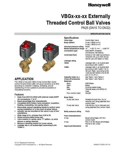
® U.S. Registered TrademarkCopyright © 2015 Honeywell Inc. • All Rights ReservedEN0B-0717GE51 R1115VBGx-xx-xx Externally Threaded Control Ball ValvesPN25 (DN15 TO DN32)SPECIFICATION DATAAPPLICATIONThe VBG2 2-Way and VBG3 3-Way Control Ball Valves control hot and chilled water with glycol solutions up to 50% according to VDI2035 in heating, ventilating, and air conditioning (HVAC) systems to provide two-position or modulating functions.Features∙ Sizes from DN15 to DN32 with external (male) BSPP(G) connections 1" to 2".∙ Equal percentage flow characteristic.∙ Compatible MVN Rotary Valve Actuators: 2-position,floating, modulating, non-spring return.∙ Removable manual operating handle to control valveduring installation or in the event of power failure. ∙ Actuator can be mounted on the valve in any of fourorientations.∙ Wide range of k VS choices from 0.25 to 25. ∙ Nickel-chrome plated brass ball.∙ Valve installs in a globe valve "T" pattern, no extraelbows or piping required.∙ Mixing or diverting control for 3-way valves.∙ Leakage rate A, air bubble-tight (according to EN12266-1).SpecificationsValve type Control Ball Valve Body pattern 2-way (VBG2-xx-xx),3-way (VBG3-xx-xx)Nominal pressure rating PN25Media temperature range +5 … +120 °C (+41 … +248 °F) Connection type Male BSPP, threadedconnections, flat sealingControlled fluid Chilled or hot water according toVDI2035 with up to 50% Glycol. Not for use with steam or fuels.Leakage rating VBG2 Leakage rate A, air bubble-tightaccording to EN 12266-1VGB3 Leakage rate A, air bubble-tightaccording to EN 12266-1 for A-AB port, Rate I according to EN 1349 and EN 60534-4 for B-AB port (0.1% of kV)Capacity index (k vs ) see Table 1 and Table 2 Close-off pressures see Table 1 and Table 2 Materials:Body DZR Brass Stem BrassBall Chrome-plated brass Seat Teflon® seals with EPDM O-rings Flow control insert Noryl®Body Style:2-way ball valve Straight-through flow, full orreduced port using patented flow control insert3-way ball valve A-B-AB flow, full or reduced portusing patented flow control insertBody pressure rating PN25Flow Characteristics: 2-way Equal percentage with flowcontrol insert3-way Port A to AB: Equal percentage;Port B to AB: LinearApprovals/Standards CEVBGx-xx-xx EXT. THREADED CONTROL BALL VALVES PN25 (DN15 TO DN32) – SPECIFICATION DATAEN0B-0717GE51 R1115 2Table 1. VBG2 Two-way control ball valvesDN K vs A-BO.S. no.Close-off pressure with MVNRotary Valve Actuators (kPa)External threadsize150.25 VBG2-15-0.25 890 1"0.4 VBG2-15-0.4 0.63 VBG2-15-0.631 VBG2-15-11.6 VBG2-15-1.62.5 VBG2-15-2.5 4 VBG2-15-4 6.3 VBG2-15-6.3 204 VBG2-20-4890 1 ¼" 6.3 VBG2-20-6.3 8.6 VBG2-20-8.6 256.3 VBG2-25-6.36801 ½"10 VBG2-25-10 16 VBG2-25-16 25 VBG2-25-2532 16 VBG2-32-16 2" 25 VBG2-32-25Table 2. VBG3 Three-way control ball valvesDN k vs A-B k vs B-AB O.S. no.Close-off pressure with MVNRotary Valve Actuators (kPa) External thread size150.63 0.5 VBG3-15-0.63 3401"1 0.8 VBG3-15-11.6 1.28 VBG3-15-1.62.5 2 VBG3-15-2.5 43.2 VBG3-15-4 6.3 5.04 VBG3-15-6.3 204 3.2 VBG3-20-41 ¼" 6.3 5.04 VBG3-20-6.3 8.6 6.88 VBG3-20-8.6 256.3 5.04 VBG3-25-6.31 ½"10 8 VBG3-25-10 16 12.8 VBG3-25-1632 16 12.8 VBG3-32-16 270 2"25 20 VBG3-32-25VBGx-xx-xx EXT. THREADED CONTROL BALL VALVES PN25 (DN15 TO DN32) – SPECIFICATION DATA3 EN0B-0717GE51 R1115V B G 12552BALL VALVEMALE EXT. THREAD2-WAY 3-WAY2:3:25:15:0.25:0.4:0.63:1:1.6:2.5:4:6.3:8.6:10:16:25:DN25DN15Kvs = 0.25Kvs = 0.4Kvs = 0.63Kvs = 1Kvs = 1.6Kvs = 2.5Kvs = 4Kvs = 6.3Kvs = 8.6Kvs = 10Kvs = 16Kvs = 25DN32DN2032:20:Fig. 1. VBG product keyTable 3. Valve accessories and replacement partsPart no.Description5112-19 Replacement stem assembly for VBG, DN15-20 5112-20 Replacement stem assembly for VBG, DN25-32MVNAAAReplacement valve adaptor, standard profile, pre-assembled on the VBG valves AC-15TF-1 Fittings accessories DN15 VBG valves AC-20TF Fittings accessories DN20 VBG valves AC-25TF Fittings accessories DN25 VBG valves AC-32TF Fittings accessories DN32 VBG valvesTable 4. Connection sets ConnectionPipe size DN O.S. no. Connection setDescriptionInternal threadR ½"15 AC-15TF-1Consisting of 1union nut, 1 tail-piece, and 1 gasketR ¾" 20 AC-20TF R 1" 25 AC-25TF R 1-¼"32AC-32TFTable 5. Connection set dimensionsConnection setacO.S. no.G 1" G 1/2" AC-15TF-1 G 1-1/4" G 3/4" AC-20TF G 1-1/2” G 1" AC-25TF G 2” G 1-1/4"AC-32TFVBGx-xx-xx EXT. THREADED CONTROL BALL VALVES PN25 (DN15 TO DN32) – SPECIFICATION DATAEN0B-0717GE51 R1115 4Table 6. VBG2 dimensions (in mm)DNA B C D G H I J K O15 74.0 67.1 19.1 48.0 G1" 92.3 71.0 142.1 123.0 36.0 20 85.5 77.2 24.7 52.7 G1¼" 98.05 71.0 152.2 127.7 46.0 25 84.5 84.1 26.8 57.5 G1½" 97.55 71.0 159.1 132.5 50.0 32 102.0 98.1 36.0 63.4 G2" 106.3 71.0 173.1 138.4 65.0Table 7. VBG3 dimensions (in mm) DNA B C D E G H IJ K O15 74.0 107.1 41.1 49.144.0G1"92.371.0182.1 124.141.020 85.5 109.4 46.9 49.149.5G1¼"98.0571.0184.4 124.146.025 84.5 118.4 44.4 53.153.5G1½"97.5571.0193.4 128.150.032 107.5 142.3 50.9 63.069.0G2"109.0571.0217.3 138.065.0VBGx-xx-xx EXT. THREADED CONTROL BALL VALVES PN25 (DN15 TO DN32) – SPECIFICATION DATA5 EN0B-0717GE51 R1115MountingWhen installing the valve care must be taken that the flow direction is correct (see section "Typical Operation" below). The valve must not be mounted with the stem pointing downward.The valve is supplied complete with mounting instructions. The water quality must meet VDI 2035 requirements. NOTE:Mount the actuator by hand, only. Do not use a tool, as this could result in damageTypical OperationAll types of valves should be mounted in the return flow. If the Dp-values exceed 300 kPa, attention should be paid to the development of noise.Two-Way ValvesDirection of flow always from port A to port BThree-Way ValvesThese valves are used preferably as mixing valves. This means:Port AB: Total flow outlet Port A: Controlled flow inletManufactured for and on behalf of the Environmental and Combustion Controls Division of Honeywell Technologies Sàrl, Rolle, Z.A. La Pièce 16, Switzerland by its Authorized Representative:Automation and Control Solutions Honeywell GmbH Böblinger Strasse 1771101 Schönaich, Germany Phone +49 (0) 7031 637 01 Fax +49 (0) 7031 637 740 EN0B-0717GE51 R1115Subject to change without noticeDISPOSAL OF VBG CONTROLL BALL VALVESOBSERVE LOCAL REQUIREMENTS ON PROPER WASTE RECYCLING / DISPOSAL!∙ Dezincification-resistant brass body ∙ Chrome-plated brass ball∙ Teflon® seals with EPDM O-rings ∙ Noryl® flow control insert。
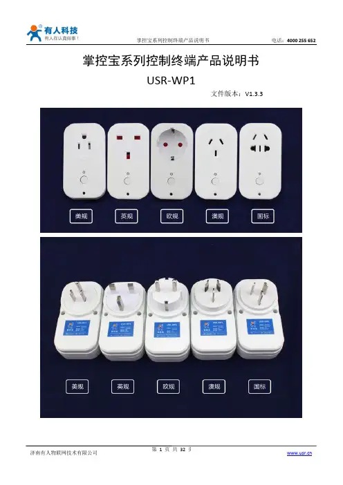
掌控宝系列控制终端产品说明书USR-WP1文件版本:V1.3.3目录掌控宝系列控制终端产品说明书 (1)一、快速入门 (3)1.1直连控制 (3)1.2局域网控制 (6)1.3远程控制 (8)二、产品介绍 (11)2.1产品简介 (11)2.2产品功能特点 (11)2.3数据参数 (11)2.4指示灯和按键功能介绍 (13)2.5Usr-link使用说明 (14)2.6定时使用说明 (14)2.7恢复出厂设置 (15)三、使用说明 (16)3.1上电检测 (16)3.2网络配置 (16)3.2.1Usr-Link配置 (16)3.2.2网页配置 (22)四、掌控宝软件功能介绍 (28)有人联系方式 (32)免责声明 (32)附录版本历史 (32)一、快速入门准备条件:1.将USR-WP1插到电源插座上。
2.安装掌控宝软件到手机IOS、安卓可以直接扫描下方二维码(由于微信不支持扫描下载功能请用UC等软件扫描下载)。
IOS系统也可从App Store中搜索“掌控宝”。
如果需要Windows等版本直接进官方网站选择“资料下载”。
/Download/164.html /Download/163.htmlIOS系统下载链接安卓系统下载链接1.1直连控制1.连入WiFi插座无线网络打开手机设置,在无线局域网中找到USR-WP1,连接至该网络。
点击软件图标,滑到启动界面,点击Start。
进入设备页面,找到USR-WP1,点击USR-WP1栏,进入资源控制页面。
4.基本控制操作此时就可以控制USR-WP1进行各种操作了。
点击输出口后面的开关按钮,就可以打开、关闭各路输出。
也可以锁定输出,对输出进行定时,用户可以简单体验一下,后面会有详细介绍。
1.2局域网控制1.WiFi插座工作在AP模式下(相当于WiFi插座有WiFi信号),打开手机设置页面,在WLAN选择USR-WP1网络,手机连接成功后,WiFi插座的指示灯变成蓝色,代表网络连接成功。

技术手册BeTrac 1 AGVBerg HortimotiveBurg.Crezeelaan 42a2678 KZ De LierThe Netherlands电话:+31 (0) 174- 517 700电子邮箱:************************网站:第7版,2019十月机器制造商:Berg HortimotiveBurg.Crezeelaan 42a2678 KZ De LierThe Netherlands电话:+31 (0) 174- 517 700电子邮箱:************************网站:1 声明1.1 版权Berg HortimotiveDe Lier,2019年未经在荷兰De Lier注册的Berg Hortimotive的事先书面同意,本出版物的任何部分均不得以印刷、影印、拍摄或其他方式转载和/或出版。
例外情况包括本来就用于转载的文档部分,例如机器本身的简略说明和规格。
1.2 责任如果忽略BeTrac 1 AGV上所示的或本文档中所含的警告或说明,导致发生危险情况、事故或损害,Berg Hortimotive概不承担责任,疏忽情况举例如下:- 缺乏经验的或不正确的使用或维护- 使用范围超出设计使用范围,或者使用情形超出本文档给定的情形- 使用未规定的组件或备件- 未经Berg Hortimotive和/或认证经销商的同意便进行维修- 对BeTrac 1 AGV进行改造。
这包括:- 更改控件- 焊接、机械加工等- 扩展BeTrac 1 AGV或其控件- 改变路线或加工线。
在以下情况下,Berg Hortimotive概不承担责任:- 客户并未履行与Berg Hortimotive相关的义务(财务或其他方面)- 相应损害是由于BeTrac 1 AGV和/或路线控件的缺陷造成的,例如业务中断、延误等。
1.3 保修在交付后6个月内,对于正常使用过程中发生的材料和制造缺陷,Berg Hortimotive为客户提供保修。

K B6000Ⅲ气体报警控制器使用说明书Ver:HW100602197河南汉威电子股份有限公司HENAN HANWEI ELECTRONICS CO., LTDISO9001认证企业感谢您使用汉威电子系列产品,当您准备使用本产品时请务必仔细阅读本说明。
并按照所提供的有关操作步骤进行,使您能充分享受我公司提供的服务,同时避免您的误操作而损坏本机或发生其它意外。
请妥善保管本手册,以便在您日后需要时能及时查阅、获得帮助。
版权声明本手册版权属河南汉威电子股份有限公司所有,未经书面许可,本手册任何部分不得复制、翻译、存储于数据库或检索系统内,也不可以电子、翻拍、录音等任何手段及方式进行传播。
河南汉威电子股份有限公司秉承科技进步原则,不断致力于产品改进、提高产品性能,公司保留任何产品改进而不预先通知的权利。
如果用户不依照本手册说明擅自安装或修理更换部件,由此产生的责任由用户负责。
产品及产品颜色、款式请以购买的实物为准。
用户服务指引:1在使用本产品前,请根据产品出厂清单仔细核对附件、产品合格证及用户保修卡是否齐全,若发现不全,请立即与销售商或厂家联络。
2本产品自售出之日起十二个月内,凡用户遵守贮存、运输及使用要求,而产品质量低于技术指标的,凭保修单享受免费维修。
3因违反操作规定和要求而造成的损坏、非我公司指定的特约技术服务部维修引起的故障或由于不可抗拒因素引起的产品质量问题,我公司将进行收费维修。
4产品进行维修时,请主动出示产品保修卡。
不能出示产品保修卡的将作为收费维修。
5产品维护、维修后,请出示本手册,维修人员将填写所附的《维护、维修情况记录》并签名;同时也请您在维修人员的《维护、维修情况记录》上签名确认维护、维修内容并提出宝贵意见,如果是单位用户,请加盖公章。
6如果您对我们提供的产品和服务有任何疑问或不满,包括产品技术、质量、安装维修、服务态度、收费标准等问题,请您及时联络我们,我们将会对您的意见妥善处理。
PP41型壁厚控制器使用说明书贝加莱工业自动化(上海)有限公司目录系统特性简介 (3)1系统特性介绍 (3)2控制系统各部件介绍 (4)2.1控制操作面板 (4)2.1.1 面板 42.1.2 接口 52.1.3 性能 62.1.4 安装 62.2功能按键及指示灯 (7)2.3控制器及接线 (9)2.3.1AI351 (9)2.3.2 Am351 (10)2.3.3 PP41自带输入 (10)2.3.4 PP41自带输出 (11)3画面操作说明 (12)3.1登陆画面 (12)3.2连续式型胚曲线设定画面 (12)3.2.1 操作按钮 (12)3.2.2 输入参数 (13)3.2.3 输出参数 (14)3.2.4 插入与删除设定数值点 (14)3.2.5 微调设定数值点间的曲线单元 (15)3.3储料式型胚曲线设定画面 (17)3.3.1 操作按钮 (17)3.3.2 输入参数 (18)3.3.3 输出参数 (19)3.4曲线跟踪画面 (19)3.5标记画面 (20)3.6存储画面 (20)3.7文件改名画面 (21)3.8参数存储画面 (21)3.9文件调出画面 (22)3.10监控画面 (22)3.11数据1(曲线点)画面 (22)3.12数据2画面 (23)3.13初始设定画面 (23)3.13.1 输入参数 (23)3.13.2 模式转换 (24)3.14型芯设定画面 (24)3.14.1 输入参数 (24)3.14.2 输出参数 (25)3.14.3 手动调校 (25)3.14.4 自动调校 (25)3.14.5 调校提示: (25)3.15储料设定画面 (26)3.15.1 输出参数 (26)3.15.2 手动调校 (26)3.16增益设定画面 (26)3.16.1 按钮 273.16.2 输入参数 (27)3.16.3 输出参数 (27)3.17时间设定画面 (27)3.17.1 输入参数 (27)3.17.2 输出参数 (27)3.18中英文切换画面 (28)4机器操作说明 (29)4.1开机步骤 (29)4.2系统参数设定 (29)4.2.1 初始设定 (29)4.2.2 型芯设定 (29)4.2.3 储料设定 (29)5故障处理 (30)5.1故障对应 (30)5.2干扰处理 (30)6电源 (30)7附件 (30)系统特性简介1 系统特性介绍这是一款50点型坯壁厚控制器,用来控制中空成型机型坯的壁厚。
百特智能数显表说明书欧阳歌谷(2021.02.01)工作状态下按SET显示LOCY→按SET输入密码18→按SET显示RAN9→按SET通过△▽选择分度号→按SET显示Poin 设置小数点→按SET显示r9.00设置量程下限→按SET显示r9.FS 设置量程上限工作状态下按SET→通过△▽选择COrr按SET显示old.1→按SET通过△▽修正温度值参数设定说明:Locy:菜单上锁操作入口;按SET键确认;按△▽键退出;开锁密码为18Ran9.:分度号和量程设置入口;按SET键确认;按△▽键退出010/…/y:分度号设置;按△▽键设置;按SET确认PoIn:小数点位置设置;按△▽键设置;按SET确认R9.00:量程零点设置;按△▽键设置;按SET确认R9.FS:量程满度设置;按△▽键设置;按SET确认Corr:量程迁移和滤波时间设置菜单入口;按SET键确认;按△▽键取消Old.1:修正温度值;按△▽键设置;按SET确认按键说明:△:变更参数设定时,用于增加数值SET:参数设定确认键▽:变更参数设定时,用于减少数值常见故障处理:仪表通电不亮:供电电源未接入,正确接入仪表电源;接触不良,取出表芯确认弹片接触是否良好。
LED屏显示:broy分度号选择错,选择与输入信号相符的分度号;输入信号太大,调节与输入信号保证在仪表范围内;信号短线,正确接入信号线。
H.oFL.分度号选择错,选择与输入信号相符的分度号;输入信号太大,调节与输入信号保证在仪表范围内;仪表标定错误,选择正确标定信号重新标定。
L.Ofl.:选择与输入信号相符的分度号;输入信号太小,调节与输入信号保证在仪表范围内;仪表标定错误,选择正确标定信号重新标定昌辉SWP系列智能仪表说明书控制方式:1、正确的接线仪表卡入表盘后,请参照仪表随机接线图接妥输入、输入及电源线,并请确认无误。
2、仪表的上电本仪表与电源开关,接入电源即进入工作状态。
3、仪表设备号及版本号的显示仪表在投入电源后,可立即确认仪表设备号及版本号。
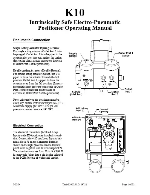
K10Intrinsically Safe Electro-Pneumatic Positioner Operating ManualPneumatic ConnectionSingle Acting Actuator (Spring Return):For single acting actuators Outlet Port 2 is to be plugged. Outlet Port 1 is to be piped to the actuator inlet port that acts against the spring. (Increasing signal causes pressure to increase in Outlet Port 1 of the positioner).Double Acting Actuator (Double Return):For double acting actuators Outlet Port 2 is piped to drive the actuator towards the fail position. Outlet Port 1 is piped to drive the actuator away from the fail position. (Increas-ing signal causes pressure to increase in Outlet Port 1 of the positioner and pressure to decrease in Outlet Port 2 of the positioner).Note: Air supply to the positioner must beMaximum supply pressure is 120 psi. All pneumatic connections are 1/4” NPT.Electrical ConnectionThe electrical connection (4-20 mA Loop Input) to the K10 positioner is polarity sensi-tive. Connect the 4-20 mA Loop Input to ter-minal block J1 on the Connector Board as shown on the right (Positive lead to terminal point 3 and negative lead to terminal point 2). The wire size can range from 20 to 14 AWG is removable (plugs into a pin header soldered to the PCB) for ease of wiring and service.Outlet Port 1GaugeSupply Gauge Outlet Port 1Outlet Port 2Supply (Inlet Port)Position Sensor Initial Angle (Setting Mode)The K10’s Position Sensor, which measures the absolute position of the valve, has a limited operating angle for proper position measurement. The Position Sensor must remain within the operating angle in both the open and fail valve positions. This is accomplished by initially setting the Position Sensor angle while the valve is in the fail position. The K10 has a mode of operation to accomplish the setting of this initial angle using the following steps.1.Apply loop current to the positioner and adjust to12 mA.the actuator is driven to span position. Releaseboth buttons to remove air pressure from OutletPort 1.3. If the valve fails clockwise and strokes counter-clockwise, then set switch SW1 to the CCWposition. If the valve fails counter-clockwise andstrokes clockwise, then set switch SW1 to theCW position (see figure to right).4.With no buttons pressed and the actuator in thefail position, push the Main Shaft Gear (larger ofthe two) down until it disengages from its shaftlocking position.5.Rotate the Main Shaft Gear (both gears willturn), until only the green LED is flashing.Note: If the LED is already green, skip 5 and go to 6.6.Pull up the Main Shaft Gear allowing it to re-engage on the shaft locking it into position.7.Press and hold the High Calibration button untilthe valve fully strokes away from the fail positionwhile watching the LED’s. The red or yellowLED’s must not light as long as the High Cal but-ton is being held down. If the red or yellow LEDlights while the High Cal button is being helddown, then the Position Sensor Orientation andActuator air piping are out of phase. Correct thephase error by changing the position of SW1 andrepeat this procedure starting from step 2.8.Release the High Calibration button and watch the red LED. The red LED will flash until the valve reaches the fail posi-tion.9.Press the Low Calibration button to exit the Position Sensor Setting Mode (if no buttons are pushed then this mode willtime out automatically in about 2 minutes).Calibrating The K10 PositionerOnce the K10 and actuator have been connected and the initial angle has been set. Low and High Calibration can be performed on the K10. Low Calibration refers to the input current value that drives the valve into the fail position. High Calibration refers to the input current value that drives the valve into the Span Position. Calibration adjusts parameters internal to the K10 that are specific to the actuator, and input current values. The parameters that are adjusted are, the Gain of the K10 servo loop. the end position (Zero/Span) of the valve travel, and Drop-Off point (input current level at which the transducer is forced to the extreme position, to insure that the valve is fully open or closed). The calibration routine uses the input current value to set it’s internal adjustment, so it is important that the input current does not change during the calibration routine.To Do a Low Calibration: (Zero Position)1.Set the Input Current level to the value that drives the valve into the fail position (typically 4 mA).2.Start the Low Calibration routine by pressing and holding the LOW CAL button on the K10 until the Yel-low LED flashes or by pressing the LOW button on the IR Remote (may require security code entry).3.Observe the flashing Yellow LED on the K10 which denotes the various stages of the calibration routine:a.) Flashing 1 time indicates Zero position set routine.b.) Flashing 2 times indicates Transducer Self Calibration routine.c.) Flashing 3 times indicates Gain setting routine.4.When the Green LED begins to flash the Calibration is completed. If the Red LED flashes this is an indica-tion that one of the Calibration routines could not be completed. The number of Red LED flashes indicates the calibration routine that failed.To Do a High Calibration: (Span Position)1.Set the Input Current level to the value that drives the valve into the span position (typically 20 mA).2.Start the High Calibration routine by pressing and holding the HIGH CAL button on the K10 until the Yel-low LED flashes or by pressing the HIGH button on the IR Remote (may require security code entry).3.Observe the flashing Yellow LED on the K10 which denotes the various stages of the calibration routine:a.) Flashing 1 time indicates Span position set routine.b.) Flashing 2 times indicates Transducer Self Calibration routine.c.) Flashing 3 times indicates Gain setting routine.4.When the Green LED begins to flash the Calibration is completed. If the Red LED flashes this isan indication that one of the Calibration routines could not be completed. The number of Red LED flashes indicates the calibration routine that failed.Calibration Complete:******Note: For split range enter desired input values during low & high calibration.Advanced FunctionsThe K10 has the ability to change the calibration settings (Gain, Zero, Span, and Drop-Off) manually. This function was intended to make minor changes in the calibration values after doing the Low and High calibration. Some examples where this might be used are decreasing the Gain if the valve still shows some overshoot on rapid position changes, or increasing the High Drop-Off point so it will not be in effect at 20mA. Exercise caution if using the manual calibration, mis-adjustment of these settings on the K10 positioner can result in erratic behav-ior or failure of operation, and may require resetting the EEPROM before auto-calibration can be performed again.To Do a Manual Calibration Adjustment:Before performing a Manual Calibration Adjustment the positioner needs to be calibrated as described previ-ously.1.Apply Input Current to the K10.2.Start the Manual Calibration routine by pressing and holding the Function (center) button on the K10 untilthe Green and Yellow LED flashes.3.Observe the flashing Green and Yellow LED on the K10 which denotes the various stages of the manualcalibration routine, pressing the Function (center) button again advances to the next stage:a.) Flashing 2 time indicates Manual Gain adjustment.b.) Flashing 4 times indicates Low Drop-Off adjustment.c.) Flashing 3 times indicates Zero position adjustment.d.) Flashing 6 times indicates High Drop-Off adjustment.e.) Flashing 5 times indicates Span position adjustment.4. To alter any characteristics of the positioner follow the following steps:a.) Manual gain Increase the positioner gain by pressing and holding the High Cal button. Decrease thePositioner gain by pressing and holding the Low Cal button. The maximum adjust-ment has been achieved when the red LED lights.b.) Low Drop-Off Increase the mA input signal that the positioner drops output port 1 pressure by press-ing the High Cal button. Decrease the mA input signal that the positioner drops outputport 1 pressure by pressing the Low Cal button.c.) Zero position[To adjust the zero position to a point other than the hard stop of the valve the Lowcalibration of the positioner must have been performed at a current slightly lower thanthe zero position current. (Ex. If the zero position current is 4.0 mA the Low Calibra-tion as described in the previous section needs to be performed at 3.9 mA.)]Increase the zero position by pressing and holding the High Cal button. Decrease thezero position by pressing and holding the Low Cal button. Continue to increase ordecrease the zero position by repeatedly pressing and holding the buttons.d.) High Drop-off Decrease the mA input signal that the positioner drops output port 2 pressure bypressing and holding the Low Cal button. Increase the mA Input signal that the posi-tioner drops output port 2 pressure by pressing the High Cal button.e.) Span Position [To adjust the span position to a point other than the hard stop of the valve the Highcalibration of the positioner must have been performed at a current slightly higherthan the span position current. (Ex. If the span position current is 20.0 mA the Highcalibration as described in the previous section needs to be performed at 20.1 mA.)]Decrease the span position by pressing and holding the Low Cal button. Increase thespan position by pressing the High Cal button.5. The Input Current can be changed during the test to observe the adjustment effects on the K10 behavior.6. To save the adjustments and exit the Manual Calibration Mode the Function (center) button must be heldfor approximately 5 seconds (green and yellow flashing LED’s will change to flash just green when adjust-ments are saved) This procedure to save and exit can be performed from any stage during the Manual Cal-ibration.7. Pressing the Function (Center) button during the High Drop-Off adjustment exits the Manual CalibrationMode without saving any adjustments made.The (IR) Remote Control With The PositionerThe positioner has the ability to be operated (calibrated) via an Infrared (IR) Remote Control. The posi-tioner can be calibrated by using the buttons on the positioner module, however this requires the removal of the top cover. With the (IR) Remote Control the positioner can be calibrated without the removal of the top cover. If the 4-20 mA input current connected to the positioner is not available or the Position Sensor Initial Angle must be set then the removal of the top cover is required. Although the posi-tioner is configured for use with the remote, the (IR) Remote Control is not provided with the positioner. The (IR) Remote Control is an option and must be purchased separately.Programing The IR Remote ControlThe IR Remote Control is programmed at the factory and should not need to be programed again, unless the batteries are removed for an extended period of time (greater than 10 min-utes). To program the IR Remote press the “P1” button then press and hold the “P” button until the red LED blinks twice, then press “0”, “0”, “8”, “1” after which the red LED on the IR Remote blinks twice to confirm the entry. Press the “P2” button then press and hold the “P” button until the red LED blinks twice, then press “0”, “0”, “5”, “4” after which the red LED blinks twice to con-firm the entry.Using The IR Remote ControlThe positioner has two operating modes when using the IR Remote.In the first mode, the positioner will immediately act upon commands from the IR Remote (this can be used when the positioner being calibrated is the only one that will be within range of the IR Remote sig-nal, such as one positioner in a closed room). This mode is enabled by setting the positioner DIP switch position 2 (the one closest to the Low Cal Button) to the “ON” position (away from the LED’s).In the second mode, the positioner will not act upon commands from the IR Remote until a 3 digit secu-rity code is entered (this can be used when there are multiple positioner’s within range of the IR Remote signal). This mode is enabled by setting the positioner DIP switch position 2 (the one closest to the Low Cal button) to the “OFF” position (toward the LED’s). Once the correct code is entered (3 digits followed by the ENTER button) the positioner is enabled to act upon IR Remote commands for 5 minutes. The IR Command Enable time counts down to zero, or is set to zero (positioner no longer acts upon commands) when the positioner gets an ENTER from the IR Remote, that was not preceded by the correct 3 digit security code.“D”P1P2+-HIGHLOWGAINDROP-OFF MANUALBACUNDOEXITPROGRAMING BUTTON BACKLIGHT BUTTON RED LEDMODE BUTTONSHIGH CALIBRATE BUTTONLOW CALIBRATE BUTTONNUMERIC BUTTONSENTER BUTTONUSED FOR THE INITIAL SETUP OF THE IR REMOTETURNS THE IR REMOTE BACKLIGHT ON AND OFF LIGHTS WHEN IR SIGNAL IS BEING SENTENABLES ONE OF THE TWO MODES, WHICHREMAINS IN EFFECT UNTIL ANOTHER ONE OF THESE BUTTONS IS PRESSED. P2 MODE IS THE ONE USED FOR THE POSITIONER.USED TO BEGIN THE HIGH CALIBRATE ROUTINEUSED TO BEGIN THE LOW CALIBRATE ROUTINEUSED TO SELECT THE 3 DIGIT CODE FOR THE POSITIONER SECURITY ADDRESSUSED TO ENTER THE 3 DIGIT CODE FOR THE POSITIONER SECURITY ADDRESSTHE IR REMOTE CONTROL BUTTONSSetting The Positioner Security CodeThe security code is initially set by entering a 3 digit code, while the positioner is in the “Position Sensor Initial Angle” setup mode. To set a security code enter “Position Sensor Initial Angle” setup mode, by pressing and holding the High and Low Calibration buttons on the positioner until the Yellow and Green LED’s flash. Press the 3 digits for the security code on the IR Remote then press the ENTER button on the IR Remote (entering the code too quickly may prevent the positioner from reading it correctly, pause at least 1/2 second between each button pressed and hold each button down for at least 1/2 second on the IR Remote). When the Low Calibration button on the positioner is pressed to exit the “Position Sensor Initial Angle” setup mode the 3 digit security code is stored in the EEPROM and will remain there even if power is removed. Make sure that the security code you assign is different for each of the positioner’s in the area.Resetting the EEPROM Back to FactoryDefault ValuesThe positioner has an internal Electrically Erasable Programmable Read Only Memory (EEPROM)that is used to store the calibration values and the IR Remote security code. These values remain in the EEPROM memory even if power is removed from the positioner. During normal operation of the posi-tioner the EEPROM will not have to be reset. The memory may become corrupted if power to the posi-tioner is lost while the positioner is writing to the EEPROM. which only happens at the very end of the calibration cycle or at the end of the Position Sensor Initial Angle setup. This memory can be reset back to factory default values by holding down the HIgh Cal button while the positioner is being powered up. After the EEPROM is reset, the positioner will have to be calibrated again and the IR Remote security code will have to be set again.Reversing the 4mA and 20mA Positions (Reverse Acting)Normally 4mA of input current represents the closed valve position and 20mA represents the open valve position. The positioner has the option to switch this so 20mA represents the closed valve position and 4mA represents the open valve position. The normal mode is chosen by setting the positioner DIP Switch position 1 (the one closest to the LED’s) to the “OFF” position (toward the LED’s). The reverse acting mode is chosen by setting the positioner DIP switch position 1 to the “ON” position (away from the LED’s). The positioner should be calibrated again any time the switch position is changed.Setting the Switches1.Operate the actuator to one extreme. Choose the switch you would like to signal this position (upperor lower switch). Disengage the appropriate switch cam from the spline by pushing or pulling against the spring (push down for the upper switch, lift up for the lower switch).2.Turn the cam until the switch is activated. Activation of the switch can be monitored using a continuitytester or equivalent means.3. Release the cam allowing it to re-engage with the spline.4. Operate the actuator to the opposite extreme and repeat steps 1 through 3 for the other switch.Wiring SchematicTOP CAMPUSH DOWNTURN & RELEASEBOTTOM CAMLIFT UPTURN & RELEASETOP CAMPUSH DOWNTURN & RELEASESWITCH#1UPPERNCNOCBROWNPURPLEYELLOW123456REDBLUEORANGECNONCSWITCH#2LOWERGNDParts List673521OptionalMechanical SwitchAssembly8*Item #Description1Housing Ass’y Qty 23456111111Shaft Ass’y Electronic Ass’y Transmitter (optional)Manifold Ass’y Motor Ass’y71Connector Board Ass’y81Mechanical Switch Ass’y (optional)*Void FM approval as Non-Incendive when ordered with 2-SPDT switch option .K10 product with optional switches is for use in general purpose applications only.J141Technical DataInput Current 4 to 20 mA (Analog)Voltage Drop 9 voltsSupply Air Pressure (low) Resolution 0.5% of span Linearity ±1% of spanConduit 1 x 3/4” NPTEntriesHousing Engineered Resin (Nylon)Cover Clear Engineered Resin (Nylon)Shaft Stainless Steel Fasteners Stainless Steel HiVue Copolyester Electrical Version SPDT form CElectrical Rating15 Amps @ 125/250 VAC 10 Amps @ 24 VDC 0.5 Amps @ 125 VDC 0.25 Amps @ 250 VDC(high) 15 to 45 psi40 to 120 psi Hysteresis 0.4% of span Repeatability 0.4% of span Thermal Coefficient 3%/100°COutput Flow Rates 8.0 scfm @ 25 psi 16.2 scfm @ 90 psi Air Consumption .30 scfm @ 25 psi .71 scfm @ 90 psiOperating Temp. Range -40°C to 85°C (-40°F to 185°F) GainElectrically Adjustable Air Connection Ports1/4” NPTModMountEngineered Resin (Nylon)Manifold Anodized Aluminum F MAPPROVEDNon-IncendiveClass I, Div 2 Grps A,B,C,D Class II, Div 2 Grps F ,G Class III, Div 2*Void FM approval as Non-Incendive when ordered with 2-SPDT switch option .K10 product with optional switches is for use in general purpose applications only.***DimensionsAppendix AElectro-Pneumatic PositionerTransmitter Calibration Procedure1.Calibrate the Positioner per the operating manual provided with the product.2. Stroke the valve to the fully clockwise extreme.3.Depress the main shaft gear disengaging it from its locking position, take extreme care Not to Turn the main shaftgear, as this will take the positioner out of calibration.4.With the main shaft gear depressed turn the transmitter gear to the fully counter clockwise position, and note thereading (mA) of the transmitter. Next, turn the transmitter gear clockwise until the transmitter changes no more then0.5 mA from previous reading.5.Turn the clockwise mA adjustment screw to adjust the transmitter reading to the desired output for this valve posi-tion (typically this is 4 mA or 20 mA).6.Stroke the valve to the fully counter clockwise extreme.7.Turn the counter clockwise mA adjustment screw to adjust the transmitter reading to the desired output for thisvalve position.8.Stroke the valve between the full clockwise and counter-clockwise positions checking and readjusting the (mA) out-put as necessary.J1CWCCW Main ShaftMain Shaft Gear mA Adjustment ScrewTransmitter Gear mA AdjustmentTransmitter{OutputTerminals 1 & 2(Not Polarity Dependent)for clockwise positionScrew for counter-clockwise position。
BN-KB5604RM遥控键盘使用说明书一、安装方法把云台或智能球的RS485线连接到无线接收盒的RS485接口,把直流12伏电源连接到无线接收盒电源接口。
接通电源,无线接收盒LED显示屏会显示A001或P001,A代表地址码,P代表预置位,001代表1号地址码或预置位。
二、操作方法:1. 输入摄像机地址按代表了摄像机所对应的地址码。
注意:3位数。
说明:无论在何种模式下,按2. 设置预置位按住3秒,这时屏幕显示SET-,输入一个数字,然后按(如果想输入3. 删除预置位按住3秒,这时屏幕显示(如果想输入4. 调用预置位按一些特殊预置位,在输入预置位编号后还需要按ENTER键确认后才能调用。
)5. 其它设置:可以参考1-3项说明来设置(或删除、调用)归位点、归位点等待时间、左限位点、右限位点、自动扫描等等操作。
6. 按键功能介绍1) 上、下、左、右:用于控制云台摄像机的转动2) ENTER:云台转动停止键,当输入数字时是确认键。
3) 0-9:用来输入数字4) C:数字删除键5) -/--:实现在多位数与一位数之间切换,在一位数模式下只能输入0-9,在多位数模式下,可以输入0-255。
6) ESC:无论在何种模式下,当你按ESC键,系统会自动切换到地址输入模式。
7) CAM:进入摄像机地址码输入模式,此模式下可以切换不同摄像机地址码8) SHOT:进入摄像机预置位操作模式,此模式下可以调用预置位9)HOME:调用归位点快捷键A:调用左限位点快捷键B:调用右限位点快捷键P1-P8:1号到8号预置位快捷键10) PRESET:设置预置位,需要按住3秒以上(用法参考前文)11) DELETE:删除预置位,需要按住3秒以上(用法参考前文)12) AUTO:自动扫描快捷键13) SPEED:设置转动速度14) S1-S4:云台转动速度快捷键,S1 =8度/秒,S2=40度/秒,S3=51度/秒,S4=63度/秒15) FOCUS+:聚焦+,FOCUS-:聚焦-16) OPEN:光圈+,CLOSE:光圈-17) ZOOM+:焦距+,ZOOM-:焦距-18) PATTERN:开始/停止学习模式19) RUN:运行一个模式20) DISP:显示软件版本21) F1-F14:用户自定义快捷键22) SETUP:设置协议和波特率,按住3。
佰特变送器按键操作方法
佰特变送器按键操作方法如下:
1. 按下电源开关,启动变送器;
2. 使用向上和向下箭头键调整频道;
3. 使用左右箭头键调整音量;
4. 按下确认键以确定所选的频道和音量设置;
5. 按下静音键可将音量静音;
6. 按下菜单键可进入设置菜单进行更多高级设置;
7. 按下退出键可退出设置菜单或返回上一级菜单。
根据不同型号的佰特变送器,按键操作方法可能会有些许区别,建议在使用前查阅相关的使用说明书以获取更详细的操作指南。
ABBK-TEKMT5000液位计中文操作说明书4.0调试4.1显示操作MT5000发射机设计用一个简单的易于遵循的设置菜单。
本单元操作,至少,基本设置菜单中的项目必须输入。
如果需要进一步设置,可以使用快速校准或额外的菜单项需要进入。
4.1显示操作当电源应用于一个MT5000系列发射机,显示将点亮一个标题屏幕显示模型类型和软件修改。
(图4)这个初始启动周期将持续3秒和当前发射机的输出将在4.00 mA。
在最初的启动周期之后,显示将会改变显示测量水平和当前的输出。
的对应的输出也将转移到当前的水平。
(图5)按下向上或向下的按钮,主要显示可以滚动显示的比例的水平校准范围(图6)或在一个线性化/上测量。
(图7)。
4.1.1。
跳线设置跳开关位于表面上的电子模块,可以建立如下(图8)。
报警(左跳投)把跳投到更低的位置引起的输出去21.00马当有损失或发射机故障信号。
把跳投到上面的位置引起的输出去3.62马当有损失或发射机故障信号。
报警输出作品结合报警延迟设置mA输出菜单中可用。
输出会去报警状态只有一个至少持续的信号丢失报警的持续时间写保护(右跳投)跨接在较低位置时发射机配置不能改变手动或通过哈特?沟通。
(图8)。
把跳投在上层位置允许的配置参数被改变手动或通过哈特?沟通。
(图8)。
4.1.2。
按钮三个按钮位于较低的部分模块的面板(图8)。
将使用这些按钮通过设置和配置菜单导航MT5000。
一些操作需要的按钮一起使用或持有一段时间影响的变化4.3基本设置基本设置的菜单项用于适应MT5000的内部设置一个特定的应用程序。
某些字段需要输入项目和需要设备的正确操作。
其他入境物品不用于发射机的设置并列为可选的。
至少,在基本设置菜单中需要的物品输入MT5000操作。
基本设置菜单项包括调查类型、探针长度和安装类型。
4.3.1。
单位该函数将允许用户选择的单位测量的过程变量所有的单位,并提供一个基础设置功能。
可选择的工程单位包括:英寸、英尺、米,毫米,厘米。
B6500S-290-250•ApplicationStainless Steel Ball and StemTechnical dataFunctional dataValve Size 5" [125]Fluidchilled or hot water, up to 60% glycol Fluid Temp Range (water)0...250°F [-18...120°C]Body Pressure Rating ANSI Class 250, raised-face Close-off pressure ∆ps 310 psiFlow characteristic equal percentage Servicingmaintenance-free Maximum differential pressure (water)50 psi [345 kPa]Flow Pattern 2-way Leakage rate0% for A – AB Controllable flow range 75°Cv 290 ANSI Class250Body pressure rating note raised-faceCv Flow RatingA-port: as stated in chart B-port: 70% of A – AB Cv MaterialsValve body Cast iron - GG 25Stem seal EPDM (lubricated)SeatPTFE Pipe connection 250 lb flanged O-ring EPDM (lubricated)Ballstainless steel Suitable actuatorsNon-Spring GRB(X)Electronic fail-safeGKRB(X)Safety notesWARNING: This product can expose you to lead which is known to the State of California to cause cancer and reproductive harm. For more information go to Product featuresThis valve is typically used in air handling units on heating or cooling coils, and fan coil unit heating or cooling coils. Some other common applications include Unit Ventilators, VAV box re-heat coils and bypass loops. This valve is suitable for use in a hydronic system with variable flow.B6500S-290-250 Flow/Mounting detailsDimensionsDimensional drawingsGRB, GRXA B C D E F G I Number of Bolt Holes13.3" [338]10.3" [262]14.4" [366]9.4" [239]5.5" [140]5.5" [140]9.3" [235]0.9" [22]8GKRB, GKRXA B C D E F G I Number of Bolt Holes13.5" [343]10.3" [262]14.4" [366]9.7" [246]5.5" [140]5.5" [140]9.3" [235]0.9" [22]8GRX, GKRXA B C D E F G I Number of Bolt Holes17.5" [444]10.3" [262]17.0" [433]13.6" [345]5.5" [140]5.5" [140]9.3" [235]0.9" [22]8GRX, GKRXA B C D E F G I Number of Bolt Holes17.5" [444]10.3" [262]17.0" [433]13.6" [345]5.5" [140]5.5" [140]9.3" [235]0.9" [22]8GKRX24-MFTModulating, Electronic Fail-Safe, 24 V, Multi-Function Technology®Technical dataElectrical data Nominal voltage AC/DC 24 VNominal voltage frequency50/60 HzPower consumption in operation12 WPower consumption in rest position 3 WTransformer sizing21 VA (class 2 power source)Electrical Connection18 GA plenum cable, 3 ft [1 m], with 1/2" conduitconnector (10 ft [3 m] and 15 ft [5 m] available)Overload Protection electronic thoughout 0...90° rotationFunctional data Operating range Y 2...10 VOperating range Y note 4...20 mA w/ ZG-R01 (500 Ω, 1/4 W resistor)Input Impedance100 kΩ for 2...10 V (0.1 mA), 500 Ω for 4...20 mA,1500 Ω for PWM, On/Off and Floating pointOperating range Y variable Start point 0.5...30 VEnd point 2.5...32 VOptions positioning signal variable (VDC, on/off, floating point)Position feedback U 2...10 VPosition feedback U note Max. 0.5 mAPosition feedback U variable VDC variableBridging time programmable 0...10 s (2 s default) delay before fail-safe activatesPre-charging time 5...26 sDirection of motion motor selectable with switch 0/1Direction of motion fail-safe reversible with switchManual override external push buttonAngle of rotation Max. 90°, adjustable with mechanical stopAngle of rotation note adjustable with mechanical stopRunning Time (Motor)default 150 s, variable 90...150 sRunning time motor variable90...150 sRunning time fail-safe<35 sNoise level, motor52 dB(A)Noise level, fail-safe61 dB(A)Position indication Mechanically, 30...65 mm strokeSafety data Degree of protection IEC/EN IP54Degree of protection NEMA/UL NEMA 2 UL Enclosure Type 2Agency Listing cULus acc. to UL60730-1A/-2-14, CAN/CSAE60730-1:02, CE acc. to 2014/30/EU and 2014/35/EU; Listed to UL 2043 - suitable for use in airplenums per Section 300.22(c) of the NEC andSection 602.2 of the IMCQuality Standard ISO 9001GKRX24-MFTAmbient temperature-22...122°F [-30...50°C]Storage temperature-40...176°F [-40...80°C]Ambient humidity max. 95% r.H., non-condensingServicing maintenance-freeWeight Weight 3.8 lb [1.8 kg]AccessoriesGateways Description TypeGateway MP to BACnet MS/TP UK24BACGateway MP to LonWorks UK24LONGateway MP to Modbus RTU UK24MODService tools Description TypeZK4-GENConnection cable 10 ft [3 m], A: RJ11 6/4 ZTH EU, B: 3-pin Weidmüller and supplyconnectionService Tool, with ZIP-USB function, for parametrisable and communicativeZTH USBelimo actuators, VAV controller and HVAC performance devicesElectrical installationINSTALLATION NOTESActuators with appliance cables are numbered.Provide overload protection and disconnect as required.Actuators may also be powered by 24 VDC.Only connect common to negative (-) leg of control circuits.A 500 Ω resistor (ZG-R01) converts the 4...20 mA control signal to 2...10 V.Control signal may be pulsed from either the Hot (Source) or Common (Sink) 24 V line.For triac sink the Common connection from the actuator must be connected to the Hot connection of thecontroller. Position feedback cannot be used with a triac sink controller; the actuator internal commonreference is not compatible.IN4004 or IN4007 diode. (IN4007 supplied, Belimo part number 40155).Actuators may be controlled in parallel. Current draw and input impedance must be observed.Master-Slave wiring required for piggy-back applications. Feedback from Master to control input(s) ofSlave(s).Meets cULus requirements without the need of an electrical ground connection.Warning! Live Electrical Components!During installation, testing, servicing and troubleshooting of this product, it may be necessary to workwith live electrical components. Have a qualified licensed electrician or other individual who has beenproperly trained in handling live electrical components perform these tasks. Failure to follow all electricalsafety precautions when exposed to live electrical components could result in death or serious injury.On/Off Floating PointGKRX24-MFTVDC/mA Control PWM ControlOverride Control Master - Slave。
EP..R+KMPCharacterised control valve with sensor-operated flow control with fail-safe, 2-way, Internal thread, PN 25 (EPIV)• Nominal voltage AC/DC 24 V• Control modulating, communicative • For closed cold and warm water systems • For modulating control of air-handling and heating systems on the water side• Communication via Belimo MP-Bus or conventional control• Conversion of active sensor signals and switching contactsType OverviewType DN Rp ["]V'nom [l/s]V'nom [l/min]V'nom [m³/h]kvs theor. [m³/h]PN EP015R+KMP 151/20.3521 1.26 2.925EP020R+KMP 203/40.6539 2.34 4.925EP025R+KMP 251 1.1569 4.148.625EP032R+KMP 321 1/4 1.8108 6.4814.225EP040R+KMP 401 1/2 2.5150921.325EP050R+KMP502 4.828817.2832.025kvs theor.: Theoretical kvs value for pressure drop calculationTechnical dataElectrical dataNominal voltageAC/DC 24 V Nominal voltage frequency 50/60 HzNominal voltage rangeAC 19.2...28.8 V / DC 21.6...28.8 V Power consumption in operation 6 W Power consumption in rest position 5 W Power consumption for wire sizing 12 VAConnection supply / control Cable 1 m, 4 x 0.75 mm²Parallel operationYes (note the performance data)Data bus communicationCommunicative control MP-Bus Number of nodesMP-Bus max. 8Functional dataOperating range Y 2...10 V Input Impedance100 kΩOperating range Y variable Start point 0.5...24 V End point 8.5...32 V Operating modes optional Modulating (DC 0...32 V)Position feedback U 2...10 V Position feedback U note Max. 1 mA Position feedback U variable Start point 0.5...8 V End point 2...10 VSetting fail-safe position NC/NO or adjustable 0...100% (POP rotary knob)Bridging time (PF) variable 0...10 s Running time fail-safe 35 s / 90°Sound power level Motor 45 dB(A)Sound power level, fail-safe 61 dB(A)Adjustable flow rate V'max 30...100% of VnomControl accuracy ±5% (of 25...100% V'nom) @ 20°C / Glycol 0% vol.Control accuracy note±10% (of 25...100% V'nom) @ -10...120°C / Glycol 0...50% vol.EP..R+KMP••••Functional dataMin. controllable flow 1% of V'nomFluidCold and warm water, water with glycol up to max. 50% vol.Fluid temperature -10...120°C [14...248°F]Fluid temperature noteAt a fluid temperature of -10...2°C, a spindle heater or a valve neck extension is recommended.Close-off pressure ∆ps 1400 kPa Differential pressure Δpmax 350 kPaDifferential pressure note 200 kPa for low-noise operationFlow characteristic equal percentage, optimised in the opening range (switchable to linear)Leakage rate air-bubble tight, leakage rate A (EN 12266-1)Pipe connection Internal thread according to ISO 7-1Installation position upright to horizontal (in relation to the stem)Servicing maintenance-free Manual overridewith push-buttonFlow measurementMeasuring principle Ultrasonic volumetric flow measurement Measuring accuracy flow ±2% (of 25...100% V'nom) @ 20°C / glycol 0% vol.Measuring accuracy flow note ±6% (of 25...100% V'nom) @ -10...120°C / glycol 0...50% vol.Min. flow measurement0.5% of V'nomSafety dataProtection class IEC/EN III, Safety Extra-Low Voltage (SELV)Degree of protection IEC/EN IP54Pressure equipment directive CE according to 2014/68/EU EMCCE according to 2014/30/EU Mode of operationType 1.AA Rated impulse voltage supply / control 0.8 kV Pollution degree 3Ambient humidity Max. 95% RH, non-condensing Ambient temperature -30...50°C [-22...122°F]Storage temperature-40...80°C [-40...176°F]MaterialsValve bodyNickel-plated brass body Flow measuring pipe Brass body nickel-plated Closing element Stainless steel Spindle Stainless steel Spindle sealEPDM O-ringTermsAbbreviationsPOP = Power off position / fail-safe position PF = Power fail delay time / bridging timeSafety notesThis device has been designed for use in stationary heating, ventilation and air-conditioning systems and must not be used outside the specified field of application, especially in aircraft or in any other airborne means of transport.Outdoor application: only possible in case that no (sea) water, snow, ice, insolation or aggressive gases interfere directly with the device and that it is ensured that the ambient conditions remain within the thresholds according to the data sheet at any time.Only authorised specialists may carry out installation. All applicable legal or institutional installation regulations must be complied during installation.The device contains electrical and electronic components and must not be disposed of as household refuse. All locally valid regulations and requirements must be observed.EP..R+KMPMode of operationPre-charging time (start up)Delivery condition (capacitors)Product featuresThe HVAC performance device is comprised of three components: characterised control valve (CCV), measuring pipe with flow sensor and the actuator itself. The adjusted maximum flow (V'max) is assigned to the maximum control signal (typically 10 V / 100%). The HVACperformance device can be controlled via communicative or analogue signals. The fluid is detected by the sensor in the measuring pipe and is applied as the flow value. The measured value is balanced with the setpoint. The actuator corrects the deviation by changing the valve position. The angle of rotation α varies according to the differential pressure through the control element (see flow curves).With the supply voltage the integrated condensors will be charged.Interrupting the supply voltage causes the valve to be moved to the selected fail-safe position by means of stored electrical energy.Flow rate curvesThe capacitor actuators require a pre-charging time. This time is used for charging thecapacitors up to a usable voltage level. This ensures that, in the event of a power failure, the actuator can move at any time from its current position into the preset fail-safe position.The duration of the pre-charging time depends mainly on following factors:– Duration of the power failure – PF delay time (bridging time)Typical pre-charging time[d] = Electricity interruption in days [s] = Pre-charging time in secondsPF[s] = Bridging timeCalculation example: Given an electricity interruption of 3 days and a bridging time (PF) set at 5 s, the actuator requires a pre-charging time of 14 s after the electricityhas been reconnected (see graphic).The actuator is completely discharged after delivery from the factory, which is why the actuator requires approximately 20 s pre-charging time before initial commissioning in order to bring the capacitors up to the required voltage level.EP..R+KMPBridging timeSetting fail-safe positionTransmission behaviour HEElectrical interruptions can be bridged up to a maximum of 10 s.In the event of a power failure, the actuator will remain stationary in accordance with the set bridging time. If the power failure is greater than the set bridging time, the actuator will move into the selected fail-safe position.The bridging time set at the factory is 2 s. It can be modified on site in operation by means of the Belimo service tool MFT-P.Settings: The rotary knob must not be set to the "Tool" position!For retroactive adjustments of the bridging time with the Belimo service tool MFT-P or with the ZTH EU adjustment and diagnostic device only the values need to be entered.The rotary knob fail-safe position can be used to adjust the desired fail-safe position 0...100% in 10% increments. The rotary knob always refers to the adapted angle of rotation range. In the event of a power failure, the actuator will move into the selected fail-safe position.Settings: The rotary knob must be set to the «Tool» position for retroactive settings of the fail-safe position with the Belimo service tool MFT-P. Once the rotary knob is set back to the range 0…100%, the manually set value will have positioning authority.Heat exchanger transmission behaviourDepending on the construction, temperature spread, fluid characteristics and hydronic circuit, the power Q is not proportional to the water volumetric flow V' (Curve 1). With the classical type of temperature control, an attempt is made to maintain the control signal Y proportional to the power Q (Curve 2). This is achieved by means of an equal-percentage flow characteristic (Curve3).EP..R+KMP Control characteristics The fluid velocity is measured in the measuring component (sensor electronics) and converted to a flow rate signal.The control signal Y corresponds to the power Q via the exchanger, the volumetric flow isregulated in the EPIV. The control signal Y is converted into an equal-percentage characteristiccurve and provided with the V'max value as the new reference variable w. The momentarycontrol deviation forms the control signal Y1 for the actuator.The specially configured control parameters in connection with the precise flow rate sensorensure a stable quality of control. They are however not suitable for rapid control processes, i.e.for domestic water control. U5 displays the measured flow as voltage (factory setting).Parametrising V'max with ZTH EU:U5 refers to the respective V'nom, i.e. if V'max is e.g. 50% of V'nom, then Y = 10 V, U5 = 5 V.Parametrising V'max with PC-Tool:In the PC-Tool, the maximum flow rate to which U5 refers can be set individually. If V'max ischanged (e.g. to 70% V'nom), the U5 flow range is also automatically changed to the same value(e.g. 70% V'nom: U5 = 10 V). This adjustment can be reversed by entering a value manually (U5flow range = 100%: U5 refers to V'nom).As an alternative, U5 can be used for displaying the valve opening angle.1. Standard equal percentage V'max = V'nom /2. effect V'max < V'nomBlock diagramEP..R+KMPDefinitionCreep flow suppressionConverter for sensorsConfigurable actuators Control signal inversionHydronic balancingManual override High functional safetyFlow controlV'nom is the maximum possible flow.V'max is the maximum flow rate which has been set with the highest control signal. V'max canbe set between 30% and 100% of V'nom.Given the very low flow speed in the opening point, this can no longer be measured by the sensor within the required tolerance. This range is overridden electronically.Opening valveThe valve remains closed until the flow required by the control signal DDC corresponds to 1% of V'nom. The control along the flow characteristic is active after this value has been exceeded.Closing valveThe control along the flow characteristic is active up to the required flow rate of 1% of V'nom. Once the level falls below this value, the flow rate is maintained at 1% of V'nom. If the level falls below the flow rate of 0.5% of V'nom required by the control signal DDC, then the valve willclose.Connection option for a sensor (active sensor or switching contact). The MP actuator serves as an analogue/digital converter for the transmission of the sensor signal via MP-Bus to the higher level system.The factory settings cover the most common applications. Single parameters can be modified with the Belimo Service Tools MFT-P or ZTH EU.This can be inverted in cases of control with an analogue control signal. The inversion causes the reversal of the standard behaviour, i.e. at a control signal of 0%, regulation is to V'max, and the valve is closed at a control signal of 100%.With the Belimo tools, the maximum flow rate (equivalent to 100% requirement) can be adjusted on-site, simply and reliably, in a few steps. If the device is integrated in themanagement system, then the balancing can be handled directly by the management system.Manual control with push-button possible - temporary. The gear train is disengaged and the actuator decoupled for as long as the button is pressed.The actuator is overload protected, requires no limit switches and automatically stops when the end stop is reached.GatewaysDescriptionTypeGateway MP zu BACnet MS/TP UK24BAC Gateway MP to Modbus RTUUK24MOD Electrical accessories DescriptionType MP-Bus power supply for MP actuators ZN230-24MP Mechanical accessoriesDescriptionType Valve neck extension for ball valve DN 15...50ZR-EXT-01Pipe connector for ball valve DN 15ZR2315Pipe connector for ball valve DN 20ZR2320Pipe connector for ball valve DN 25ZR2325Pipe connector for ball valve DN 32ZR2332Pipe connector for ball valve DN 40ZR2340Pipe connector for ball valve DN 50ZR2350ToolsDescriptionType Service Tool, with ZIP-USB function, for parametrisable andcommunicative Belimo actuators, VAV controller and HVAC performance devicesZTH EUBelimo PC-Tool, Software for adjustments and diagnostics MFT-P Adapter for Service-Tool ZTHMFT-C Connection cable 5 m, A: RJ11 6/4 ZTH EU, B: 6-pin for connection to service socketZK1-GEN Connection cable 5 m, A: RJ11 6/4 ZTH EU, B: free wire end for connection to MP/PP terminalZK2-GENElectrical installationSupply from isolating transformer.Parallel connection of other actuators possible. Observe the performance data.AC/DC 24 V, modulatingOperation on the MP-BusCable colours:1 = black 2 = red 3 = white5 = orangeCable colours:1 = black 2 = red 3 = white 5 = orangeConnection of active sensorsConnection of external switching contactA) additional MP-Bus nodes (max. 8)• Supply AC/DC 24 V• Output signal DC 0...10 V (max. DC 0...32 V)• Resolution 30 mVA) additional MP-Bus nodes (max. 8)• Switching current 16 mA @ 24 V• Start point of the operating range must be parametrised on the MP actuator as ≥ 0.5 VFunctions when operated on MP-Bus Connection on the MP-BusMP-Bus Network topologyA) additional MP-Bus nodes(max. 8)There are no restrictions for the network topology (star, ring, tree or mixed forms are permitted).Supply and communication in one and the same 3-wire cable • no shielding or twisting necessary• no terminating resistors requiredFunctions with specific parameters (Parametrisation necessary)Override control and limiting with AC 24 V with relay contactsOverride control and limiting with DC 24 V with relay contactsControl 3-pointPosition control: 90° = 100s Flow control: Vmax = 100sEP..R+KMPOperating controls and indicatorsCover, POP button POP buttonScale for manual adjustment Position for adjustment with toolService plugFor connecting parametrisation and service tools Manual override button Press button:Gear train disengages, motor stops, manual override possible Release button:Gear train engages, standard modeLED displays yellow 8green 9Meaning / function Off On Operation OK Off Flashing POP function active On Off FaultOff Off Not in operationOn On Adaptation or synchronisation process active Flickering OnMP-Bus communication activePush-button (LED yellow)Press button:Acknowledgment of addressingPush-button (LED green)Press button:Triggers angle of rotation adaptation, followed by standard modeSetting fail-safe positionSetting emergency setting position (POP)23456789EP..R+KMPRecommended installation positionsInstallation position in return Water quality requirementsServicing Flow direction Inlet sectionSplit installationInstallation notesThe ball valve can be installed upright to horizontal. The ball valve may not be installed in ahanging position, i.e. with the spindle pointing downwards.Installation in the return is recommended.The water quality requirements specified in VDI 2035 must be adhered to.Belimo valves are regulating devices. For the valves to function correctly in the long term, they must be kept free from particle debris (e.g. welding beads during installation work). The installation of a suitable strainer is recommended.Ball valves, rotary actuators and sensors are maintenance-free.Before any service work on the control element is carried out, it is essential to isolate the rotary actuator from the power supply (by unplugging the electrical cable if necessary). Any pumps in the part of the piping system concerned must also be switched off and the appropriate slide valves closed (allow all components to cool down first if necessary and always reduce the system pressure to ambient pressure level).The system must not be returned to service until the ball valve and the rotary actuator have been correctly reassembled in accordance with the instructions and the pipeline has been refilled by professionally trained personnel.The direction of flow, specified by an arrow on the housing, is to be complied with, since otherwise the flow rate will be measured incorrectly.In order to achieve the specified measuring accuracy, a flow-calming section or inflow section in the direction of the flow is to be provided upstream from the flow sensor. Its dimensions shouldbe at least 5x DN.The valve-actuator combination may be mounted separately from the flow sensor. The direction of flow must be observed.EP..R+KMP Minimum differential pressure (pressure drop)Behaviour in case of sensor failure Tools connection General notesThe minimum required differential pressure (pressure drop through the valve) for achieving the desired volumetric flow V'max can be calculated with the aid of the theoretical kvs value (seetype overview) and the below-mentioned formula. The calculated value is dependent on therequired maximum volumetric flow V'max. Higher differential pressures are compensated for automatically by the valve.FormulaExample (DN 25 with the desired maximum flow rate = 50% V'nom)In case of a flow sensor error, the EPIV will switch from flow control to position control.Once the error disappears, the EPIV will switch back to the normal control setting.ServiceThe actuator can be parametrised by ZTH EU via the service socket.For an extended parametrisation the PC tool can be connected.Connection ZTH EU / PC-ToolDimensionsDimensional drawingsFurther documentation• Overview MP Cooperation Partners• Tool connections• Introduction to MP-Bus Technology• General notes for project planning。
BT-GLKZ-2x系列微电脑锅炉控制器(电开水)使用说明书一、概述BT-GLKZ-2x系列智能锅炉控制器吸收国外先进技术,结合国内锅炉自动化的需求,采用单片微电脑控制技术而推出的新一代全自动小型锅炉通用控制器,适用于燃油∕燃气、燃煤、生物质燃料、电加热的蒸汽锅炉,热水锅炉,开水锅炉的自动控制。
本控制器具有可靠性强、自动化程度高、使用操作简便、造型新颖美观、显示信息丰富直观,性价比高等优点。
本说明适用于电加热开水锅炉。
二、主要技术指标2.1 输入⏹三个水位电极检测。
⏹一路热保有源开关量输入(常闭,断开有效)。
⏹炉水温度输入信号检测,测量精度1%F.S显示分辨率1℃量程0-120℃。
2.2 输出⏹两路220V∕16A输出容量(补水泵,循环泵)⏹四路220V∕8A输出容量(加热组)。
2.3 显示方式⏹ 3.5寸超大高亮彩色LCD显示屏。
2.4 使用条件⏹电源:交流220V ±10%(50Hz)。
⏹功耗:≤8W。
⏹工作环境:环境温度0~45℃相对湿度≤85%。
⏹外型尺寸:高×宽×深=215×158×70 mm。
⏹开孔尺寸:高×宽=185+1×129.6+1 mm。
三、基本操作3.1 参照对应炉型接线图正确接线,接通电源。
3.2关机状态下,按电源键,控制器打开,蜂鸣器鸣叫一声,显示屏点亮,控制器自检3秒后进入待机状态。
3.3 待机状态按运行键,屏幕右上角系统状态显示“运行”,控制器按所选控制要求运行。
3.4 运行状态按运行键,屏幕右上角系统状态显示“待机”,控制器切换到待机状态。
3.5 运行状态下,按电源键,关闭控制器,显示器熄灭。
四、键功能4.1 电源键: 开启∕关闭控制器显示屏。
4.2 运行键: 切换运行∕待机状态。
4.3 设置键:待机和运行状态下,点按一下,进入密码界面。
密码界面:确认密码正确,点按进入参数;密码不正确,点按退出密码界面。