韩国米立方功能介绍课件
- 格式:ppt
- 大小:2.16 MB
- 文档页数:16

1General information2Safety3Product description4Commissioning and operation5Care and maintenance6Transport7Technical data8Decommissioning and disposal9Appendix10IndexUser manual SKM 1 | SKM 2May 2020Table of contents Table of contentsTable of contents 2List of figures 3List of tables 41General information 51.1Contact details 51.2Purpose 51.3Target audience 51.4About this document 61.4.1Warning notice 61.4.2Information 61.5Nomenclature 62Safety 72.1Warning and safety symbols 72.2Use by qualified personnel 82.3Intended use 82.4Warning notices and safety precautions 93Product description 103.1Standard scope of supply 103.2Functional components SKM 1 113.3Functional components SKM 2 123.4Versions 134Commissioning and operating 145Care and maintenance 185.1Maintenance 185.2Care instructions 186Transport 197Technical data 208Decommissioning and disposal 219Appendix 229.1EG declaration of conformity 2210Index 23List of figures List of figuresFigure 1: Scope of supply (10)Figure 2: Functional components SKM 1 (11)Figure 3: Functional components SKM 2 (12)Figure 4: SKM 1 on Vignoles rail (13)Figure 5: SKM 2 on Vignoles rail (13)Figure 6: Adjust the rail profile (14)Figure 7: Placement on the rail foot 1/2 (15)Figure 8: Placement on the rail foot 2/2 (15)Figure 9: Measuring the rail height (16)Figure 10: Measuring the wear of the running edge (SKM 1) (16)Figure 11: Measuring the wear of the running edge (SKM 2) (17)List of tables List of tablesTable 1: Overview of scope of supply (10)Table 2: Overview of functional components SKM 1 (11)Table 3: Overview functional components SKM 2 (12)Table 4: Versions (13)Table 5: Measuring with SKM (14)NotesPlease note that, as a general rule, the company names and brand names used in this document are trademarks, brands or patents protected by law.All the technical data given in the manual has been acquired, compiled, and checked with the greatest of care. However, since errors cannot be completely excluded, please be advised that we give no guarantee as to the correctness of the technical data, nor do we accept legal responsibility nor any other liability for the consequences of such data being incorrect.Vogel & Plötscher GmbH & Co. KG (hereinafter referred to at V&P) reserves the right to make changes to the product, software, and this document in the sole interest of technical progress.1General information1.1Contact detailsVogel & Plötscher GmbH & Co. KGGeldermannstrasse 479206 BreisachGermanyTelefon: +49 (7667) 946100E-Mail: **************1.2PurposeThese operating instructions are designed to ensure trouble-free use of the SKM analogue measuring devices.1.3Target audienceUsers of the measuring device described in this document.1.4About this documentThis document makes use of a range of different formatting and symbols, such as: 1.4.1Warning noticeDANGER Keyword•Danger notice 1•Danger notice 2•…A warning or safety notice indicates a potential risk and provides instructions on how to prevent it.The safety symbol may appear differently depending on the type and severity of the risk concerned (section on → warning and safety symbols).1.4.2Information1.5NomenclatureThere are two versions of the rail head wear measuring device: SKM 1 and SKM 2. If one of the two versions is not explicitly mentioned, the following information applies equally to both versions. For the sake of convenience, in this case, the term “SKM” is used as a substitute for “SKM 1 and SKM 2”.2Safety2.1Warning and safety symbolsDANGER WARNING CAUTION2.2Use by qualified personnelThe SKM ensures a high level of reliability.The user must be suitably qualified and trained in the use of the device.Specifically, the user should ensure that:•the measuring device is used consistent with its intended use.•the measuring device is not used if it is damaged or not working properly.•the operating instructions are clearly legible and available to consult on the site where the device is being used.•the device is used, repaired, and maintained by suitably qualified personnel only.2.3Intended useThe SKM is an analogue measuring device for measurements of the wear of the rail head in exposed Vignoles rails. The rail profile is checked using two measurement parameters: •Rail height (vertical wear on rail)•Wear of the running edge (lateral wear on rail)Do not drop the measuring device.2.4Warning notices and safety precautionsGEFAHR Magnetic clamps•Be careful when moving around magnetic objects.•Be careful with personal objects.•Watch out for people and their personal objects when using the device.To avoid causing injury to other people and/or damage to the measuring device, always be aware of your surroundings when using the device.It should be checked which objects are worn on one's own body or on the body of work colleagues to avoid potential damage to these objects by magnetic effects.Product description 3Product description3.1Standard scope of supplyFigure 1: Scope of supplyTable 1: Overview of scope of supplyTable 2: Overview of functional components SKM 1Table 3: Overview functional components SKM 23.4VersionsThe two versions SKM 1 and SKM 2 differ in the quantity of the lateral wear measurement styli. The lateral wear measurement styli are used to measure the wear of the running edge at different angles.Table 4: VersionsFigure 4: SKM 1 on Vignoles railFigure 5: SKM 2 on Vignoles rail*More profiles and their combinations are available on request.4Commissioning and operatingTable 5: Measuring with SKMFigure 6: Adjust the rail profileFigure 7: Placement on the rail foot 1/2 Figure 8: Placement on the rail foot 2/2Figure 9: Measuring the rail heightFigure 10: Measuring the wear of the running edge (SKM 1)Figure 11: Measuring the wear of the running edge (SKM 2)Care and maintenance 5Care and maintenance5.1MaintenanceThe device must be maintained by qualified personnel only.It is recommended that the device should be inspected and re-calibrated on an annual basis byV&P or by an authorized V&P service partner.5.2Care instructionsDirt:Any contamination (such as dirt, grinding dust or grease) should be cleaned off the measuring device immediately after use. It is particularly important toensure the measuring probes are clean.Moisture:When using the measuring device in moist environments and/or in the rain, dry the device thoroughly before putting it into its transport case. Shocks:Care should be taken not to shake or drop the device or expose it to any other significant shock, as this can damage the calibration mechanism in the device.Transport 6TransportThe SKM measuring device should ideally be stored and transported in the provided transport case.When transporting the case in a vehicle, the case should be secured to make sure it cannot shift in transit.Inspect the device for damage after every journey.Technical data 7Technical dataDecommissioning and disposal 8Decommissioning and disposalCAUTION: The materials used in this device can be harmful to the environment•Mechanical components can damage the environment.•All potentially harmful materials must be disposed of in accordance with local regulations.•Components should be separated out according to the materials used and recycled as appropriate.•The transport case is not recyclable and should be disposed of as general waste.•V&P can dispose of the measuring device for you if you wish.Appendix 9Appendix9.1EG declaration of conformityWe, the manufacturer, herby confirm that the product named below conforms with the Measuring Instruments Directive 2014/32/EU and the CE Marking Directive 93/68/EWG.Any changes to the design that affect the technical data and intended use set out in the operating instructions constitute significant alterations to the measuring instrument and shall render the present declaration of conformity invalid.Breisach, Germany, 18 May 2020_____________________________Rolf HerterCEOIndex 10Indexadjusting the rail profile ................................................................................................................................... 13, 14, 19 case ..................................................................................................................................................................... s ee transport engravings .. (13)guidelines .................................................................................................................................................. s ee maintenance horizontal slide................................................................................................................. see adjusting the rail profile inspection .................................................................................................................................................. s ee maintenance lateral wear measurement stylus ........................................................................... see wear of the running edge maintenance . (17)measurement parameters .................................................................................................................................. 8, 15, 16 NBeditorial (6)legal (4)nomenclature (6)rail height................................................................................................................................................................... 8, 15, 19 rail profiles (standard) ............................................................................................................................................... 12, 19 safety ..................................................................................................................................................................................... 7, 8 SKM 1 ................................................................................................................................................................ 10, 12, 15, 19 SKM 2 ................................................................................................................................................................ 11, 12, 16, 19 slide ....................................................................................................................................... see adjusting the rail profile storage case ..................................................................................................................................................... s ee transport transport .................................................................................................................................................................... 9, 18, 19 vertical height measurement stylus ..................................................................................................... s ee rail height vertical slide ...................................................................................................................... see adjusting the rail profile wear of the running edge ..................................................................................................................... 8, 12, 15, 16, 19 wear on rail, lateral ....................................................................................................... see wear of the running edge wear on rail, vertical ................................................................................................................................... s ee rail heightVogel & Plötscher GmbH & Co. KG | Geldermannstr. 4 | D-79206 Breisach Tel:+49(0)7667946100|E-mail:**************|www.vogelundploetscher.de。
调试计划模板篇一:调试方案昌邑市柳疃热电有限公司化学水处理系统调试方案编制审核批准ZHEJIANG OMEX ENVIRONMENTAL ENGINEERING LTD浙江欧美环境工程有限公司20XX年8月目录一、工程概述 ................................................ ........................................ 3 二、试车准则 ................................................ ........................................ 7 三、试车准备工作及条件 ................................................ .................... 8 四、调试组织计划 .............................................................................. 10 五、调试步骤 ................................................ ...................................... 12六、附件……………………………………………………………...16一、工程概述本套化学水处理系统是专为昌邑市柳疃热电有限公司新建热电项目而设计建造的。
系统的产水规模为2×50m3/h。
由于原水为亚海水,含盐量很高,所以本水站采用二级反渗透+EDI除盐系统。
本系统以多介质过滤器为预处理,保证反渗透系统的正常运行,一级反渗透装置为预脱盐工艺。
二级反渗透装置和EDI装置为精脱盐工艺,保障系统出水的水质指标。
本系统采用PLC自动控制,多介质过滤器、 RO装置、EDI装置以及各种工艺泵均由PLC自动操作,可手动/自动切换,由各个水箱的高低液位或各工艺设备的出水水质控制各单元设备的启停。

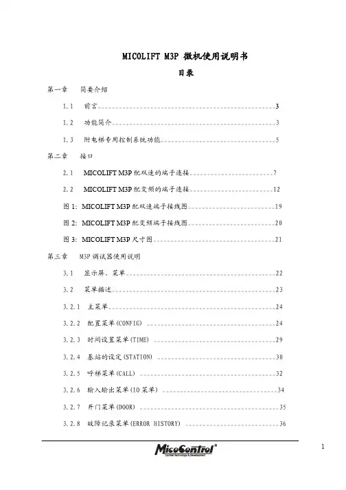
MICOLIFT M3P 微机使用说明书目录第一章简要介绍1.1前言___________________________________________________31.2功能简介_______________________________________________31.3附电梯专用控制系统功能_________________________________5第二章接口2.1MICOLIFT M3P配双速的端子连接________________________72.2MICOLIFT M3P配变频的端子连接________________________12图1:MICOLIFT M3P配双速端子接线图_________________________19图2:MICOLIFT M3P配变频端子接线图_________________________20图3:MICOLIFT M3P尺寸图___________________________________21第三章M3P调试器使用说明3.1显示屏、菜单___________________________________________223.2菜单描述_______________________________________________233.2.1 主菜单________________________________________________243.2.2 配置菜单(CONFIG) _____________________________________243.2.3 时间设置菜单(TIME) ___________________________________293.2.4 基站的设定(STATION) __________________________________303.2.5 呼梯菜单(CALL) _______________________________________323.2.6 输入输出菜单(IO菜单) _________________________________343.2.7 开门菜单(DOOR) ________________________________________353.2.8 故障记录菜单(ERROR HISTORY) ___________________________3613.2.9 密码菜单(PASSWORD) ____________________________________363.2.10脉冲监控菜单(PULSE MONITOR) ___________________________373.2.11输入选择菜单(INPUT SELECT)___________________________393.2.12时间菜单(TIME2)______________________________________403.3 自动测量井道数据方法_____________________________________403.4 电梯平层精度的调节_______________________________________413.5 减速距离的确定___________________________________________42第四章 故障描述_________________________________________________43 2第一章 简要介绍1.1 前言MICOLIFT M3P 全电脑控制微机自推出以来,以其无可比拟的可靠性、友好的人机界面,低廉的价格,迅速赢得了广大用户的信赖,成为电梯生产、改造及技术更新的首选产品,为当今电梯技术发展的主流方向。

CONTROL HEADREF.NO.PART NO.DESCRIPTIONREF.NO.PART NO.DESCRIPTIONBAR COPY IF NECESSARYLOW BAND RADIO ASSEMBLY 284180175A01Spring (3.05 MM OD), pivot 290310904A02Screw (3.5 x 6-PH-M)300480149A01Washer, captivitate 313280074A02Gasket, cable plug341484391F01Insulator Mica, transistor 350484180C01Washer, shoulder (nylon)360310905A01Screw, (9.0 x 6-FIL-M), transistor 371483572K01Insulator Mica, transistor39HLN4033BCover, bottom inner w/gasket(includes 1580004A01, cover, and 3280129F01, gasket400310906A19Screw (3.5 x 13-FH-M), inner cover 414280013A01Clip, coax (dress)440180701T74Conn. and Feed Through Caps 470780079A01Bracket, IC board support 492910271A15Pin, terminal512880141H03Plug, male (2.54 CTRS) (25 post)542880096A01Plug, male (3.96 CTRS)(4 post)553280080A01Gasket, antenna connector560280006A01Nut, spanner, antenna connector 570400114522Washer, lock, antenna connector 581480077A01Insulator, P.A. compartment 590780078A01Bracket, thermal device 602980014A01Clip, coax (terminal)631480179A01Insulator, mica10980028A01Socket, transistor2HLN4034C Bottom Cover, assembly40310906A05Screw (3.5 x 6-FH-M) bottom cover latch50180252J01Top Cover, assembly 64680026A01Stud Latch, top cover 87580178A01Pad, compression 90180252J01Housing, frame 104780027A01Pushbutton, latch 134180029A01Spring, latch140780016A02Bracket, lock slide 150780015A02Support, lock slide 164180022A01Spring, lock170310936B15Screw (3.5 x 13-FM-TH) holds lock slide 185584101B01Lock203280081A01Gasket, lock support 214380150A01Sleeve, cover release 235580002A01Handle240780113B01Spring, torsion 264780021A01Pin, pivotREF.NO.PART NO.DESCRIPTIONREF.NO.PART NO.DESCRIPTIONBAR COPY IF NECESSARYHIGH BAND RADIO ASSEMBLY 370310905A01Screw (3.0 x 6-FIL-M)392980014A01Clip, coax (terminal)40HLN4033BCover, bottom inner w/gasket (includes 1580004A01, cover and 3280129F01, gasket)410310906A19Screw (3.5 x 13-FH-M)434280013A01Clip, coax 442680211A01Shield, PA 455584300B04Handle, nylon460180701T74Conn. and Feed Through Caps 490780079A01Bracket, IC board support 512910271A15Pin, terminal520980028A01Socket, transistor 542880141H03Plug, male (25 post)572880096A01Plug, male (4 post)581580008A01Housing610280045A01Nut, retainer M5x1620200007003Nut, 8-32 x 5⁄16x 1⁄8hex643280080A01Gasket, antenna connector 650280006A01Nut, spanner 660400114522Washer, lock 671480077A01Insulator, PA680780078A01Bracket thermistar mounting12684716D01Heatsink3HLN4034C Bottom Cover, assembly 50310906A05Screw (3.5 x 6-FH-M)60180252J01Top Cover, assembly 74680026A01Stud, latch97580178A01Pad, compression 114780027A01Push Button 144180029A01Spring, latch150780016A02Bracket, lock slide 160780015A02Support, lock slide 174180022A01Spring, lock180310936B15Screw (3.5 x 13-FH-TH)195584101B01Lock213280081A01Gasket, lock support 224380150A01Sleeve, cover release 245580002A01Handle250780113B01Spring, torsion 274780021A01Pin, pivot294180175A01Spring (3.05 MM OD)300310904A02Screw (3.5 x 6-PH-M)310480149A01Washer, captive 323280074A02Gasket, cable plug 351484391F01Insulator, mica360484180C01Washer, shoulder nylonREF.NO.PART NO.DESCRIPTIONREF.NO.PART NO.DESCRIPTIONUHF ASSEMBLY410310906A19Screw (3.5 x 13-FH-M)434280013A01Clip, coax442680211A01Shield, PA455584300B04Handle, nylon460180701T74Conn. and Feed Through Caps490780079A01Bracket, IC512910271A15Pin, terminal520980028A01Socket, transistor542880141H03Plug, male (2.54 CTRS) (25 post)572880096A01Plug, male (3.96 CTRS) (4 post)604680009A01Stud, coil M6x1614680010A01Stud, coil M8x1.25620380012A03Screw, set M6x1630380256A01Screw, set M8x1.75640280045A03Nut, retainer M6x1.0650280045A02Nut, retainer M8x1.25670200007003Nut, 8.32 x 5⁄16x 1⁄8hex680480083A01Washer, stud device703280080A01Gasket, antenna connector710280006A01Nut, spanner720400114522Washer, lock7314-80077A01Insulator, PA740780078A01Bracket, thermal mount752980014A01Clip, coax (terminal)760780157A01Support, transistor PA771580003A01Housing, filter (harmonic)12684716D01Heatsink3HLN4034C Bottom Cover, assembly 50310906A05Screw (3.5 x 6-FH-M) 60180252J01Top Cover, assembly 70780015A02Stud, latch97580178A01Pad, compression114780027A01Push Button144180029A01Spring, latch150780016A02Bracket, lock slide160780015A01Support, lock slide174180022A01Spring, lock180310936B15Screw (3.5 x 13-FH-TH) 195584101B01Lock213280081A01Gasket, lock support 224380150A01Sleeve, cover release 245580002A01Handle250780113B01Spring, torsion274780021A01Pin, pivot294180175A01Spring (3.05 MM OD) 300310904A02Screw (3.5 x 6-PH-M) 310480149A01Washer, captive323280074A02Gasket, cable plug351484391F01Insulator, mica360484180C01Washer, shoulder370310905A01Screw (3.05 x 6-FIL-M) 390310936B06Screw (3.5 x 8-FILM-TF)40HLN4033B Cover, bottom inner w/gasket(includes 15-80004A01, cover)MOBILE MICROPHONESHMN1015AHLN4024Bmode while still on-hook arealso available.HLN4024BHang-up BoxHLN4025ATLN4698BCradle, Private-LineTLN4507ACradle with Slide SwitchTLN4505BCradle, Carrier SquelchHSN4009ACONTROL HEADSHLN4022EHLN4012ANOISE REDUCTION KITSSingle HousingConsists of a single housing with standard trunnion which can accommodate one, one board option and one alterna-tive control module.THN6125A HLN1002ATLN1391ATHN6125AMITREK SYSTEMS•90 ACCESSORIESHSN4010A Microphone Hang-upHLN4188AMOBILE ANTENNASRAB4012ARA RAB4013ARA&RAB4014ARA 6680385A04RSX4028AService Aids, Manuals SERVICE AIDSTEKA48。

MI理念手册A、品牌篇B、理念篇C、文化篇D、哲理篇E、训誓篇A、品牌篇品牌诠解:“品牌”是企业的核心价值所在,品牌的成功就是企业的成功,品牌的衰落就是企业的末日,品牌的知名度、信誉度、忠诚度就是企业的核心竞争力!一、品牌释义:“WINHERE”是“闻汇”的英文音译,含义为“赢在这里”,“此处助您成功”,阐述出公司与厂商、与客户双赢的经营理念。
二、名称释义:“文化·办公”既反映出文化与办公的复合商品结构、又展示出超市文化性的经营空间与经营理念。
“专业超市”则表达出超市专业性经营属性与主题式创新模式。
三、标识形象:标识以英文“WIN HERE”为主体加以局部形象变化,是国际主流的设计方式,简洁大气,识别性强。
首字母变形有五重含义。
一是仓房变型,表明仓储式、一站式大卖场的经营属性;二是笔尖变型,表明文化、办公用品的行业属性;三是动线指向标变型,以特有的超市符号表明业态属性;四是向上的箭头造型,象征企业不断上升的经营业绩与拼搏向上的企业文化;五是整体构成一列抽象的火车造型,象征企业的大规模、大物流、连锁化的经营前景。
标识主色:红色代表热情(服务业属性)、向上(企业精神)、胜利(企业愿景)。
蓝色代表广阔(事业前景)、深邃(企业理念)、规范(企业管理)、现代(业态特征)。
红蓝两色一动一静,一暖一冷,对比变化,形成丰满的企业图腾。
B、理念篇理念诠解:“理念”就是愿景与价值观,是对未来的理想与信念,是对事物的理解与观念。
企业必须具备集体高度认同的统一理念,全体员工心存共同愿景,奉行一致观念,才能发挥出团队的威力,形成加强的回路,提升扩张的速度。
一、事业理想:全面提升山西办公文化品味!由于我们的存在,为山西引进国内外先进的、前沿的、丰富的文化、办公商品,使山西消费者开阔视野、改善条件,提升办公文化水平;由于我们的努力,为山西传播国内外现代的、高效的办公文化理念,全面提升山西办公文化品味。
二、经营目标:1、建成并扩张国内首家复合型、体验式文化·办公主题连锁超市2、聚集资源,形成大物流;进行品牌资本运营和资源整合利用,建成量贩物流(批量物流)、OEM开发(自有产品)、品牌输出(加盟连锁)三条起飞跑道。


CORD118说明书features1.1990-1-1 to 2089-12-312.daily alarm with snooze function3.temperature measurement between –20c to +50c temperature measurement accuracy: max. +/- 1c temperature measurement resolution: 0.1c4.key tone5.3v operate6.production test7.book light function8.fm radio functionkey define1.mode key change mode / store setting2.set key set / change setting field3.up key increase setting with auto advance4.down key decrease setting with auto advance5.snooze key toggle between snooze funtion on/off6.c/f key toggle between c/f display fuctional descriptionstwo modes (date & time,alarm) *press <mode>key to change mode in the following sequence date & time mode *real time clock (hh:mm) with 12/24 hours display system. *day ofweek(sun,mon,tue,wed,thu,fri,sat) *temperature(c or f)*month and date (mm-dd)alarm mode*alarm time (hh:mm) with 12/24 hours display system *day of week (sun,mon,tue,wed,thu,fri,sat) *alarm text*month and date (mm-dd)*change back to date & time mode automatically after 8 seconds idle. time setting*press<set> key for 2 seconds at date & time mode *the order of setting is as follows: *press <up>or<down>key to change the flashing value an press<set>key to setup next item. *press <mode>key to save the setting, the day of week will setupautomatically.*change back to date & time mode automatically after 8 seconds idle. alarm time setting*press <set>key at alarm mode *the order of setting is as follows: *press <up> or <down>key to change the flashing value and press<set> key to setup next item. *press<mode>key to save the setting and return to alarm mode. *change backto date & time mode automatically after 8seconds idle. *press <up> key to toggle alarm on/off ,press<down>key to togglechime on/off.*there is 30 seconds buzzer sound when alarm time is reached, press any key tostop the buzzer sound.*if snooze is on , these are 2 reminiscent buzzer sounds for 30 seconds after5 minutes each. press any key to stop the buzzer sound. alarm trigger output*when there is 30 seconds buzzer sound, the iob3 is output high at the same time. *the iob3 output high in the daily alarm and the snooze alarm only. book lightoperation:*press the “light” button rig ht side of book light. *the book light on within 5 second. *can adjust the angle of the light attain best. *open the battery door change batteries. *use ag13 buttery.*don’t mix old new batteries. *don’t displace of batteries in fire. batteries many explode or leak. fm radio *turn on the volume button*make the antenna.*press <reset> then <scan> to auto – scan.篇二:vhh118b 电话交换机说明书篇三:说明书1.零件的分析1.1零件的作用题目给定的零件是变速箱体零件,是变速箱的基础零件,它把有关零件连接成一体,使这些零件保持正确的相对位置,彼此能协调地工作。
PagiñaSeguridad (65)Mandos (75)Instalación (76)Operación (80)Localización de fallas (83)Mantenimiento (85)Almacenamiento (89)Especificaciónes (90)Garantia (91)Toda información, ilustraciónes, y especificaciones en este manual sebasa en información lo último que disponible al tiempo de publicación. Sereserva el dercho de efectuar combios sin previo aviso.INSPECCIONES UNIDADAsegúrese que todas tapas, guardias, y escudos son ajustados y en posición.Encuentre todos controles operando y etiguetas de seguridad.Inspeccione cordón eléctrico para daño antes de usando. Hay un riesgo de electrocución de aplastante, cortando, o daño de calor.SERVICIO CON CIUDADO UNIDADApague la unidad, desconéctela de la red eléctrica, y permita que la unidad se enfrié antes de repararla.Preste servicio en un área limpie, seca y planca. Embraque el freno para evitar el movimiento de la unidad.A -- GeneradorB -- BombaC -- Cristal De la Vista Del AceiteD -- ManijaE -- Depósito De GasolinaF -- MotorG -- Guardia del cintúronH -- Válvula de descargardel tanque de aireI -- Indicador de presiónAFBGECIA -- GeneradorB -- BombaC -- Cristal De la Vista Del AceiteD -- ManijaE -- Depósito De GasolinaF -- MotorG -- Guardia del cintúron H -- Válvula de descargar del tanque de aire I -- Indicador de presiónAFBGECHIALTITUD ALTAEn altitud alta, la mezcla de aire/combustible del carburador estandard será demasiado rico. Función disminuirá y consumpción de combustible aumentará. Una mezcla muy rica también ensucia la bujía en los motores de gasolina y puede dificultar el arranque. Operación a una altitud que es diferente de altitud donde el motor fue certificado, para una extensión de mucho tiempo, puede aumentar emissiones. Función de altitud alta puede mejorar de modificaciones especificos al carburador. Si siempre operar su unidad a altitudes más de 5,000 pies (1500 metros), su concesionario haga esta función de modificación a carburador. Este motor, cuando operando a altitud alta con modificaciones a carburador para uso en altitud alta, encontrará cada estandard de emissión en toda vida de uso.Con modificación de carburador, caballo de fuerza de motor disminuirá sobre 3.5% para cada 1,000 pies (300-metros) aumento en altitud. Este efecto de altitud en caballo de fuerza será más grande de este si no haga modificación de carburador.NOTA: Cuando el carburador modificó para operación altitud alta, la mezcla de aire/combustible será demasiadodelgado para uso en altitud abajo. Operación aaltitudes abajo de 5,000 pies (1500 metros) concarburador modificado causaría recalentado de motory resultaría en daño serio de motor.Para uso a altitudes abajos, vuelva carburador aconcesionario de servicio a especificados orginalesde fábrica.OPERACIÓNOperación:1. Leer atentamente las advertencias de seguridad antes de efectuaresta operación.NOTA: Desenchufe todo el equipo de los receptáculos de energía antes de comenzar la unidad.2. Colocar muletilla que estar en la arriba de válvula pilota a posición vertical. Este dar una empezada sin descargar. Este compresor de aire puede descargar y tener una empezada de motor más facil.3. Encender el motor. (Referir a manual de este unito de motor.)4. Despues de 1-2 minutos de funcionando, poner muletilla en posición orginal.5. Ajustar la presión moviendo el regulador de presión en el sentido contrario a las manecillas del reloj para reducir la presión y en el sentido de las manecillas del reloj para aumentaria. (La presión real de entrega pueden variar de un nivel de presión máxima de la bomba).6. Asegúrese que unidad toma a tierra. Vea Instrucciones de Conexión a Tierra.7. Cargas pueden aplicar a unidad ahora.NOTA: Este motor está protegido con un sistema que para el motor cuando el aceite alcanza un nivel muy bajo. Elmotor no volverá a arrancar si no se agrega aceite.En caso de ruidos o vibraciones anómalos, detenerel compresor de aire y consultar la sección "Localizaciónde Averías".Apagamiento:1. Quite todas cargas como desconecten cordones électricos y apagadando aparatos électricos.2. Para parar el compresor de aire mover el boton de motora posición de "OFF". (Referir a manual de motor de este unito.)3. Descargar el aire de los depósitos de aire, por medio de una herramienta conectada o tirando los anillos de la válvula de seguridad.4. Una vez que le presión en el interior de los depósitos de aire es inferior a 10 libras, abrir la válvula de descarga debajo de cada depósito de aire para eliminar la humedad.5. Dejar enfriar el compresor de aire.6. Limpiar el compresor de aire con un paño y colocarlo en un lugar seguro, donde no exista el riesgo de congelación.82 Manual del OperadorManual del Operador83Síntoma Problema Soluciones El motor no encender. Varias problemos de motor. Referir a manual de motor de sucompresor de aire.Funcionamiento ruidoso. Polea de motor o bomba de rueda Apretar polea y/o rueda volado. voldao es suelto.Falta aceite en la bomba. Reponer la cantidad de aceitenecesaria. Controlar que los cojinetesno se hayan dañado.Residuos de carbono en los pistones o Desmontar e inspeccionar la culataen las válvulas. del cilindro. Limpiar y sustituir.Avería del cojinete, pistón o biela. PARAR EL COMPRESOR! Póngaseen contacto con la Asistencia Clientes.Abajo de presión en tanque de Los accesorios no han sido apretados Aretar los accesorios donde se oye aire o abajo de presión bien. que el aire dale. Controlar losrapidamente cuando el compresor accesorios con una solución de agua y de aire está apagado. jabón. No apretar demasiado. La válvula de retención y la válvula Desmontar, limpiar o sustituir. piloto es defectuose. Fugas de aire del depósito de aire. Sustituir el depósito de aire. No intentar reparar el depósito.Presión insuficiente en la Fugas de aire. Localizar las fugas y reparar. herramienta o en los accesorios. Filtro aspiración aire obstruido. Limpiar o sustituir.Los tubos o los empalmes de los Sustituir con tubos o empalmes más tubos son demasiado pequeños grandes.o largos.El compresor de aire no produce la Controlar el requisito de aire delcapacidad de aire requerida. accesorio. Si es superior al CMF o a la presión suministrada or el compresor de aire, es necesario usar uncompresor más grande.El regulador de presión no ha sido Ajustar el regulador de presión al ajustado a una presión suficientemente valor adecuado o sustituir. alta o avería del regulador de presión.Las resbalaban de correa. Haga mas apretado o reemplace. Válvula pilota restrica. Limpie o reemplace.El aire sale de la válvula de La válvula de seguridadActivar la válvula de seguridad seguridad. probablemente es defectuosa. manualmente tirando del anillo. La presión de aire en el depósito Si el aire sigue saliendo, debe ser es excesiva. sustituida. Interruptor motor/presióndefectuoso. Sustituir.84Manual del OperadorSíntoma Problema Soluciones No hay salida de voltaje del Arranque de control de marcha en Coloque control de marcha en vacío. unidad.vacío.Serie de cordon o extensiones Revise capabilidades de series de inadecuados. cordon o extensiones.Fugas de aire en la bomba. Juntas defectuosas. Apriete los pernos en el compresor usando la fuerza de torsión correcta oreemplace las empaquetaduras.Soufflement d'air provenant Soupape (reed) d'admission Sustituir.du filtre d'admission d'air. défectuuese.Condensación en el aire de Condensación en el depósito de aire Opera el compresor de aire por una descarga. debido a una elevada humedad hora para impedir demasiadoatmosférica o el compresor de aire condensión. Vaciar el depósito de aire no ha funcionado por un tiempo después de cada empleo. Vaciar el suficiente. depósito de aire más frecuentemente en climas húmedos y usar un filtro enla línea de aire.Excesivo consumo de aceite en Filtro aspiración aire obstrucido. Limpiar o sustituir.la bomba. Compresor de aire sobre superficie No inclinar el compresor de aire no nivelada. a un ángulo superior a 10° en ninguna dirección mientras estéen marcha.Cárter demasiado lleno de aceite. Vaciar el aceite. Reponer con aceitehasta el nivel apropiado.Viscocidad incorrecto. Elimina el aceite. Llene al nivelcorrecto con SAE-30W aceite sin detergente.Pérdidas de aceite. Apriete los pernos en el cabeza del compresor usando la fuerza de torsióncorrecta o reemplace las empaquetaduras.Anillos del pistón desgastados o Ponerse en contacto con la Asistencia cilindro rayado. Clientes.Respirado de cárter es taparo. Limpiar o sustituir.Condensación en el aire de Condensación en el depósito de aire Opera el compresor de aire por una descarga. debido a una elevada humedad hora para impedir demasiadoatmosférica. condensión. Vaciar el depósito de aire después de cada empleo. Vaciar el depósito de aire más frcuentemente en climas húmedos y usar un filtro en la línea de aire.No hay salida de voltaje del Serie de cordon o extensiones Revise capabilidades de series de unidad. inadecuados. cordon o extensiones en sección de Controles; Tamaño de Cable en este manual. Consultar con unconcesionario de distribuidor.Manual del Operador 8586 Manual del OperadorManual del Operador 87(Fig. 3)88 Manual del OperadorManual del Operador 8990 Manual del OperadorANOTE NÚMERO SERIEEscriba número de modelo, numero serie de máquina (vea etiqueta de número serie (A) en ilustración y fecha de compra en espacios abajo. Su concesario necesita esta información cuando ordenando partes.Num. de modelo _________________________________________Num. serie de máquina ___________________________________ Fecha de compra ________________________________________ (llene de comprador)ARTÍCULOESPECIFICACIÓNESUnit *AG2-PH13-08M1 *AG2-SH13-08M1 **AG2-SH13-30M ***AG2-SH13-B *AG2-PS14-08M1 *AG2-SS14-08M1 **AG2-SR14-30M ***AG2-SS14-B*AG2-PK14-08M1*AG2-SK14-08M1 **AG2-SK14-30M ***AG2-SK14-B*AG2-PM14-08M1 *AG2-SM14-08M1 **AG2-SM14-30M ***AG2-SM14-BMotor Honda Subaru Kohler Mi-T -M Motor HP 13141414Aceite (L)1.09 L1.19 L1.30 L0.94 LVatios con el compresor 3500Vatios sin el compresor 3000Tension nominale (V)120V Frecuencia (Hz)60 Hz Bomba Compresor Bifásico Aceite (L)0.73 LDepósito Aire (L)*30.3 L **113.5 L ***N/APresión máximo (psi)175 PSIARTÍCULO ESPECIFICACIÓNESUnit AG1-PH65-08M1AG1-PR07-08M1AG2-SKD-30MMotor Honda Subaru Kohler Motor HP 6.579.1Aceite (L)0.59 L0.59 L1.41Vatios con el compresor 16002750Vatios sin el compresor 6001800Tension nominale (V)120V Frecuencia (Hz)60 HzBomba Compresor Monofásico Bifásico Aceite (L)0.74 L 0.73 L Depósito Aire (L)30.3 L 113.5 L Presión máximo (psi)125 psi175 psiDECLARACIÓN DE GARANTÍAMi-T-M garantiza que todas las piezas (excepto aquellas a las que se hace referencia abajo), de su nueva generador libres de defectos en materiales y mano de obra durante los periodos siguientes:Por dos (2) años a partir de la fecha original de compra:Bomba de Compresor CañeriasTanqueGeneradordeAsambleaPor seis (6) mes a partir de la fecha original de compra:Interruptor de Presión ReguladoresVàlvula de revisar Válvula de pilotoLinea de cobre/acero inoxidablePor noventa (90) días a partir de la fecha original de compra:Indicadores de presión Válvula de alivio de seguridadVálvulas de desagüeLas piezas defectuosas que no están sujetas a deterioro causado por el uso seránreparadas o reemplazadas a nuestra opción durante el periodo de garantía. En todo caso, el reembolso está limitado al precio de compra pagado.EXCLUSIONES1. El motor está cubierto bajo una garantía separada proporcionada por el fabricante respectivo y estásujeta a los términos en ella establecidos.2. Partes de desgaste normal:Aisladores Filtro de aire3. Esta garantía no cubre las piezas dañadas debido al deterioro normal causado por el uso, mala aplicación,mal uso, operación a velocidades, presiones o temperaturas diferentes a las recomendadas. Las piezasdañadas o gastadas a causa del uso de líquidos cáusticos o por la operación en medios ambientesabrasivos o corrosivos o bajo condiciones que causan cavitación de la bomba no están garantizadas.La falla en seguir los procedimientos recomendados de operación y mantenimiento también cancela lagarantía.4. Cobras de trabajar, peridio o daño resultando de operación mala, mantenimiento (otro de descarga detanque de aire rutina y cambios de aceite si aplica) o reparaciones hace por personas otro de Mi-T-MCentro de servicio autorizado.5. El uso de piezas de repuesto diferentes a las genuinas Mi-T-M cancelará lagarantía. Las piezas devueltas, con franqueo pagado a un Centro de Servicio AutorizadoMi-T-M serán inspeccionadas y reemplazadas, libre de cargos, si se determina que están defectuosas ysujetas a la garantía. No existen garantías que se extiendan más allá de la descripción contenida aquí.Bajo ninguna circunstancia Mi-T-M será responsable por la pérdida de uso de la unidad, pérdida detiempo, inconvenientes, pérdida comercial o daños consecuentes.PARA SERVICIO O CONSIDERACION DE LA GARANTIA CONSULTE CON:Mi-T-M® Corporation/50 Mi-T-M Drive, Box 50/Peosta, IA 52068-0050Telefono: 563-556-7484 / 800-553-9053 / Fax 563-556-1235Lunes - Viernes 8:00 a.m. - 5:00 p.m. CSTManual del Operador 9192Manual del Operador Manufactured by Mi-T -M 50 Mi-T -M Drive, Peosta IA 52068563-556-7484/ Fax 563-556-1235。
ICOM 2720中文参考说明书✧内容目录前言i重要i注意事项ii包含配件iii内容目录iii快速指导I-XII◆安装I◆首次通连VIII◆中继台操作X◆频道储存XI1 描述◆前面版-控制面版 1◆功能显示 3◆主机 5◆HM-133手眯7◆手眯键盘8◆可选手眯102 设臵频率11-15◆准备11◆使用DIAL旋钮13◆使用上下键13◆使用键盘13◆步进选择14◆锁定功能153 基本功能操作16-12◆接收16◆监听功能16◆SQL 压制衰减17◆V/V U/U同时接收18◆次要段静音、提示19◆发射20P. iv◆选择发射功率20◆单触PTT功能21◆静音功能214 中继台操作22-28◆概要22◆使用中继台23◆亚音25◆差频27◆自动差频285 存储操作29-37◆概要29◆存储频道选择29◆编辑存储频道30◆传送频道内容32◆消除存储34◆存储段选择35◆存储段设臵36◆传送段内容376 CALL频道操作38-39◆CALL频道选择38◆CALL频道传送38◆编辑CALL频道397 扫描操作40-45◆扫描类型40◆扫描开始/停止41◆扫描边界定义42◆屏蔽频道设臵44◆扫描恢复条件458 优先监视46-47◆优先监视类型46◆优先监视操作479 DTMF存储编码48-51◆定义DTMF码48◆发射DTMF码50◆DTMF速度5110 ‚POCKET BEEP‛与亚音抑制静噪◆‚POCKET BEEP‛操作52◆TONE/DTCS 抑制操作54◆TONE扫描5511 其他功能56-72◆设臵模式56◆初始化模式60◆AM/FM窄调制模式64◆天气台操作(美版机)65◆手眯键盘66◆部分重臵67◆全重臵67◆数据克隆68◆信息包操作6912 维护73-74◆故障排除73◆保险管更换7413 规格及可选择配件75-76◆规格75◆可选配件7614 模式管理77-78P. I✧快速参考安装一体安装需要使用MB-85组合架将控制板与主机固定在一起(20CM连接线与MB85一同供应)。