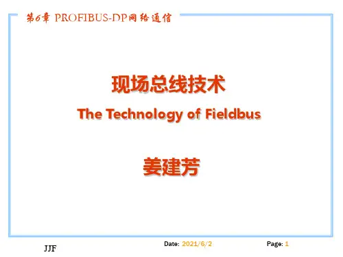
最完美的PROFIBUS通讯教材
- 格式:ppt
- 大小:4.73 MB
- 文档页数:212
驱动_PROFIBUS通讯方式设置说明一、问题描述本说明介绍了西门子S7系列PLC在MCGS中使用PROFIBUS通讯方式较常遇到的问题,并提供了详细的问题处理方案。
二、适应对象1、硬件条件PROFIBUS-DP主站可以是带有集成DP口的CPU(例如S7-300 315-2DP),或者用CP342-5扩展的S7-300站、IM467、CP443-5Extend扩展的S7-400站。
上位机中插有通信卡CP5411、CP5511、CP5611、CP5611-A2、CP5412、CP5613,也作为PROFIBUS-DP主站。
PROFIBUS-DP从站有ET200系列、调速装置、S7-200/300/400站及第三方设备等(例如S7200 PLC扩展EM277通信模块)。
通讯电缆一条,也可以自己制作。
若有多个PLC,则可以把所有的3对3,4对4,5对5,8对8接线。
2、软件条件(1)操作系统要求是Windows2000 Professional SP4版本或Windows98 SE操作系统推荐使用Windows2000 Professional SP4操作系统。
(2)支持软件必须安装西门子SoftNet软件,SoftNet版本为V5.3 Build 1381。
西门子安装光盘为:SIMATIC NET CD: 05/2000。
要安装的内容:光盘目录下:\sw \sn_pb_s7\ disk1\ Setup.exe光盘目录下:\sw \VBasic\ S7\disk1\ Setup.exe。
(3)PLC编程软件若PROFIBUS-DP主站使用的是S7-300 PLC或S7-400 PLC,必须装有Step7 5.0以上的编程软件,推荐使用Step7 V5.2。
注:MCGS ProfibusDP驱动是调用SoftNet来实现通讯的,所使用SoftNet(V5.3 Build 1381)版本对操作系统有要求,只能在Window 2000 Pro或Windows98 SE系统上使用,而无法用于Windows2000 Server、WindowsXP或更新的操作系统上。


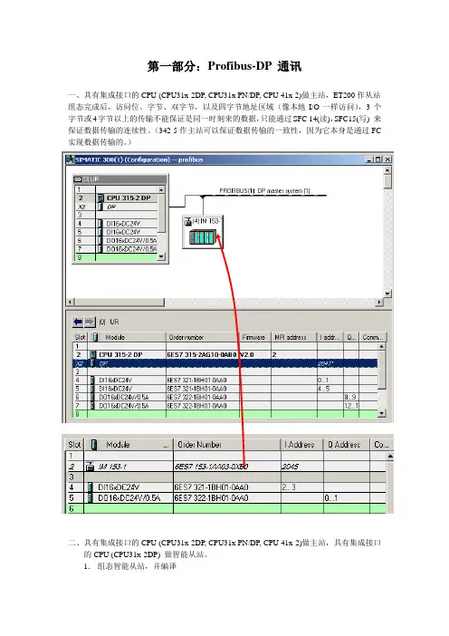
第一部分:Profibus-DP 通讯一、具有集成接口的CPU (CPU31x-2DP, CPU31x PN/DP, CPU 41x-2)做主站,ET200作从站组态完成后,访问位、字节、双字节,以及四字节地址区域(像本地I/O一样访问),3个字节或4字节以上的传输不能保证是同一时刻来的数据,只能通过SFC 14(读),SFC15(写) 来保证数据传输的连续性。
(342-5作主站可以保证数据传输的一致性,因为它本身是通过FC 实现数据传输的。
)二、具有集成接口的CPU (CPU31x-2DP, CPU31x PN/DP, CPU 41x-2)做主站,具有集成接口的CPU (CPU31x-2DP) 做智能从站。
1.组态智能从站,并编译2. 组态主站在主站的HW Config 中组态DP 口,并将其Operation Mode 设置成Dp master, 将目录中“profibus DP ”—“Configured Stations ” —“CUP 31x2DP ”拖拽到DP 网络上,配置“connect ”和“configuration ”属性,完成configuration 配置如上图所示。
(配置中的I/O 模块是虚拟的,用来实现数据交换,不能和自身I/O 模块的地址冲突 Unit :一个word ,一个word 的发;All :一起发MS 模式为主从模式,DX 模式为直接数据交换模式)通过PG 监控通讯3. 下装,监视通过MPI 将程序下装,由于找不到 虚拟IO 会使系统停机,将OB82,OB85下装,各自建立变量表,观察收发情况(可以切换到Profibus 网络,在通过profibus 进行同时监控,有可能发生不能同时监控的情况,在不能监控的模块里可以写一段move 指令。
)例如:三、CP342-5做主站,ET200做从站1. 将CP342-5组态为主站模块OB1: L IB 0 T QB 0 NOP 0 (IB0为实际模块)2. 组态ET2003. 编写程序(1) 将IW12发送到ET200的DO 模块。
点对点广播和局部广播通信可以提供大量的产品如
变量参数程序均设计为对象
如变量数组记录如程序
访问此对象的号
此对象的数据类型
如
对象全名
对象的实六位地址如
用户定义
如布尔整数
如停机时间
这些部分是可选的
仅对某些设备存在
名字长度访问保护
OD 的第一个指针和长度
简单变量变量类型如整数
数组同类型的简单变量的数组记录
区域
事件
程序调用
变量表简单变量
设备都支持只有下划线的服务对其他服务的选择在行规中规定
开始停止继续复位删除开始停止
继续复位删除
站之间的数据传输通过通信关系来执行
主从从主主主
读请求指针
)文件包括所有相关设备的通信能力
在组态期间FMS 文件并将所有信息放入账号
中描述了文件的格式。
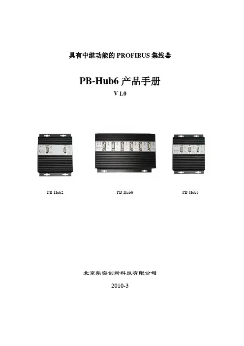
具有中继功能的PROFIBUS 集线器PB-Hub6产品手册V 1.0PB-Hub2PB-Hub6PB-Hub3北京鼎实创新科技有限公司2010-3目录第一章产品概述 (2)1. 产品系列 (2)2. PROFIBUS集线器技术概念 (2)2. PROFIBUS集线器PB-Hub6主要用途 (3)3. 产品特点 (4)4.技术指标 (5)第二章产品结构、安装、指示灯 (6)1.产品外形 (6)2. 外形尺寸 (6)3. 安装 (6)4.电源 (7)5.指示灯 (7)6.上电步骤及故障排除 (8)第一章 产品概述具有中继功能的PROFIBUS 集线器PB-Hub6(以下简称PROFIBUS 集线器或集线器),应用于PROFIBUS 现场总线网络中,可将网络的总线型拓扑结构改变为树型结构或混合型结构,同时保留了中继器的技术功能。
本装置以方便工程现场的安装布线、增加网络的传输距离和站点个数为目的, 同时还具有网络隔离和通信诊断功能。
1. 产品系列PROFIBUS 集线器PB-Hub6是北京鼎实创新科技公司网络部件系列中的产品。
网络部件系列产品型谱见下表1-1所示:表1-1 网络部件系列产品列表:型号品名网络协议技术指标其他网络协议¾ 6 PROFIBUS DP 接口¾波特率自适应0~12M PROFIBUS 集线器 其他标准 PB-Hub6PROFIBUS¾无主/从端口之分别RS485网络¾物理层转换,与上层协议无关PB-Hub3同上 PROFIBUS其他标准 ¾3 PROFIBUS DP 接口RS-485网络 ¾其余同上PB-Hub2 PROFIBUS 中继器 PROFIBUS其他标准¾2 PROFIBUS DP 接口 RS-485网络¾其余同上¾波特率:9.6K~12M ,拨码开关设置¾光纤类型:多模玻璃光纤,波长850nm 其他标准 PB-OLM02 PROFIBUS 光纤模块 PROFIBUS¾光纤通讯距离:2Km RS485网络¾光纤接口类型:4×ST 口 ¾光纤链路模式:总线型,星型¾2×9孔D 型 PB-DS50BPROFIBUS 插头 PROFIBUS其他标准¾终端电阻开关 RS485网络 ¾诊断指示灯 ¾2×9孔D 型 CO-CNCT-2CANopen 插头 CANopen其他标准¾终端电阻开关 CAN 网络¾诊断指示灯2. PROFIBUS 集线器技术概念PROFIBUS-DP 采用基于RS485技术的物理层,是目前应用最普遍的一种形式。

profibus dp通讯使用说明Profibus DP通讯使用说明简介Profibus DP是一种用于工业自动化领域的通信协议,具有高速、可靠、实时性好等特点。
本文将对Profibus DP通讯进行详细说明。
Profibus DP的特点•高速性: Profibus DP支持高达12 Mbit/s的通信速率,能够满足大多数工业自动化应用的通信需求。
•可靠性: Profibus DP采用了差分信号传输和冗余通信机制,使得通信稳定可靠,抗干扰能力强。
•实时性: Profibus DP能够在实时的控制系统中使用,确保传输数据的及时性和准确性。
•灵活性: Profibus DP支持多种拓扑结构,如总线型、星型、环型等,可根据实际应用需求进行灵活配置。
Profibus DP的硬件连接使用Profibus DP进行通讯时,需要注意以下硬件连接的要点:1. 使用正确的通讯电缆进行连接,确保电缆符合Profibus DP的标准,包括电缆类型、屏蔽要求等。
2. 通过正确的连接器将各个设备连接到Profibus DP总线上,确保连接器的质量和稳定性。
3. 确保每个设备的地址设置正确,避免地址冲突导致通讯故障。
4. 对于较长的总线长度,需要使用合适的终端电阻进行衰减和防止信号反射。
Profibus DP的通讯配置在使用Profibus DP进行通讯前,需要进行相关的通讯配置,具体步骤如下: 1. 对于每个设备,需要在控制系统中进行设备参数的配置,包括设备地址、通信速率等。
2. 确定需要进行通讯的数据类型和数据量,并进行相关的参数设置。
3. 配置控制系统的通讯模块,确保其支持Profibus DP通讯,并进行相应的配置和参数设置。
Profibus DP的应用领域Profibus DP在工业自动化领域具有广泛的应用,包括但不限于以下几个方面: - 工业控制系统中的数据采集与传输 - 设备之间的联网和通讯 - 远程监控和控制 - 传感器与执行器的连接与控制总结Profibus DP通讯是一种高速、可靠的通信协议,适用于工业自动化领域的各种应用。
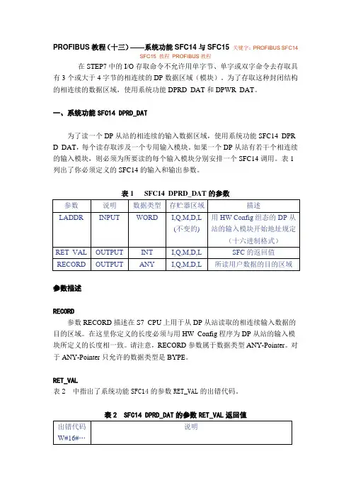
PROFIBUS教程(十三)——系统功能SFC14与SFC15关键字:PROFIBUS SFC14SFC15 教程PROFIBUS教程在STEP7中的I/O存取命令不允许用单字节、单字或双字命令去存取具有3个或大于4字节的相连续的DP数据区域(模块)。
为了存取这种封闭结构的相连续的数据区域,使用系统功能DPRD_DAT和DPWR_DAT。
一、系统功能SFC14 DPRD_DAT为了读一个DP从站的相连续的输入数据区域,使用系统功能SFC14 DPR D_DAT,每个读存取涉及一个专用输入模块。
如果一个DP从站有若干个相连续的输入模块,则必须为所要读的每个输入模块分别安排一个SFC14调用。
表1列出了你必须定义的SFC14的输入和输出参数。
表1 SFC14 DPRD_DAT的参数参数描述RECORD参数RECORD描述在S7 CPU上用于从DP从站读取的相连续输入数据的目的区域。
在这里你定义的长度必须与用HW Config程序为DP从站的输入模块所定义的长度相一致。
请注意,RECORD参数属于数据类型ANY-Pointer。
对于ANY-Pointer只允许的数据类型是BYPE。
RET_VAL表2 中指出了系统功能SFC14的参数RET_VAL的出错代码。
表2 SFC14 DPRD_DAT的参数RET_VAL返回值二、系统功能SFC15 DPWR_DAT从S7 CPU传送一个连续的输出数据到DP从站,使用系统功能SFC15 DP WR_DAT。
每个写存取涉及一个专用的输出模块。
如果DP从站有若干个连续的数据输出模块,则对每个要写入的输出模块必须分别安排一个SFC15调用。
表3指出了必须定义的SFC15的输入和输出参数。
表3 SFC15 DPWR_DAT的参数参数描述RECORD参数RECORD描述要从S7 CPU写入DP从站的连续的输出数据的源区域。
在这里指定的长度必须与用HW Confi组态的DP从站的输出模块的长度相一致。
目次1前言 (2)2RS-485简介 (2)2.1RS-485的规范 (2)2.2RS485应用中常见的问题 (3)2.2.1 最多可带收发器(即节点数)的数目 (3)2.2.2关于终端匹配 (4)2.2.3引出线(分支)的长度 (5)2.2.4关于偏置电阻 (5)3PROFIBUS-DP总线应用说明 (8)3.1标准最大配置 (8)3.2支持的传输速率 (8)3.3传输介质 (8)3.4传输线最大距离 (9)3.5长距离时节点数的计算 (9)3.5.1FM1模块的数据量 (9)3.5.2MACS系统数据交换周期的概念 (10)3.5.3数据交换周期的工程应用 (10)3.6重复器与终端匹配器的应用 (11)3.7通过重复器改变网络拓扑结构 (11)P rofibus-DP总线Profibus-DP 总线1前言目前用于过程控制的多种通讯协议中Profibus-DP、Arcnet、和CAN 的物理层均是RS-485规范。
本手册围绕RS-485的理论和应用要点,对Profibus-DP的物理层进行工程应用上的说明。
读者如果熟悉第2节内容,可以跳过不阅。
2RS-485简介2. 1 RS-485的规范RS-485标准采用平衡式发送,差分式接收的数据收发器来驱动总线,是EIA制定的一种支持多节点、远距离和接收高灵敏度的串口总线标准。
其具体规范如表1。
表1 RS-485电气规范2.2 RS485应用中常见的问题2.2.1 最多可带收发器(即节点数)的数目RS485允许连接的收发器数标准并没有规定,但规定了最大总线负载为32个单位负载(UL ),每单位负载的最大输入电流为1.0mA/-0.8mA ,相当于约12K 欧。
实际信号在电缆的传输过程中受传输衰减、信号反射、带载能力的影响。
因此直接所带的节点数目有限。
为了扩展节点数目,一般有两种做法,其一是采用重复器,通过重复器的信号整形、放大、转发,将节点数目扩大。
DVPPF02-SLPROFIBUS DP Slave Communication Module Operation ManualDVP-0155320-01Warning3 This operation manual provides introduction on the functions, specifications, installation, basic operation,settings and network protocol for DVPPF02-SL.3 This is an OPEN TYPE device and therefore should be installed in an enclosure free of airborne dust,humidity, electric shock and vibration. The enclosure should prevent non-maintenance staff fromoperating the device (e.g. key or specific tools are required to open the enclosure) in case danger and damage on the device may occur. DO NOT touch any terminal when the power is switched on.3 Please read this operation manual thoroughly and follow the instructions in case damages on the device or injuries on the operation staff occur.Table of Content1Introduction to DVPPF02-SL (2)1.1Features (2)2Product Profile and Outline (2)3Installation (4)3.1Dimensions (4)3.2Connecting DVPPF02-SL to PLC MPU (4)3.3Installing DVPPF02-SL and PLC MPU on DIN Rail (4)3.4PIN Definition for PROFIBUS DP Port (5)3.5Connecting to PROFIBUS DP Port (5)3.6Address Switch (5)4Establishing PROFIBUS DP Network by DVPPF02-SL (6)5Transmission Distance and Baudrate (6)6GSD File (7)7Mapping Areas and Status Registers (7)8Configuring DVPPF02-SL (8)8.1Configuring DVPPF02-SL (8)8.2I/O Configuration for DVPPF02-SL (8)9LED Indicators and Trouble-shooting (9)10Application Example (10)1 Introduction to DVPPF02-SL1. Thank you for choosing Delta DVPPF02-SL PROFIBUS DP slave communication module. To ensurecorrect installation and operation of the product, please read this operation manual carefully before using it.2. This operation manual only provides introductory information on DVPPF02-SL. For more detailedinformation on the PROFIBUS DP protocol, please refer to relevant references or literatures.3. DVPPF02-SL is a PROFIBUS DP slave communication module, used for connecting the DeltaDVP-SV and DVP-SX2 series PLC to the PROFIBUS DP network. DVPPF02-SL is a left-sideextension module, and no external power supply is required when using it. The power is supplied by the PLC MPU (main processing unit).1.1 Featuresz Supports the loop data transmission between the PROFIBUS DP master and many slaves.z Auto-detects baudrate; supports max. 12M bps.z Self-diagnosisz A PLC MPU is extendable to max. 8 modules on its left hand side.z Supports max. 100 words of I/O output and 100 words of I/O input.2 Product Profile and Outline2.1 Product Profiles1 Interface for left-side I/O module2 I/O module fastening clip3 I/O module positioning hole4 POWER indicator5 NET indicator6 PROFIBUS DP port7 DIN rail clip 8 Digital display 9 Address switch10 Positioning clip 11 Nameplate 12I/O module interface(35mm)railDIN13DVP-PLC Operation Manual 22.2 SpecificationsPROFIBUS DP PortInterface DB9connector Transmission method High-speed RS-485Transmission cable Shielded twisted pair cableElectrical isolation 500 VDCCommunicationData type Cyclic data exchangeModule name DVPPF02-SLGSD document DELA0AFE.GSDProduct ID 0AFESerial baudrate supported (auto-detection) 9.6k, 19.2k, 93.75k, 187.5k, 500k, 1.5M, 3M, 6M, 12M bps (bits/second)Electrical SpecificationPower supply voltage 24 VDCInsulation voltage 500 VDCPower consumption 2 WWeight 115g EnvironmentInterference immunity ESD (IEC 61800-5-1, IEC 6100-4-2)EFT (IEC 61800-5-1, IEC 6100-4-4)Surge Teat (IEC 61800-5-1, IEC 6100-4-5)Conducted Susceptibility Test (IEC 61800-5-1, IEC 6100-4-6)Storage/operation Operation: -10 to 50°C (temperature), 90% (humidity) Storage: -25 to 70°C (temperature), 95% (humidity)Shock/vibration immunity International standards: IEC 61800-5-1, IEC 60068-2-6/IEC 61800-5-1, IEC 60068-2-273 Installation3.1 DimensionsUnit: mm3.2 Connecting DVPPF02-SL to PLC MPUz Open the fastening ports for the I/O module on the left hand side of the PLC MPU and insert the DVPPF02-SL alongside the fastening clips, as c.z Press the clips to make sure the connection is tight, as d.3.3 Installing DVPPF02-SL and PLC MPU on DIN Railz Use 35mm DIN rail.z Open the DIN rail clips on DVPPF02-SL and the PLC MPU. Insert DVPPF02-SL and the PLC MPU onto the DIN rail.z Clip up the DIN rail clip on DVPPF02-SL and the PLC MPU to fix them on the DIN rail.DVP-PLC Operation Manual 43.4 PIN Definition for PROFIBUS DP PortPINNameDefinition1 -- N/C2 -- N/C3 RxD/TxD-P Sending/receiving data P (B)4 --N/C5 DGND Data reference potential (C)6 VP Power voltage - positive7 -- N/C8RxD/TxD-NSending/receiving data N (A) 9 --N/C3.5 Connecting to PROFIBUS DP PortInsert the PROFIBUS DP bus connector into the PROFIBUS DP port on DVPF02-SL. Screw it tight to ensure DVPF02-SL and the PROFIBUS DP bus are properly connected.3.6 Address SwitchThe address switches on DVPPF02-SL are used for setting up the node address of DVPPF02-SL on the PROFIBUS DP network. The switches are two rotary switches x160 and x161. Range for each switch: 0 ~ F. See the table below for the setup range for the switches.DVP-PLC Operation Manual6Address DefinitionH’1 ~ H’7D Valid PROFIBUS address H’0 or H’7E ~ H’FFInvalid PROFIBUS addressExample: If you are to set the node address of DVPPF02-SL to 26 (decimal), simply switch x161 to 1 and x160to A. 26 (decimal) = 1A (hex) = 1×161 + A×160. Notes:z Set up the address of DVPPF02-SL when the power is off. Re-power the module after youfinish setting up the address.z Changing the setting of address when DVPPF02-SL is operating is regarded invalid. zUse slotted screwdriver carefully to adjust the address in case you scrape the module.4Establishing PROFIBUS DP Network by DVPPF02-SLDVPPF02-SL is used for connecting the DVP-SV and DVP-SX2 series PLC to the PROFIBUS DP network.5 Transmission Distance and BaudrateThe baudrate for PROFIBUS DP communication ranges from 9.6k to12M bits per second (bps). The length of cable is determined by the transmission speed. The transmission distance can be from 100 to 1,200 meters. See the table below for the baudrates DVPPF02-SL support and their corresponding transmission distance.Baudrate (bps) 9.6k 19.2k 93.75k187.5k500k 1.5M 3M 6M 12MDistance (m) 1,200 1,200 1,2001,000400 200 100 100 100 6 GSDFileGSD file is a text file, used for identify the PROFIBUS DP device (master or slave). A GSD file includes data required for configuring a slave on the PROFIBUS DP master, information on the supplier,baudrates supported and applicable I/O. When using DVPPF02-SL, first import the GSD file to thesoftware for configuring the PROFIBUS DP master, then DVPPF02-SL and items to be configured will be displayed in the software. You can download the GSD file for DVPPF02-SL from Delta’s website: /7 Mapping Areas and Status RegistersThe PLC MPU is extendable to 8 DVPPF02-SL modules on its left hand side. The first module is atlocation 1. See the table below for the I/O mapping and status registers of DVPPF02-SL at different locations.Explanations on status registers for DVPPF02-SL:High byte Low byteCode Definition Code Definition0 Normal status 0 No error1 Initializing F1 DVPPF02-SL is initializing.F0 The node address of DVPPF02-SL is out of range.F2 Error in low voltage detectionF3 DVPPF02-SL enters factory test mode.F4 DVPPF02-SL is disconnected from the master.2 ErrorF5 Error in parameterDVP-PLC Operation Manual8High byteLow byteCodeDefinitionCodeDefinitionF7 Hardware error2 ErrorF9 Configuration error8 Configuring DVPPF02-SL8.1 Configuring DVPPF02-SLWhen you configure DVPPF02-SL in the software for PROFIBUS DP master and DVPPF02-SL is offline from the PROFIBUS DP master, you can select to “clear I/O data” or “hold I/O data”, as shown below.Figure 8.1-1ParameterValue DefinitionHold I/O dataAfter DVPPF02-SL goes offline from the master, the I/O data will remain the same as they were before being offline.Los comm. with masterClear I/O dataAfter DVPPF02-SL goes offline from the master, the output data will be reset to 0 and input data remain the same.8.2 I/O Configuration for DVPPF02-SLWhen DVPPF02-SL is configured in the software for the PROFIBUS DP master, it offers many choices for configuration, satisfying all kinds of data length demands. See the table below. The output configuration means the data is sent from the master to the salve; the input configuration means from the salve to the master.Output configuration Input configuration I/O configuration1 word out 1 word out 1 word out 1 word in2 words out 2 words out 2 words out 1 word in4 words out 4 words out 4 words out 1 word in8 words out 8 words out 8 words out 1 word in16 words out 16 words out 16 words out 1 word in32 words out 32 words out 32 words out 1 word in64 words out 64 words out 64 words out 1 word in 9 LED Indicators and Trouble-shootingz POWER LEDThe POWER LED displays the status of the power supply for DVPPF02-SL.LED status Indication How to correctGreen light on The power supply is normal.--Off No power supply 1. Check if the connection between DVPPF02-SLand the PLC MPU is normal.2. Check if the power supply from the PLC MPUis normal.z NET LEDThe NET LED displays the communication status between DVPPF02-SL and the PROFIBU DP master.LED status Indication How to correctGreen light on A connection is established betweenthe master and slave.--Red light on DVPPF02-SL has notestablished aconnection with themaster.1. Check if DVPPF02-SL is connected with thePROFIBUS DP bus.2. Check if the communication cable betweenDVPPF02-SL and the PROFIBUS DP master iswell connected.3. Check if the actual address of DVPPF02-SL isconsistent with the address configured in thesoftware.4. Check if the GSD file is used correctly.z Digital DisplayThe digital display shows the status of DVPPF02-SL.Code Indication How to correct1 ~ 7D The node address ofDVPPF02-SL when it is operating normally.--F0 The node address ofDVPPF02-SL is out ofrange.Set the node address of DVPPF02-SL to be 1 to125.Code Indication How to correct F1 DVPPF02-SL is initializing. --F2 Error in low voltagedetection1. Check if the connection between DVPPF02-SLand the PLC MPU is normal.2. Check if the power supply from the PLC MPU isnormal.F3 DVPPF02-SL enters factorytest mode.Write 0 into D6350 in the PLC MPU.F4 DVPPF02-SL isdisconnected from themaster.Check if the communication cable betweenDVPPF02-SL and the PROFIBUS DP master iswell connected.F5 Error in parameter Check if the GSD file is used correctly.F7 Hardware error Send the module back to factory for repair. F9 Configuration error Check if the GSD file is used correctly.80 The PLC MPU connectedto DVPPF02-SL is in STOPstatus.Switch the PLC MPU to RUN.Operation of Digital Display1. When DVPPF02-SL is in normal operation status and the PLC MPU is in RUN status, the digitaldisplay will only show its node address.2. When DVPPF02-SL is in normal operation status and the PLC MPU is in STOP status, the digitaldisplay will how its node address and the STOP status code alternately.3. When DVPPF02-SL is initializing or in error status and the PLC MPU is in RUN status, the digitaldisplay will show its node address, initialization code or error code alternately.4. When DVPPF02-SL is initializing or in error status and the PLC MPU is in STOP status, the digitaldisplay will show its node address, initialization or error code and STOP status code alternately.10 Application ExampleApplication:A data exchange between Siemens S7-300 PLC and DVPPF02-SL through the PROFIBUS DP network Connecting DVPPF02-SL to the PROFIBUS DP Network:1. The Siemens S7-300 PLC is the PROFIBUS DP master and DVPPF02-SL the slave. See Figure10-1 for the network structure.DVP-PLC Operation Manual 10Figure 10-12. Set the PROFIBUS address of DVPPF02-SL to “1”.3. Connect a DVP-SV PLC on the right side of DVPPF02-SL and check if the connection is proper. Configuring DVPPF02-SL on the PROFIBUS DP Network by Software:z Creating a new project using the software wizard1. Open the software SIMATIC Manager, as Figure 10-2.Figure 10-22. Select “File” => “New Project Wizard”, as Figure 10-3.DVP-PLC Operation Manual12Figure 10-33.Click “Next” in the wizard, as Figure 10-4.Figure 10-44. Select a CPU type for the S7-300 model we are using and click “Next”, as Figure 10-5.5. Select a language for selected blocks and click “Next”, as Figure 10-6.6. Enter the project name and click “Finish”, as Figure 10-7.DVP-PLC Operation Manual14Figure 10-77.A new window for the newly created project then appears, as Figure 10-8.Figure 10-8z Adding PROFIBUS DP bus1. Select “SIMATIC 300 Station” in the new project window and double click “Hardware” in theright-hand side window. A new window “HW-Config” will then appear.Figure 10-92. In the HW Config window, double click “DP” in the (0)UR window, as Figure 10-10, and a new dialogbox will appear.Figure 10-103. In the new dialog box, click “Properties” to open another dialog box, as Figure 10-11.DVP-PLC Operation Manual16Figure 10-114. In this dialog box, select an address for the master and click “New” to open another dialog box, asFigure 10-12.Figure 10-125. In this dialog box, select transmission rate and profile for the bus and click “OK”, as Figure 10-13.Figure 10-136. In this successive dialog box, confirm the address and transmission rate of the PROFIBUS DP busand click “OK”.Figure 10-147. In this successive dialog box, confirm all information for the DP bus and click “OK”, as Figure 10-15.DVP-PLC Operation Manual18Figure 10-158. After all the parameters are set, a PROFIBUS DP bus will be created after the UR window, as Figure10-16.Figure 10-16z Adding GSD file1. In the HW Config window, select “Options” => “Install GSD File”, as Figure 10-17.10-17Figure2. Find the location to save the GSD file, select the GSD file to be installed and click “Install”, as Figure10-18.Figure 10-183. After the GSD file is added, we can find DVPPF02-SL in the right-hand side window, as Figure 10-19.DVPPF02-SL is the new module created.DVP-PLC Operation Manual20Figure 10-19z Adding the slave DVPPF02-SL and setting up parameters1. Select the PROFIBUS DP bus and double click the DVPPF02-SL in the right-hand side, as Figure10-20, to open a dialog box.Figure 10-202. In this dialog box, select an address for DVPPF00-SL, as Figure 10-21. The address has to beconsistent with the address set by the address switch on DVPPF02-SL. Next, click “OK”.Figure 10-213. DVPPF02-SL is now added to the PROFIBUS DP bus, as Figure 10-22.Figure 10-224. Select Slot 0 and double click “1 Word Out” on the right-hand side window, as Figure 10-23.DVP-PLC Operation Manual22Figure 10-235.Configure “1 Word Out” to Slot 0, as Figure 10-24.Figure 10-246. Configure other slots as the way Slot 0 is configured, as Figure 10-25. Finish configuring Slot 0 toSlot 2.Figure 10-257. After DVPPF02-SL is configured, double click the slave DVPPF02-SL on the PROFIBUS DP bus inFigure 10-25, and a dialog box will appear, as Figure 10-26. See 8.1 for definitions of the parameters in the dialog box.Figure 10-268. Download the configured parameters. After the master establishes a connection with DVPPF02-SL,the NET LED on DVPPF02-SL will be constantly on in green color.Data Mapping:DVP-PLC Operation Manual24Figure 10-30The data mapping for the parameters shown in Figure 10-30 is illustrated in Table 10-1.Table 10-1Program Example:The program for masterz Write the program for master in OB1.z When M0.0 is ON, write 1000 into PQW256 and 2000 into PQW258. The master will then send thedata in PQW256 and PQW258 to D6000 and D6001 in the slave through the PROFIBUS DP bus.z When M0.0 is ON, write the data in PIW256 to MW10 and data in PIW258 to MW12. The data inPIW256 and PIW258 are sent from D6250 and D6251 in the slave to the master through thePROFIBUS DP bus.The program for slavez Compile the program by Delta WPLSoft software. See the software help document for details.z When M0 is ON, write 3000 into D6250 and 4000 into D6251. DVPPF02-SL will send the data in D6250 and D6251 to PIW256 and PIW258 in the master through the PROFIBUS DP bus.z When M1 is ON, write the value in D6000 to D10 and the value in D6001 to D11. The data in D6000 and D6001 are sent from the master to DVPPF02-SL through the PROFIBUS DP bus.MEMODVP-PLC Operation Manual 26。
横河PROFIBUS通讯✧手册使用环境:●适用横河CS1000/3000/VP DCS系统,同时要确保对方设备是支持PROFIBUS-DP或PROFIBUS-DPV1通讯的。
✧硬件:●横河PROFIBUS通讯卡 ALP111或ACP71 本文以ALP111为例进行介绍⏹定货号 Model : CVPS//ALP111-S01⏹这个卡使用的HILSCHER芯片,其实可以看做是 HILSCHER公司的PROFIBUS通讯卡。
●YCB701通讯卡接头⏹定货号 Model : CVPS//YCB701⏹用于和ALP111卡连接的卡头,是个9针公头⏹这个卡头其实是西门子生产的,带横河LOGO,因此可用西门子的同类产品来代替它⏹卡头上的A1B1用于对外连接,A2B2用于连接另一个ALP111⏹当该卡头所插ALP111卡是最后一个通讯卡时把卡头上的开关打到ON,若后面还有通讯卡则打OFF●PROFIBUS通讯线⏹可用百通等品牌,必需一捆一捆的买,至少要300至500米起卖⏹通讯线的连接必须是卡头到卡头的,不允许任何形式的中间转接✧软件:●SYCON-YOKO PROFIBUS通讯第三方配置软件⏹该软件是HILSCHER专门为横河PROFIBUS通讯制作的软件,只用于横河系统,且所有安装盘用的同一个KEY!!●PROFIBUS Communication软件包⏹定货号 LFS2542-V1V1(HIS01XX)✧PROFIBUS-DP 通讯安装设置过程●SYCON-YOKO 软件的使用这个软件在IM资料里信息非常少,我重点讲这个软件的使用要将SYCON安装在工程师站上,直接安装就可以了安装后打开SYCON,新建一个项目保存⏹第一步: 导入*.GSD文件,这个文件由通讯的对方提供,包含他们通讯硬件的信息.导入后要仔细查看他们的硬件信息是否与他们的实际硬件相符合。
最好去他们的现场看一下,确保型号和提供给你的文件里是一字不差的,你要相信在现场遇到不明白的人比你遇到明白人的概率高的多!可避免很多无用功.⏹由于我们DCS只能做主站(横河DCS不可能做从站的),一般情况下对方是不需要我们的GSD文件的,对方若要我们ALP111卡的GSD文件可在C:\Documents and Settings\All Users\Application Data\Yokogawa\SyCon\Fieldbus\PROFIBUS\GSD 下找到YEC_0838.GSD必须是安装SYCON后才有的导入操作如下第二步:建一个MATSER站建好后选中MSATER双击设置站号,其它的不改选中MSTER点BUS PARAMETER设置波特率默认是1500的,绝大多数情况是不用更改的,这是最佳的设置但有时候距离太远,或者设置都正常的情况下通讯连不上,可在这里降低速率进行尝试第三步:建立SLAVE站然后双击SLAVE进行设置点这里以西门子 315-2 DP为例解释下通道类型的意思(这个和我们的3000/VP 里的通讯表填写是密切相关的)是指我们DCS 这边是主站的输入 指对方西门子是从站的输出可以理解为这个通道一次送8个模拟量出来,也可以送8X16个数字量 其它通道的意思可以类推要强调的是这里的通道设置必须和对方的输出通道类型数量一模一样,有一点差别就会导致所有的通讯无效若对方是能支持PROFIBUS-DPV1的通讯是最好的,就把DPV1 SETTING 里面的选项勾上,如果不能就不勾⏹第四步:保存导出文件会生成一个项目名.DBM文件做到这里SYCON的工作就结束了,由于这个软件是专用于YOKOGAWA的,所有设置是默认好的,请不要做任何的改动!!通讯出现问题后也不要试图在这里进行修改选项以期望解决问题,这是徒劳的!!✧System view 里的PROFIBUS设置这个工作和MODBUS很类似,我就不同的地方重点介绍下⏹第一步:点开ALP111卡的属性点这里的COPY把上面SYCON生成的项目名.DBM文件导入下装其它的设置都不要动⏹第二步:在通讯表上写地址,就按下面的格式就好了数字量在WB表里分解就是了功能快接连如下对才开始做通讯的同仁一些建议在通讯所有工作做完后还是不能读到数据,仔细检查自己的设置后要毫不犹豫的去骚扰领导,打电话给你认为能帮你解决问题的人。