机械图纸各种符号识别
- 格式:ppt
- 大小:1.03 MB
- 文档页数:41
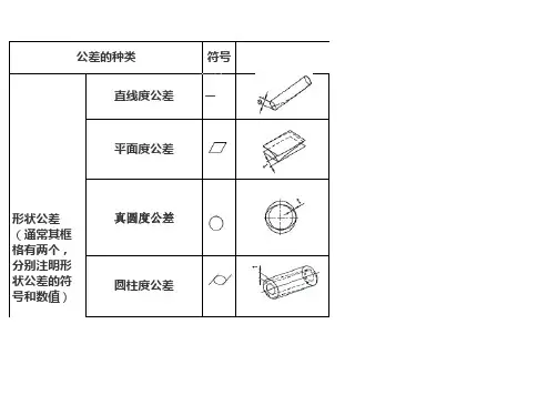
符号直线度公差—平面度公差真圆度公差圆柱度公差公差的种类形状公差(通常其框格有两个,分别注明形状公差的符号和数值)状公差的符号和数值)线的轮廓度公差面的轮廓度公差平行度公差定向公差垂直度公差倾斜度公差对称度位置度公差同轴度公差或同心度公差定位公差圆跳动公差跳动公差全跳动公差公差带的定义栏中使用的线含义如下:粗线或破折线:形体一点细线:中心线粗点线:基准二点细线:补充的投影面或截面细的实线或破折线:公差带二点粗线:物体在补充的投影面或截面的投影限制实际直线对理想直线直与不直的一项指标在表示公差带的数值前,如果有φ符号,则该公差带为直径t 的圆柱中之区域。
是限制实际平面对理想平面变动量的一项指标。
它是针对平面发生不平而提出的要求。
公差带是夹在间隔t的2个平行平面之间的区域。
是限制实际圆对理想圆变动量的一项指标。
它是对具有圆柱面(包括圆锥面、球面)的零件,在一正截面(与轴线垂直的面)内的圆形轮廓要求。
在圆度公差的标注中,箭头方向应垂直于轴线或指向圆心。
对象的平面内公差带为相隔t 的2个同心圆之间的区域。
限制实际圆柱面对理想圆柱面变动量的一项指标。
它控制了圆柱体横截面和轴截面内的各项形状误差,如圆度、素线直线度、轴线直线度等。
圆柱度是圆柱体各项形状误差的综合指标。
公差带为相隔t的2个同轴圆柱面之间的区域。
公差带的定义限制实际曲线对理想曲线变动量的一项指标。
它是对非圆曲线的形状精度要求。
公差带是指在理论上将中心放到正确的轮廓线上,以t作直径划圆时,两条包围线之间相夹的区域。
用来控制零件上被测要素(平面或直线)相对于基准要素(平面或直线)的方向偏离0°的要求,即要求被测要素对基准等距。
基准符号是用一粗短划线和带圆圈的字母标注,字母方向始终是正位,基准是中心要素时,粗短划线的引出线必须和有关尺寸线对齐.公差带是平行于基准平面,夹在相隔t的2个平行平面之间的区域。
用来控制零件上被测要素(平面或直线)相对于基准要素(平面或直线)的方向偏离90°的要求,即要求被测要素对基准成90°。
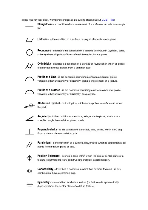
resources for your desk, workbench or pocket. Be sure to check out our GD&T Tips!Straightness - a condition where an element of a surface or an axis is a straightline.Flatness - is the condition of a surface having all elements in one plane.Roundness - describes the condition on a surface of revolution (cylinder, cone, sphere) where all points of the surface intersected by any plane.Cylindricity - describes a condition of a surface of revolution in which all points of a surface are equidistant from a common axis.Profile of a Line - is the condition permitting a uniform amount of profile variation, ether unilaterally or bilaterally, along a line element of a feature.Profile of a Surface - is the condition permitting a uniform amount of profile variation, ether unilaterally or bilaterally, on a surface.All Around Symbol - indicating that a tolerance applies to surfaces all around the part.Angularity - is the condition of a surface, axis, or centerplane, which is at a specified angle from a datum plane or axis.Perpendicularity - is the condition of a surface, axis, or line, which is 90 deg. From a datum plane or a datum axis.Parallelism - is the condition of a surface, line, or axis, which is equidistant at all points from a datum plane or axis.Position Tolerance - defines a zone within which the axis or center plane of a feature is permitted to vary from true (theoretically exact) position.Concentricity - describes a condition in which two or more features , in any combination, have a common axis.Symmetry - is a condition in which a feature (or features) is symmetrically disposed about the center plane of a datum feature.Runout - is the composite deviation from the desired form of a part surface of revolution through on full rotation (360 deg) of the part on a datum axis.Total Runout - is the simultaneous composite control of all elements of a surface at all circular and profile measuring positions as the part is rotated through 360.Maximum Material Condition (MMC) - is that condition of a part feature wherein it contains the maximum amount ofmaterial within the stated limits of size. That is: minimum hole size and maximum shaft size.Least Material Condition (LMC) - implies that condition of a part feature of size wherein it contains the least (minimum) amount of material, examples, largest hole size and smallest shaft size. It is opposite to maximum material condition.Regardless Of Feature Size (RFS) - the condition where the tolerance of form, runout or location must be met irrespective of where the feature lies within its size tolerance.Projected Tolerance Zone - applies to a hole in which a pin, stud, screw, etc., is to be inserted. It controls the perpendicularity of the hole to the extent of the projection from the hole and as it relates to the mating part clearance. The projected tolerance zone extends above the surface of the part to the functional length of the pin, stud, and screw relative to its assembly with the mating part.Tangent Plane - indicating a tangent plane is shown. The symbol is placed in the feature control frame following the stated tolerance.Free State Variations - is a term used to describe distortion of a part after removal of forces applied during manufacture.Diameter - indicates a circular feature when used on the field of a drawing or indicates that the tolerance is diametrical when used in a feature control frame.Basic Dimension - used to describe the exact size, profile, orientation or location of a feature. A basic dimension is always associated with a feature control frame or datum target. (Theoretically exact dimension in ISO)Reference Dimension - a dimension usually without tolerance, used for information purposes only. It does not govern production or inspection operations. (Auxiliary dimension in ISO)Datum Feature - is the actual component feature used to establish a datum.Dimension Origin - Signifies that the dimension originates from the plane established by the shorter surface and dimensional limits apply to the other surface.Feature Control Frame - is a rectangular boxcontaining the geometric characteristics symbol, andthe form, runout or location tolerance. If necessary,datum references and modifiers applicable to thefeature or the datums are also contained in the box.Conical Taper - is used to indicate taper for conical tapers. This symbol is always shown with the vertical leg to the left.Slope - is used to indicate slope for flat tapers. This symbol is always shown with the vertical leg to the left.Counterbore/Spotface - is used to indicate a counterbore or a spotface. The symbol precedes the dimension of the counterbore or spotface, with no spaceCountersink - is used to indicate a countersink. The symbol precedes the dimensions of the countersink with no space.Depth/Deep - is used to indicate that a dimension applies to the depth of a feature. This symbol precedes the depth value with no space in between.Square - is used to indicate that a single dimension applies to a square shape. The symbol precedes the dimension with no space between.Number of Places - the X is used along with a value to indicate the number of times a dimension or feature is repeated on the drawing.Arc Length - indicating that a dimension is an arc length measured on a curved outline. The symbol is placed above the dimension.Radius - creates a zone defined by two arcs (the minimum and maximum radii). The part surface must lie within this zone.Spherical Radius - precedes the value of a dimension or tolerance.Spherical Diameter - shall precede the tolerance value where the specified tolerance value represents spherical zone. Also, a positional tolerance may be used to control the location of a spherical feature relative to other features of a part. The symbol for spherical diameter precedes the size dimension of the feature and the positional tolerance value, to indicate a spherical tolerance zone.Controlled Radius - creates a tolerance zone defined by two arcs (the minimum and maximum radii) that are tangent to the adjacent surfaces. Where a controlled radius is specified, the part contour within the crescent-shaped tolerance zone must be a fair curve without flats or reversals. Additionally, radii taken at all points on the part contour shall neither be smaller than the specified minimum limit nor larger than the maximum limit.Between - to indicate that a profile tolerance applies to several contiguous features, letters may designate where the profile tolerance begins and ends. These letters are referenced using the between symbol (since 1994) or the word between on drawings made to earlier versions of the Standard.Statistical Tolerance - i s the assigning of tolerances to related components of an assembly on the basis of sound statistics (such as the assembly tolerance is equal to the square root of the sum of the squares of the individual tolerances). By applying statistical tolerancing, tolerances of individual components may be increased or clearances between mating parts may be reduced. The increased tolerance or improved fit may reduce manufacturing cost or improve the product's performance, but shall only be employed where the appropriate statistical process control will be used. Therefore, consideration should be given to specifying the required Cp and /or Cpk or other process performance indices.Datum Target - is a specified point, line, or area on a partthat is used to establish the Datum Reference Plane formanufacturing and inspection operations.Target Point - indicates where the datum target point is dimensionally located on the direct view of the surface.。
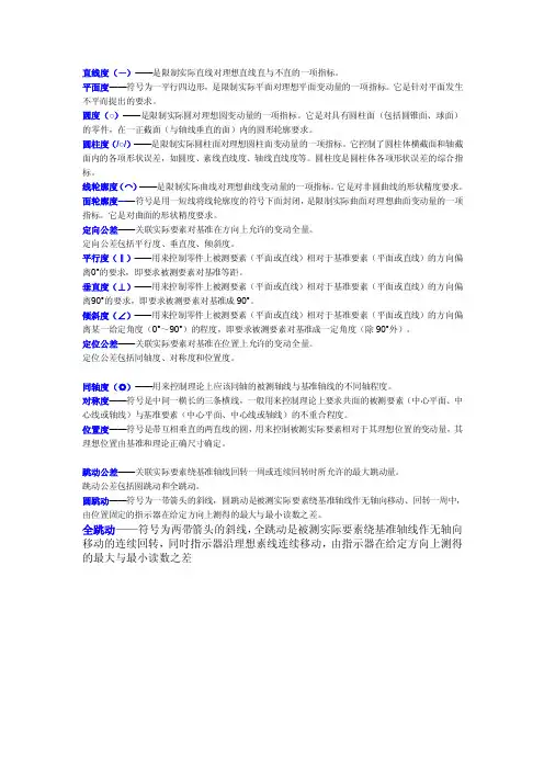
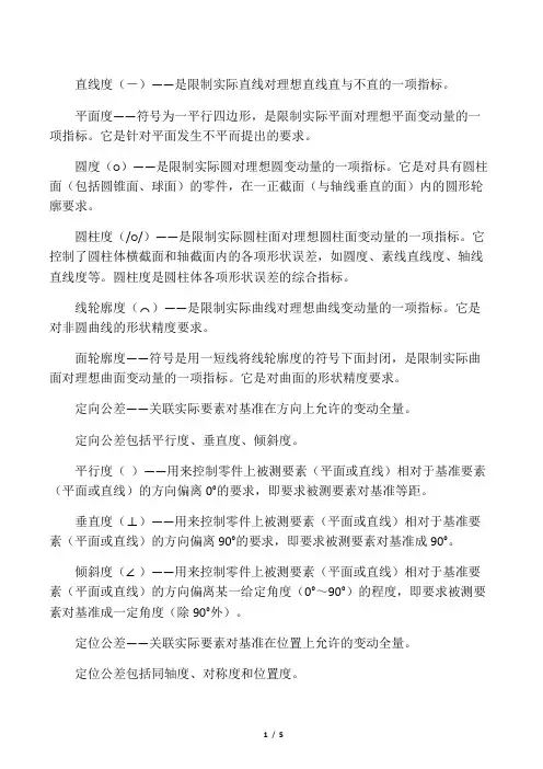
直线度(-)——是限制实际直线对理想直线直与不直的一项指标。
平面度——符号为一平行四边形,是限制实际平面对理想平面变动量的一项指标。
它是针对平面发生不平而提出的要求。
圆度(○)——是限制实际圆对理想圆变动量的一项指标。
它是对具有圆柱面(包括圆锥面、球面)的零件,在一正截面(与轴线垂直的面)内的圆形轮廓要求。
圆柱度(/○/)——是限制实际圆柱面对理想圆柱面变动量的一项指标。
它控制了圆柱体横截面和轴截面内的各项形状误差,如圆度、素线直线度、轴线直线度等。
圆柱度是圆柱体各项形状误差的综合指标。
线轮廓度(⌒)——是限制实际曲线对理想曲线变动量的一项指标。
它是对非圆曲线的形状精度要求。
面轮廓度——符号是用一短线将线轮廓度的符号下面封闭,是限制实际曲面对理想曲面变动量的一项指标。
它是对曲面的形状精度要求。
定向公差——关联实际要素对基准在方向上允许的变动全量。
定向公差包括平行度、垂直度、倾斜度。
平行度(‖)——用来控制零件上被测要素(平面或直线)相对于基准要素(平面或直线)的方向偏离0°的要求,即要求被测要素对基准等距。
垂直度(⊥)——用来控制零件上被测要素(平面或直线)相对于基准要素(平面或直线)的方向偏离90°的要求,即要求被测要素对基准成90°。
倾斜度(∠)——用来控制零件上被测要素(平面或直线)相对于基准要素(平面或直线)的方向偏离某一给定角度(0°~90°)的程度,即要求被测要素对基准成一定角度(除90°外)。
定位公差——关联实际要素对基准在位置上允许的变动全量。
定位公差包括同轴度、对称度和位置度。
同轴度(◎)——用来控制理论上应该同轴的被测轴线与基准轴线的不同轴程度。

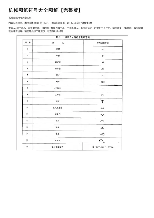
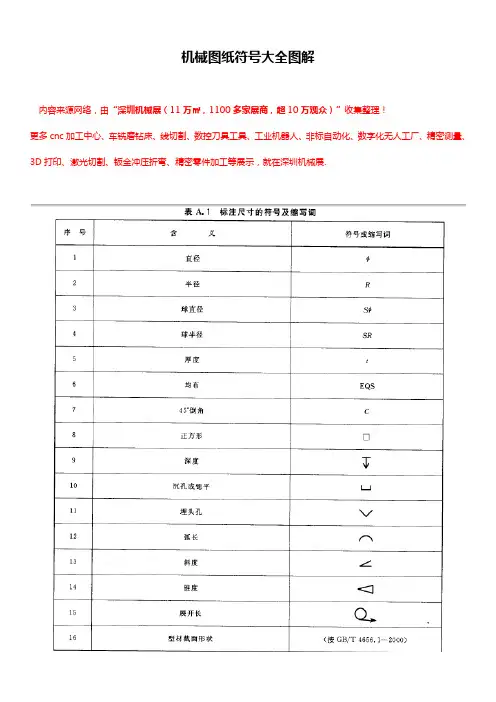
机械图纸符号⼤全图解【完整版】机械图纸符号⼤全图解内容来源⽹络,由“深圳机械展(11万㎡,1100多家展商,超10万观众)”收集整理!更多cnc加⼯中⼼、车铣磨钻床、线切割、数控⼑具⼯具、⼯业机器⼈、⾮标⾃动化、数字化⽆⼈⼯⼚、精密测量、3D打印、激光切割、钣⾦冲压折弯、精密零件加⼯等展⽰,就在深圳机械展.⼨时在尺⼨前⾯加注正⽅形符号。
⾼度h=3.5mm3GB/T4458.4-2003;标注弧长时在尺⼨前⾯加注弧长符号。
⾼度h=R=3.5mm4458.4-2003;16675.2-1996 尺⼨注法;沉孔或锪平符号。
⾼度h=3.5mm5 GB/T4458.4-2003;GB/T16675.2-1996 尺⼨注法;沉孔或锪平深度符号。
⾼度h=3.5mm6 GB/T4458.4-2003; GB/T16675.2-1996机械制图尺⼨标注常⽤标准符号序号符号名称符号绘制标准应⽤⽰例7 GB/T 15754-1995锥度符号或莫⽒锥度注法。
⾼度h=3.5mm8 JB/T 5061-2006定位⽀撑符号。
⾼度h=3.5mm9 JB/T 5061-2006辅助⽀撑符号。
⾼度h=3.5mm10 JB/T 5061-2006辅助⽀撑符号。
⾼度h=5mm11 GB/T 4459.5-1999中⼼孔符号。
⾼度h=3.5mm;⾼度H1=5mm。
汇编⼈:质管办标准化管理员郑家贵2011年8⽉25⽇机械制图基础知识⼀、.图线GB/T 4457.4-2002 GB/T 17450-1998注:粗虚线和粗点画线的选⽤(1)两种粗线都⽤来指⽰零件上的某⼀部分有特殊要求。
但应⽤场合不尽相同。
粗虚线专门⽤于指⽰该表⾯有表⾯处理要求。
(表⾯处理包括镀(涂)覆、化学处理和冷作硬化处理。
)(2)粗点画线是限定范围的表⽰线常见于以下场合:a.限定局部热处理的范围(如上图)b.限定不镀(涂)范围(如下左图)c.限定形位公差的被测要素和基准要素的范围(如下右图)⼆、视图GB/T 17451-1998 GB/T 4458.1-20021.按第⼀⾓法配置的六个基本视图2.局部视图1)按基本视图的配置形式配置2)按向视图的配置形式配置不要“向”字三、剖视图及剖⾯区域的表⽰法GB/T 17452~17453-1998 GB/T 4458.6-2002图形不对称时,移出断⾯不得画在中断处四、简化画法GB/T 16675.1-19961.管⼦1)可仅在端部画出部分形状,其余⽤细点画线画出其中⼼线2)可⽤与管⼦中⼼线重合的单根粗实线表⽰。
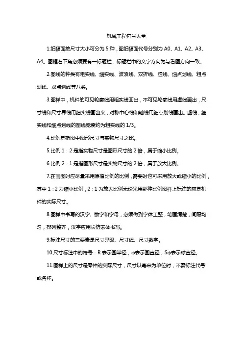
机械工程符号大全1.纸幅面按尺寸大小可分为5种,图纸幅面代号分别为A0、A1、A2、A3、A4。
图框右下角必须要有一标题栏,标题栏中的文字方向为与看图方向一致。
2.图线的种类有粗实线、细实线、波浪线、双折线、虚线、细点划线、粗点划线、双点划线等八类。
3.图样中,机件的可见轮廓线用粗实线画出,不可见轮廓线用虚线画出,尺寸线和尺寸界线用细实线画出来,对称中心线和轴线用细点划线画出。
虚线、细实线和细点划线的图线宽度约为粗实线的1/3。
4.比例是指图中图形尺寸与实物尺寸之比。
5.比例1:2是指实物尺寸是图形尺寸的2倍,属于缩小比例。
6.比例2:1是指图形尺寸是实物尺寸的2倍,属于放大比例。
7.在画图时应尽量采用原值比例的比例,需要时也可采用放大或缩小的比例,其中1:2为缩小比例,2:1为放大比例无论采用那种比例图样上标注的应是机件的实际尺寸。
8.图样中书写的汉字、数字和字母,必须做到字体工整,笔画清楚,间隔均匀,排列整齐,汉字应用长仿宋体书写。
9.标注尺寸的三要素是尺寸界限、尺寸线、尺寸数字。
10.尺寸标注中的符号:R表示圆半径,ф表示圆直径,Sф表示球直径。
11.图样上的尺寸是零件的实际尺寸,尺寸以毫米为单位时,不需标注代号或名称。
12.标准水平尺寸时,尺寸数字的字头方向应向上;标注垂直尺寸时,尺寸数字的字头方向应朝左。
角度的尺寸数字一律按水平位置书写。
当任何图线穿过尺寸数字时都必须断开。
13.斜度是指斜线对水平线的倾斜程度,用符号∠表示,标注时符号的倾斜方向应与所标斜度的倾斜方向一致。
所标锥度方向一致。
14.符号“∠1:10”表示斜度1:10,符号“1:5”表示锥度1:5。
15.平面图形中的线段可分为已知线段、中间线段、连接线段三种。
它们的作图顺序应是先画出已知线段,然后画中间线段,最后画连接线段。
16.已知定形尺寸和定位尺寸的线段叫已知线段;有定形尺寸,但定位尺寸不全的线段叫中间线段;只有定形尺寸没有定位尺寸的线段叫连接线段。
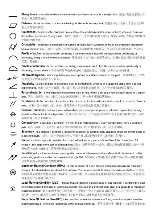
Straightness - a condition where an element of a surface or an axis is a straight line. 直线 - 表面元素或一个轴是一条直线的情况。
Flatness - is the condition of a surface having all elements in one plane. 平整度 - 是一个在一个平面上的所有元素的表面状况。
Roundness - describes the condition on a surface of revolution (cylinder, cone, sphere) where all points of the surface intersected by any plane. 圆度 - 描述了一个革命的表面(圆柱,圆锥,球体)表面各点的任何平面相交的条件。
Cylindricity - describes a condition of a surface of revolution in which all points of a surface are equidistant from a common axis.圆柱 - 描述了革命的表面,在表面所有点都是从一个共同的轴等距离的一个条件。
Profile of a Line - is the condition permitting a uniform amount of profile variation, ether unilaterally or bilaterally, along a line element of a feature. 线路简介- 允许统一轮廓的变化,乙醚单边或双边沿线的功能元素,是条件。
Profile of a Surface - is the condition permitting a uniform amount of profile variation, ether unilaterally or bilaterally, on a surface. - 表面轮廓是单边或双边统一的剖面变化,乙醚,表面上允许的条件。
机加工图纸符号大全机加工图纸是机械制造过程中不可或缺的一环,它是机械零部件加工的重要依据。
在机加工图纸中,各种符号的运用是至关重要的,因为它能够准确地传达设计意图,指导加工操作,保证产品的质量和精度。
本文将为大家详细介绍机加工图纸中常见的符号,希望能够帮助大家更好地理解和运用机加工图纸。
1. 尺寸标注符号。
在机加工图纸中,尺寸标注是非常重要的一环,它能够直观地告诉加工人员零件的尺寸大小。
常见的尺寸标注符号包括直径标注符号(Φ)、长度标注符号(L)、宽度标注符号(W)等。
这些符号的准确运用能够有效地指导加工操作,确保零件的尺寸精度。
2. 表面质量标注符号。
表面质量对于机械零部件的功能和外观都有着重要的影响,因此在机加工图纸中,表面质量标注符号也是不可或缺的。
常见的表面质量标注符号包括光洁度标注符号(Ra)、粗糙度标注符号(Rz)等。
这些符号能够清晰地表达对零件表面质量的要求,指导加工人员进行相应的加工操作。
3. 加工工艺符号。
在机加工图纸中,加工工艺符号能够直观地告诉加工人员零件的加工工艺和方法。
常见的加工工艺符号包括钻孔符号(Φ)、镗孔符号(Φ)、铣削符号(Φ)等。
这些符号能够有效地指导加工人员选择合适的加工工艺,确保零件的加工质量。
4. 材料标注符号。
材料对于机械零部件的性能和用途都有着重要的影响,因此在机加工图纸中,材料标注符号也是必不可少的。
常见的材料标注符号包括材料牌号标注符号(如45#、20Cr等)、材料种类标注符号(如钢材、铝合金等)。
这些符号能够清晰地告诉加工人员零件所选用的材料,指导后续的材料采购和加工操作。
5. 其他辅助标注符号。
除了上述几种常见的符号外,机加工图纸中还有许多其他辅助标注符号,如装配标注符号、公差标注符号等。
这些符号能够进一步完善图纸的信息,提供更多的加工和装配指导。
总结:机加工图纸符号是机械制造过程中不可或缺的一部分,它能够准确地传达设计意图,指导加工操作,保证产品的质量和精度。
直线度(-)——是限制实际直线对理想直线直与不直的一项指标。
平面度——符号为一平行四边形,是限制实际平面对理想平面变动量的一项指标。
它是针对平面发生不平而提出的要求。
圆度(○)——是限制实际圆对理想圆变动量的一项指标。
它是对具有圆柱面(包括圆锥面、球面)的零件,在一正截面(与轴线垂直的面)内的圆形轮廓要求。
圆柱度(/○/)——是限制实际圆柱面对理想圆柱面变动量的一项指标。
它控制了圆柱体横截面和轴截面内的各项形状误差,如圆度、素线直线度、轴线直线度等。
圆柱度是圆柱体各项形状误差的综合指标。
线轮廓度(⌒)——是限制实际曲线对理想曲线变动量的一项指标。
它是对非圆曲线的形状精度要求。
面轮廓度——符号是用一短线将线轮廓度的符号下面封闭,是限制实际曲面对理想曲面变动量的一项指标。
它是对曲面的形状精度要求。
定向公差——关联实际要素对基准在方向上允许的变动全量。
定向公差包括平行度、垂直度、倾斜度。
平行度(‖)——用来控制零件上被测要素(平面或直线)相对于基准要素(平面或直线)的方向偏离0°的要求,即要求被测要素对基准等距。
垂直度(⊥)——用来控制零件上被测要素(平面或直线)相对于基准要素(平面或直线)的方向偏离90°的要求,即要求被测要素对基准成90°。
倾斜度(∠)——用来控制零件上被测要素(平面或直线)相对于基准要素(平面或直线)的方向偏离某一给定角度(0°~90°)的程度,即要求被测要素对基准成一定角度(除90°外)。
定位公差——关联实际要素对基准在位置上允许的变动全量。
定位公差包括同轴度、对称度和位置度。
同轴度(◎)——用来控制理论上应该同轴的被测轴线与基准轴线的不同轴程度。
对称度——符号是中间一横长的三条横线,一般用来控制理论上要求共面的被测要素(中心平面、中心线或轴线)与基准要素(中心平面、中心线或轴线)的不重合程度。
位置度——符号是带互相垂直的两直线的圆,用来控制被测实际要素相对于其理想位置的变动量,其理想位置由基准和理论正确尺寸确定。
机械工程符号案例讲解小伙伴们!今天咱们来唠唠机械工程符号那些事儿,通过一些超有趣的案例,让你轻松搞懂它们。
一、粗糙度符号。
比如说,你看到一个零件表面,有的地方光滑得像镜子,有的地方却有点粗糙。
这时候,粗糙度符号就闪亮登场啦。
有这么一个小例子啊。
假如你要做一个金属小盒子,这个盒子的外面呢,是要拿来展示的,那肯定希望它看起来高大上,表面滑溜溜的。
这时候在机械工程图纸上,就会用一个特定的粗糙度符号来表示这个要求。
这个符号就像是一个小魔法标记,告诉加工的师傅:“师傅,这个面要加工得很光滑哦,粗糙度得达到这个标准。
”这个粗糙度符号长啥样呢?它有点像一个小勾,上面还带着一些数字和字母啥的。
数字呢,就是告诉你这个表面到底要多光滑或者多粗糙的具体数值啦。
就像你给厨师说你要几分熟的牛排一样精确。
二、形位公差符号。
再来说说形位公差符号,这个听起来有点高大上,但其实理解起来也不难。
想象一下,你在搭积木,要把一个小圆柱准确无误地放在一个圆形的小洞里。
这个小圆柱的形状和它在洞里的位置得非常精准才行,不然整个“积木大厦”就不稳啦。
在机械工程里也是一样的道理。
比如说有个轴要装进一个孔里,这个轴可不能是歪歪扭扭的,它的形状得是直的,而且要正好在孔的中心位置。
这时候,形位公差符号就来规定这个要求啦。
有个平行度的符号,就像两条平行的小斜线。
如果在轴和孔的图纸上看到这个符号,就是在说:“喂,加工的时候要注意啦,这个轴和孔的某个面得保持平行关系哦,偏差可不能太大。
”还有垂直度符号,就像一个小L加上一个圆圈啥的。
这就是告诉工人师傅,这个零件的两个面得是垂直的关系,就像墙角一样,不能有太大的倾斜。
三、基准符号。
基准符号就像是机械世界里的“标准参考点”。
打个比方,你在画一幅画,总得有个起点或者参考线吧,不然画出来的东西就乱套了。
在机械工程里,基准符号就是这个作用。
比如说一个复杂的机械部件,由好几个小零件组成。
其中一个零件是其他零件安装的基础,那这个零件上就会标上基准符号。
机械制图多个六角形标注符号
在机械制图中,使用的六角形标注符号主要有以下几种:
1. 六边形外框:用于将相同特性的图形或元件分组标记,通常使用字母或数字作为标识符,例如A、B、C等。
2. 单向箭头:用于指示图纸上的某个位置或方向,通常用于指示装配关系、运动方向或连接方式等。
3. 双向箭头:用于指示双向运动或连接关系,例如泛指的配对螺纹的位置等。
4. 带文本的六边形:用于标注重要或特殊要求,例如材料要求、表面处理要求、尺寸要求等。
请注意,这里所提及的六角形标注符号仅为机械制图中常见的几种,具体使用情况还需要根据实际设计要求和相关标准进行判断。