起重机论文中英文资料外文翻译文献
- 格式:docx
- 大小:21.11 KB
- 文档页数:12
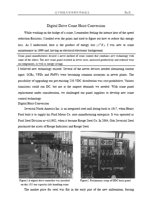
Digital Drive Crane Hoist ConversionWhile working on the bridge of a crane, I remember feeling the intense heat of the speed reduction Resistors. I looked over the prints and tried to figure out how to reduce this energy loss. As I understood, heat is the product of energy lost (R I 2). I was new to crane maintenance in 1990 and, having an electrical/electronic background,Crane panel manufacturers desired a novel method of crane control that combines new technology with some of the oldest. The new crane panel resulted in lower costs, increased productivity and reduced wear on components, as well as energy savings.I believed new technology existed. Several of the newer devices needed alternating current input. SCRs, VFDs and PMWs were becoming common acronyms in newer plants. The possibility of upgrading our pre-existing 250 VDC distribution was cost-prohibitive, Various transistors could run DC, but not at the ampere demands we needed. With crane panel replacement under consideration, we challenged our panel suppliers to develop new crane control technologyDigital Hoist ConversionSeverstal North America Inc. is an integrated steel mill dating back to 1917, when Henry Ford built it to supply his Ford Motor Co. auto manufacturing enterprise. It was operated as Ford Steel Division ur~ti11982, when it became Rouge Steel Co. In 2004, OAt Severstal Steel purchased the assets of Rouge Industries and Rouge Steel.Figure1.A digital drive controller was installed Figure2. Preliminary setup of DDC hoist panel on this 135-ton-capacity slab-handling craneThe market price for steel was flat in the early part of the new millennium, forcingdepartmental groups to look for cost-saving improvements. One improvement was the installation of a new type of digital electronic control panel in 2003. This panel represented the introduction of DC electronic crane control to Rouge Steel and the largest duplex crane hoist controller (dual 200-hp) of its type in North America.The original panels were built on a P&H 135-ton slab-handling crane having standard DC hoisting contactor controls. They were industrial and functional, designed to handle the loads of this crane in 1972. The loads are greater now with heavier slabs, runing the crane at maximum limits and higher production rates. This caused premature equipment failures and production down-time. With three aging cranes in this bay, maintenance costs were rising to new highs. Those involved in maintenance were finding that distributors and manufactures were downsizing or had gone out of business, making replacement parts costly or obsolete. The market drivers of today are forcing the change to newer technologiesFigure3. Digital panel installed on crane trolley deck Figure4.Prewired resistors reduced start-uptimeA novel design approach was asked of the crane panel manufactures. They replied with a proposed partnership and an effort to add some of the newest technology to the oldest methods of crane controls. The result was high-current transistor switching with a 250 VDC input. The design was well-thought-out and included integrating the original motors, limits, switches and wiring. Now speeds are controlled by sending the motors only enough current to safely lift and lower the load. The motors are soft stopped (reverse plugged) before the brakesclose. This saves wear on components, reduces costs and increases productivity. Without the need for reduction resistors, there is no energy wasted, maximizing the energy savings. The panel installation of the SY-4 crane was completed in 2003 and is still running. The results are smoother movements with little energy loss (heat).The new panels were designed for installation on the trolley deck, as opposed to the bridge deck.. This aids in troubleshooting and reduces excessive wiring mainly at the weak point of the cable powertrack.. This allowed the time and ability to perform all setup work during mini-downturns without disabling the original hoist. The original panel was left in place as a backup, as failures could not be predicted. To date, the fail-safe panel has not been required.The panels were pre-wired and pre-tested prior to crane installation, further reducing crane downtime. When the transfer day came, only the master switch, motors and limit leads needed to be rerouted to the new system. On-the-job tuning and monitoring were vital for the first couple of days. It was important to have crane operators involved for that “personal feel”and to obtain their buy-in to the project, to increase awareness and productivity. No-load and full-load current tests were run with great results.An aded benefit to this control is the electrical current savings. Without reductin resistors for speed points, and with the added benefit of power produced when regenerative lowering, this single crane installation saves more than $25000 in electricity annually. This can be a very important consideration if substation power is near critical usage levels. The demand this system imposes is much less than a similar contactor system. With energy costs on the rise, this is a concern for every project considered. Figure 5 indicates an example of electrical current savings potential by comparing contactor panel loads(top) to digital drive loads(bottom).How it works in the circuit is not unique. The insulated gate bipolar transistor(IGBT) takes the place of the contactors and acceleration resistors. As the master switch is selected for greater speed, the circuitry triggers the transistor at a frequency(pulse width modulated) that allows current to flow through the IGBT. The current circulates in the standard series armature and series field along with the series brake. The longer the input is turned on, thehigher the output average voltage (Figure 6). The higher the voltage, the higher the horsepower produced. This system can provide high torque with low currents(heat) as the result of motor regenerative properties. High speed with no load can also be accomplished. Much of this could not be achieved with the original panels.Figure5.Example of energy saved during lowering sequence.The difference is noticed when the IGBT is in its off cycle(Figure 7). In this instance, the motor acts as a generator, producing circulating currents through the flyback diode and maintaining self-induced motor currents. This effect reduces ripple and provides current that was not provided by the original power source. The reduction of current loads on system feeders and hardware further adds to the total savings package.The following items are important considerations when determining if this system will work with an application.IGBTs are the newest part of the design that makes this panel work with 250 volts DC. They combine the advantages of the bipolar transistor(high voltage and current) with the advantages of the metal oxide semiconductor field effect transistor(MOSFET)(low power consumtion and high switching). IGBTs are semiconductors that combine a high voltage and high current bipolar junction transistor(BJT) with a low-power and fast-switching MOSFET. Consequently, IGBTs provide faster speeds and better drive and output characteristics than power transistors and offer higher current capabilities than equivalent high-powered transistors.Figure6.Hoist current flow when the IGBT is onFigure7.Hoist continuing motor current flow when the IGBT is off.Heat sinking, including consideration of air temperature and air flow, is essential to the proper operation of any solid-state reply. It is necessary to rovide an effective means of removing heat from the IGBT. The importance of using a proper heat sink cannot be overstressed, since it directly affects the maximum usable load current and maximum allowable ambient temperature. Up to 90 percent of the problems with transistors are directly related to heat. Lack of attention to this detail can result in improper switching(lockup) or even total destruction of the IGBT. If the device ever reaches an internal temperature of 105℃, it will be permanently destroyed. One of the problems encountered at Severstal NA was program temperature cutbacks due to excessive heating. When electrical current cutback does not control the drive, it will stop on software limits. Transistors develop heat as a result of a forward voltage drop through the junction of the IGBT. Beyond this point, heat will cause a reduction(software cutback) of the load current that can be handled. If the demand is too great,the program is designed to shut down.Care must be taken when mounting solid-state relays(SSRs) in a confined area. SSRs should be mounted on individual heat sinks whenever possible. SSRs should never be operated without proper heat sinking or in free air, as they will thermally self-destruct under load. A simple way to monitor temperature is to slip a thermocouple under a mounting screw. If the base temperature does not exceed 45℃, the SSR is operating at its optimal level. Remember that the heatsink removes the heat from the SSR and transfers that heat to the air in the electrical enclosure. In turn, this air must circulate and transfer its heat to the outside ambient. Vents and forced ventilation are good ways to accomplish this. Semiconductor fuses are the only reliable way to protect SSRs. They are also referred to as current-limiting fuses, providing extremely fast opening while restricting let-through current far below the fault current that could destroy the semiconductor. This type of fuse tends to be expensive, but cheap by comparison to the damage that could occur, providing a means of fully protecting SSRs against high current overloads. An RI2fuse rating is useful in aiding in the proper design of SSR fusing. This rating is the benchmark for an SSR's ability to handle a shorted output condition. Devices such as circuit breakers and slow blowfuses cannot react quickly enough to protect the SSR in a shorted condition and are not recommended. Every SSR has an I2rating. The idea is to select a fuse matching the capability of the solid-state relay for the Tsame duration.Figure8.IGBT and components mounted on heat Figure9.External mounted fans removed IGBT heatFigure10. Panel fans removed internal heat buildup Figure11. Semiconductor fuses provide the bestprotection for solid-state relays Motor switching and dynamic loads, such as motors and solenoids, can create special problems for SSPs. High initial surge current is drawn because its star t-up impedance is usually very low. As a motor rotates, it develops a counter electromotive force (CEMF) that resists the flow of currenL This CEMF can also add to the applied line voltage and create over-voltage conditions during turn-off and regenerative times. It should be noted that over-voltage caused by inductive voltage doubling or CEMF from the motor cannot be effectively dealt with by adding voltage-transient suppressors. Suppressors such as metal oxide varistors (MOVs) are typically designed for brief high-voltage spikes and may be destroyed by sustained hlgh-energy conduction. V oltage dump resistors may be needed in extreme cases and should be engineered to meet a system's demand, It is therefore important that SSRa are chosen to withstand the highest expected sustained voltage.Problems encountered while running the200-hp dual drive were few hut worth mentioning. The program allows for setdng many variables (i.e., speed, currents, brake-open voltage). Most of these are detrimental to the drive or motor if set incorrectly. Although staying within the drive specifications is safe, this may not produce the desired actions. Ambient temperatures must also be considered, since most useful application are near higher-temperature areas. Following are several problems(and solutions) observed during installation and trials:Problem 1:The first problem presented itself when applying excessive brake-open curent.The direction contactors were flashed and pitted. Also, the emergency brake contactor appears bluish from high heat. Reducing brake-open current and power-on time to a shorter duration solved the problem.●Problem 2:Hall effect transistors and IGBT were thought to be faulty parts and/or wiring, but this could not be duplicated. Many suspect parts were replaced, but it was determined that internal panel ambient temperature was the problem. This was solved with cooling fans on the doors and on the IGBT cooling fins.●Problem 3:Temperature cutbacks usually led to errors. It was found that a new crane operator did not like operating the hoist at full speed. Longer run time and higher IGBT cycles caused unnecessary heating in panels. Reducing field current settings eased this problem. This increased the lowering speeds but greatly reduced the IGBT voltage drop, in turn reducing its heat dissipation. Cooling fans eliminated the problem.●Problem 4:All power must be disconnected from the line because all lines feed from a common bus capacitive filtering system. This means that the typical way of “pulling motor disconnect and running the controls only”to troubleshoot does not work. The panel diagnostics and troubleshooting information provided is very helpful.●Problem 5:Lack of electronic knowledge by the electricians is a concern. When production downtime is critical, the time to troubleshoot is a high-priced commodity. This ultimately puts pressure on the electricians, causing frustration. The solutions was to ensure that the crew is involved Mth project design and installation. Training is vital. If the maintenance team is nat up to speed with the technology, failure is probable. Two training classes were held for all electrical team members.After one year, the actual materials maintenance and labor savings were calculated, with a payback of 6.2 months. Cost savings and efficiency gains were greater than expected. This led the way to the next drive conversion, which was scheduled for 2006. With a cooperative effort by salespersons, manufacturers, engineers and end-users, Severstal NA vastly improved its ability to compete successfully.AcknowledgmentsThe author would like to acknowledge the efforts of former general supervisor FredSchwartz and the crew at Severstal North America. Without their help, the project may never have gotten this far.References1. Creech, R., 'Energy Savings -- DC Digital and DC Contactor Hoist Control System," Iron ~ Steel Technotogg, May 2005, pp. 225-228.2. /modval/database/contents/reports/igbt.html3. /computing/unix/software/matlab/toolbox/powersys/igbt.html4. /old_pdf/app_ notes/r_ipm.pdf5. /access/helpdesk_r13/help/toolbox/physmod/powersys/igbt.html数字机起重机提升转换虽然工作在桥上的吊车,我记得感觉酷热的速度减少电阻.我看着图纸,并试图弄清楚如何减少这种能源损失.正如我的理解一样,热是产品的能源损失(RI2)。
起重机文献翻译高考翻译机械翻译国内双钩同步起吊电动葫芦发展综述Development Overview of Domestic Double-hook Synchronous Hoisting Electric Hoist于晓东1吴英年2Y u Xiaodong1Wu Yingnian2摘要:分析了国内生产的几种双钩同步电动葫芦结构与功能,重点介绍了HT型双钩同步电动葫芦的功能特点与应用,指出了产品研制应创新使其具有长远生命力。
Abstract:This paper analyzes the structures and functions of several domestic-made double-hook synchronous hoisting electric hoists, emphasizes the function and characteristics of HI type double-hook synchronous hoisting electric hoist and points out that product development should be innovative as to make long-term vitality.关键词:双钩同步电动葫芦;功能;结构;应用;发展Keywords: double-hook synchronous hoisting electric hoist; function; structure; application; development2.起重机用钢丝绳标准的选择Crane Wire Ropes Standard Selection陈立Chen Li3.斗轮堆取料机在头部激振下的动态响应Dynamic Response of Bucket Wheel Stacker Reclaimer underHead Shock Excitation王俊华张光宇高翔孔涛Wang Junhua Zhang Guangyu Gao Xiang Kong Tao摘要:分析斗轮堆取料机的实际工程特点,对其进行有限元建模并进行模态和谐响应分析,以了解斗轮堆取料机轮斗头部在滚筒或斗轮激振力作用下垂直方向的动态特性。
机床的论文中英文资料外文翻译文献引言机床是制造业中重要的设备,用于加工各种零部件和制造产品。
本文汇总了关于机床的论文中英文资料的外文翻译文献,以供参考和研究使用。
外文翻译文献列表Author: John Smith John SmithYear: 2015 20152. Title: Advanced Techniques for Machine Tool Analysis Title: Advanced Techniques for Machine Tool AnalysisAuthor: Jennifer Lee Jennifer LeeYear: 2016 20163. Title: Intelligent Control Systems for Precision Machining Title: Intelligent Control Systems for Precision MachiningAuthor: David Wang David WangYear: 2018 2018Abstract: This paper focuses on intelligent control systems for precision machining. It discusses the integration of artificial intelligence and control algorithms to enhance the precision and performance of machine tools. The paper presents case studies on the application of intelligent control systems in precision machining processes. This paper focuses on intelligent control systems for precision machining. It discusses the integration of artificial intelligence and control algorithms to enhance the precision and performance of machine tools. The paper presents case studies on the application of intelligent control systems in precision machining processes.4. Title: Advances in Machining Processes for Hard-to-Machine Materials Title: Advances in Machining Processes for Hard-to-Machine MaterialsAuthor: Emily Chen Emily ChenYear: 2019 2019Abstract: This paper reviews recent advances in machining processes for hard-to-machine materials. It discusses the challenges associated with machining materials such as titanium, nickel-basedalloys, and ceramics. The paper highlights the development of new cutting tools, machining strategies, and technologies to improve the machinability of these materials. This paper reviews recent advances in machining processes for hard-to-machine materials. It discusses the challenges associated with machining materials such as titanium, nickel-based alloys, and ceramics. The paper highlights the development of new cutting tools, machining strategies, and technologies to improve the machinability of these materials.5. Title: Optimization of Machining Parameters for Energy Efficiency Title: Optimization of Machining Parameters for Energy EfficiencyAuthor: Michael Liu Michael LiuYear: 2020 2020Abstract: This paper explores the optimization of machining parameters for energy efficiency. It discusses the impact of machining parameters, such as cutting speed, feed rate, and depth of cut, on energy consumption in machining processes. The paper presents optimization techniques and case studies on reducing energy consumption in machining operations. This paper explores theoptimization of machining parameters for energy efficiency. It discusses the impact of machining parameters, such as cutting speed, feed rate, and depth of cut, on energy consumption in machining processes. The paper presents optimization techniques and case studies on reducing energy consumption in machining operations.结论以上是关于机床的论文中英文资料的外文翻译文献,希望对研究和了解机床技术的人员有所帮助。
Selection calculation of the monorail hoist in coal mineZHUANG YanAbstract:This paper introduces the applicable conditions and the selection calculation of the monorail hoistbriefly, and pointe out its application characteristics. This provides the reasonable selection of the monorailhoist with the necessary theoretical basis.Keywords:monorail hoist; applicable condition; computing method; characteristicsMonorail crane is used in coal mine, especially in mining area up, down and down the mountain. Auxiliary equipment for transporting materials, equipment and personnel in working face drift. One of the preparations. Monorail crane can be divided into steel wire according to different traction modes. Rope traction and locomotive traction can be divided into two categories, and locomotive traction mode can be divided into two categories. There are two types of locomotive traction: explosion-proof clean diesel locomotive and battery locomotive. General information. The monorail crane trains for material, equipment and personnel transportation are composed of 3. When transporting heavy equipment, only one group consists of two groups. The load-bearing vehicle for lifting the composite beam.1 applicable conditions of monorail crane(1) Monorail crane is hanging on the roadway roof or support to transport negative load. It is not affected by floor deformation (floor heave) and material accumulation in roadway. A reliable hanging bearing device is required. Hanging on arched or trapezoidal steel support. When the support is mounted on the scaffold, itshall be reinforced with braces. When the anchor rod is used for suspension, each hanger shall be used. Two bolts with anchoring force of more than 60 kn shall be used for rail point. Roadway fault. The surface should be greater than or equal to 7 m2.(2) It can be used for horizontal and inclined roadway transportation. For inclined roadway. When transportation, the locomotive traction monorail crane, gradient ≤ 18 degrees, the best use. The slope is less than 12 degrees (the maximum is 40 degrees in foreign countries). Rope traction monorail crane gradient ≤25 ° and 45 ° in foreign countries. The maximum single piece transport mass is 12-15t. The minimum horizontal radius of curvature is 4 M.(3) Locomotive traction monorail crane has the characteristics of mobility and flexibility. Each locomotive can realize the transportation of materials, equipment and personnel in multiple branch roadways. Transportation, can not be reprinted, not limited by the distance. Monorail with rope traction. The crane needs to install a large number of rope pulleys on the curve, and can not enter the branch. The transportation distance is generally 1-2 km, and the maximum is not more than 3 km. Because of luck Long distance, train running resistance, traction rope resistance, track and support. The bearing capacity of the monorail, the guide wire rope and the. The tension of wire rope will tend to be complicated.(4) There is a small amount of pollution and difference in the exhaust gas of diesel monorail crane. Therefore, the use of roadway should have enough air volume to dilute harmful gas. Body, so as to achieve the degree of non-destructive health.(5) The biggest advantage of battery monorail crane is no air pollution. However, limited by the storage capacity of the battery, the battery monorail crane is difficult tooperate. It is suitable for low traction and ventilation. Poor tunnelling for transporting materials and personnel.2 selection calculation of monorail craneThe main content of monorail crane selection calculation includes the selection of monorail crane. The type of winch, the calculation of the actual traction force, the choice of winch or diesel. Calculation of daily transportation capacity of single monorail crane and determination of mining area. Or the number of monorail cranes required by the whole mine.2.1 selection of monorail crane type(1)The necessary known conditions for monorail crane calculation are: ①transportation distance. The results show that: 1) the distance between the running track and the running track; 2) the gradient of the running tunnel; 3) whether the running track has branches; 4) the distance between the running track and the running track. The maximum mass of the single piece to be transported;5)whether to transport personnel.(2)According to the known conditions and the applicability of the above monorail cranes. Around, choose wire rope traction monorail crane or diesel monorail crane (also Explosion proof special type battery monorail crane can be selected.)2.2 calculation of traction and power of monorail craneIn order to calculate the traction force of monorail crane, the monorail cranemust be determined first. The single maximum transportation volume of the vehicle, that is, the production volume served by the monorail crane is calculated. Point to material and equipment requirements. The calculation should be based on the quality of the material. The weight of each transport unit is 3 T, That is: 1) the transportation volume of each container is 2.5 T, and 3.5 t without container t. (2) materials less than 3.1 m in length are transported in containers, and those more than 3.1 m in length are transported in containers .M.General Monorail.Generally, the monorail crane only hangs 3-4 lifting beams at a time, that is to transport one beam. Each train can only transport 3-4 tons of materials, equipment and personnel each time. Transportation unit (or 3-4 people vehicles); transport large equipment such as hydraulic support. When erecting, the monorail crane can only hang one combined lifting beam. Monorail hanging train. The total mass of the vehicle is g, and the payload is Q. according to the above three conditions, the. The maximum value of (Q + G) is taken to calculate the traction force.(1) Calculation of traction forceF=(Q+G)g /1000η B (µcosα+g sin α)(1)Where: F is the traction force of monorail crane, kn; G is the total mass of monorail Quantity, kg; q is the payload, kg; μ is the ru nning resistance of monorail crane. Coefficient, μ = 0.3; α is roadway dip angle, (°); η B is line efficiency, When the line is a straight line, η B = 0.8, and η b decreases by 0.01 for every 15 ° increase in horizontal curve.The traction force of winch or diesel locomotive is selected according to f value, and the latter needs to be adjusted, Slightly larger than the former.(2) Calculation of motor power. The shaft power n of traction winch can be calculated according to the following formulaN=F v/η A (2)Where: V is the running speed, v = 2 m / S; η A is the driving device efficiency 75.According to the n value, select the motor capacity n standard, n standard ≥ n.2.3 selection calculation of wire rope for monorail crane with wire rope tractionThe traction winch of monorail crane is hydraulic friction winch with steel wire rope Closed loop.Its transmission principle is friction transmission, and the tension on both sides of the large friction wheel is FY And FL. The relationship between the two can be expressed by Euler's formula, that isF y=Fl eµα(3)Where: FY Is the tension at the point where the wire rope meets the friction wheel, kn; fl by. Tension at the separation point of wire rope and friction wheel, kn; μ is the tension between wire rope and friction wheel. Friction factor between wheels, μ = 0.1; α is the friction factor of wire rope on friction wheel. The envelop angle is α = 5 and π = 900 degrees.(1) Tension calculation of wire rope at winch separation pointBecause f = FY - FL = fl(E μ α - 1), so the wire rope is in the winch. The minimum tension fl min at the separation point of the friction wheel can be calculated by the following formulaFl min=F/ (eµα -1)n (4)Where: n is the friction reserve coefficient, n = 1.15-1.2.(2) Calculation of breaking force of wire rope. The breaking force FB of wire rope can be calculated according to the following formulaFB=Q+G ─── 1 000 g ma sin α 。
起重机中英⽂对照外⽂翻译⽂献中英⽂对照外⽂翻译(⽂档含英⽂原⽂和中⽂翻译)Control of Tower Cranes WithDouble-Pendulum Payload DynamicsAbstract:The usefulness of cranes is limited because the payload is supported by an overhead suspension cable that allows oscilation to occur during crane motion. Under certain conditions, the payload dynamics may introduce an additional oscillatory mode that creates a double pendulum. This paper presents an analysis of this effect on tower cranes. This paper also reviews a command generation technique to suppress the oscillatory dynamics with robustness to frequency changes. Experimental results are presented to verify that the proposed method can improve the ability of crane operators to drive a double-pendulum tower crane. The performance improvements occurred during both local and teleoperated control.Key words:Crane , input shaping , tower crane oscillation , vibrationI. INTRODUCTIONThe study of crane dynamics and advanced control methods has received significant attention. Cranes can roughly be divided into three categories based upontheir primary dynamic properties and the coordinate system that most naturally describes the location of the suspension cable connection point. The first category, bridge cranes, operate in Cartesian space, as shown in Fig. 1(a). The trolley moves along a bridge, whose motion is perpendicular to that of the trolley. Bridge cranes that can travel on a mobile base are often called gantry cranes. Bridge cranes are common in factories, warehouses, and shipyards.The second major category of cranes is boom cranes, such as the one sketched in Fig. 1(b). Boom cranes are best described in spherical coordinates, where a boom rotates aboutaxes both perpendicular and parallel to the ground. In Fig. 1(b), ψis the rotation aboutthe vertical, Z-axis, and θis the rotation about the horizontal, Y -axis. The payload is supported from a suspension cable at the end of the boom. Boom cranes are often placed on a mobile base that allows them to change their workspace.The third major category of cranes is tower cranes, like the one sketched in Fig. 1(c). These are most naturally described by cylindrical coordinates. A horizontal jib arm rotates around a vertical tower. The payload is supported by a cable from the trolley, which moves radially along the jib arm. Tower cranes are commonly used in the construction of multistory buildings and have the advantage of having a small footprint-to-workspace ratio. Primary disadvantages of tower and boom cranes, from a control design viewpoint, are the nonlinear dynamics due to the rotational nature of the cranes, in addition to the less intuitive natural coordinate systems.A common characteristic among all cranes is that the pay- load is supported via an overhead suspension cable. While this provides the hoisting functionality of the crane, it also presents several challenges, the primary of which is payload oscillation. Motion of the crane will often lead to large payload oscillations. These payload oscillations have many detrimental effects including degrading payload positioning accuracy, increasing task completion time, and decreasing safety. A large research effort has been directed at reducing oscillations. An overview of these efforts in crane control, concentrating mainly on feedback methods, is provided in [1]. Some researchers have proposed smooth commands to reduce excitation of system flexible modes [2]–[5]. Crane control methods based on command shaping are reviewed in [6]. Many researchers have focused on feedback methods, which necessitate the addition necessitate the addition of sensors to the crane and can prove difficult to use in conjunction with human operators. For example, some quayside cranes have been equipped with sophisticated feedback control systems to dampen payload sway. However, the motions induced by the computer control annoyed some of the human operators. As a result, the human operators disabled the feedback controllers. Given that the vast majority of cranes are driven by human operators and will never be equipped with computer-based feedback, feedback methods are not considered in this paper.Input shaping [7], [8] is one control method that dramatically reduces payload oscillation by intelligently shaping the commands generated by human operators [9], [10]. Using rough estimates of system natural frequencies and damping ratios, a series of impulses, called the input shaper, is designed. The convolution of the input shaper and the original command is then used to drive the system. This process is demonstrated with atwo-impulse input shaper and a step command in Fig. 2. Note that the rise time of the command is increased by the duration of the input shaper. This small increase in the rise time isnormally on the order of 0.5–1 periods of the dominant vibration mode.Fig. 1. Sketches of (a) bridge crane, (b) boom crane, (c) and tower crane.Fig. 2. Input-shaping process.Input shaping has been successfully implemented on many vibratory systems including bridge [11]–[13], tower [14]–[16], and boom [17], [18] cranes, coordinate measurement machines[19]–[21], robotic arms [8], [22], [23], demining robots [24], and micro-milling machines [25].Most input-shaping techniques are based upon linear system theory. However, some research efforts have examined the extension of input shaping to nonlinear systems [26], [14]. Input shapers that are effective despite system nonlinearities have been developed. These include input shapers for nonlinear actuator dynamics, friction, and dynamic nonlinearities [14], [27]–[31]. One method of dealing with nonlinearities is the use of adaptive or learning input shapers [32]–[34].Despite these efforts, the simplest and most common way to address system nonlinearities is to utilize a robust input shaper [35]. An input shaper that is more robust to changes in system parameters will generally be more robust to system nonlinearities that manifest themselves as changes in the linearized frequencies. In addition to designing robust shapers, input shapers can also be designed to suppress multiple modes of vibration [36]–[38].In Section II, the mobile tower crane used during experimental tests for this paper is presented. In Section III, planar and 3-D models of a tower crane are examined to highlight important dynamic effects. Section IV presents a method to design multimode input shapers with specified levels of robustness. InSection V, these methods are implemented on a tower crane with double-pendulum payload dynamics. Finally, in Section VI, the effect of the robust shapers on human operator performance is presented for both local and teleoperated control.II. MOBILE TOWER CRANEThe mobile tower crane, shown in Fig. 3, has teleoperation capabilities that allow it to be operated in real-time from anywhere in the world via the Internet [15]. The tower portion of the crane, shown in Fig. 3(a), is approximately 2 m tall with a 1 m jib arm. It is actuated by Siemens synchronous, AC servomotors. The jib is capable of 340°rotation about the tower. The trolley moves radially along the jib via a lead screw, and a hoisting motor controls the suspension cable length. Motor encoders are used for PD feedback control of trolley motion in the slewing and radial directions. A Siemens digital camera is mounted to the trolley and records the swing deflection of the hook at a sampling rate of 50 Hz [15].The measurement resolution of the camera depends on the suspension cable length. For the cable lengths used in this research, the resolution is approximately 0.08°. This is equivalent to a 1.4 mm hook displacement at a cable length of 1 m. In this work, the camera is not used for feedback control of the payload oscillation. The experimental results presented in this paper utilize encoder data to describe jib and trolley position and camera data to measure the deflection angles of the hook. Base mobility is provided by DC motors with omnidirectional wheels attached to each support leg, as shown in Fig. 3(b). The base is under PD control using two HiBot SH2-based microcontrollers, with feedback from motor-shaft-mounted encoders. The mobile base was kept stationary during all experiments presented in this paper. Therefore, the mobile tower crane operated as a standard tower crane.Table I summarizes the performance characteristics of the tower crane. It should be noted that most of these limits areenforced via software and are not the physical limitations of the system. These limitations are enforced to more closely match theoperational parameters of full-sized tower cranes.Fig. 3. Mobile, portable tower crane, (a) mobile tower crane, (b) mobile crane base.TABLE I MOBILE TOWER CRANE PERFORMANCE LIMITSFig. 4 Sketch of tower crane with a double-pendulum dynamics.III. TOWER CRANE MODELFig.4 shows a sketch of a tower crane with a double-pendulum payload configuration. The jib rotates by an angle around the vertical axis Z parallelto the tower column. The trolley moves radially along the jib; its position along the jib is described by r . The suspension cable length from the trolley to the hook is represented by an inflexible, massless cable of variable length 1l . The payload is connected to the hook via an inflexible, massless cable of length 2l . Both the hook and the payload are represented as point masses having masses h m and p m , respectively.The angles describing the position of the hook are shown in Fig. 5(a). The angle φrepresents a deflection in the radial direction, along the jib. The angle χ represents a tangential deflection, perpendicular to the jib. In Fig. 5(a), φ is in the plane of the page, and χ lies in a plane out of the page. The angles describing the payload position are shown in Fig. 5(b). Notice that these angles are defined relative to a line from the trolley to the hook. If there is no deflection of the hook, then the angleγ describes radial deflections, along the jib, and the angle α represents deflections perpendicular to the jib, in the tangential direction. The equations of motion for this model were derived using a commercial dynamics package, but they are too complex to show in their entirety here, as they are each over a page in length.To give some insight into the double-pendulum model, the position of the hook and payload within the Newtonian frame XYZ are written as —h q and —p q , respectivelyWhere -I , -J and -K are unit vectors in the X , Y , and Z directions. The Lagrangian may then be written asFig. 5. (a) Angles describing hook motion. (b) Angles describing payload motion.Fig. 6. Experimental and simulated responses of radial motion.(a) Hook responses (φ) for m 48.01=l ,(b) Hook responses for m 28.11=lThe motion of the trolley can be represented in terms of the system inputs. The position of the trolley —tr q in the Newtonian frame is described byThis position, or its derivatives, can be used as the input to any number of models of a spherical double-pendulum. More detailed discussion of the dynamics of spherical double pendulums can be found in [39]–[42].The addition of the second mass and resulting double-pendulum dramatically increases the complexity of the equations of motion beyond the more commonly used single-pendulum tower model [1], [16], [43]–[46]. This fact can been seen in the Lagrangian. In (3), the terms in the square brackets represent those that remain for the single-pendulum model; no —p q terms appear. This significantly reduces the complexity of the equations because —p q is a function of the inputs and all four angles shown in Fig. 5.It should be reiterated that such a complex dynamic model is not used to design the input-shaping controllers presented in later sections. The model was developed as a vehicle to evaluate the proposed control method over a variety of operating conditions and demonstrate its effectiveness. The controller is designed using a much simpler, planar model.A. Experimental V erification of the ModelThe full, nonlinear equations of motion were experimentally verified using several test cases. Fig.6 shows two cases involving only radial motion. The trolley was driven at maximum velocity for a distance of 0.30 m, with 2l =0.45m .The payload mass p m for both cases was 0.15 kg and the hook mass h m was approximately 0.105 kg. The two cases shown in Fig. 6 present extremes of suspension cable lengths 1l . In Fig. 6(a), 1l is 0.48 m , close to the minimum length that can be measured by the overhead camera. At this length, the double-pendulum effect is immediately noticeable. One can see that the experimental and simulated responses closely match. In Fig. 6(b), 1l is 1.28 m, the maximum length possible while keeping the payload from hitting the ground. At this length, the second mode of oscillation has much less effect on the response. The model closely matches the experimental response for this case as well. The responses for a linearized, planar model, which will be developed in Section III-B, are also shown in Fig. 6. The responses from this planar model closely match both the experimental results and the responses of the full, nonlinear model for both suspension cable lengths.Fig. 7. Hook responses to 20°jib rotation:(a) φ (radial) response;(b) χ (tangential) response.Fig. 8. Hook responses to 90°jib rotation:φ(radial) response;(b) χ(tangential) response.(a)If the trolley position is held constant and the jib is rotated, then the rotational and centripetal accelerations cause oscillation in both the radial and tangential directions. This can be seen in the simulation responses from the full nonlinear model in Figs. 7 and 8. In Fig. 7, the trolley is held at a fixed position of r = 0.75 m, while the jib is rotated 20°. This relatively small rotation only slightly excites oscillation in the radial direction, as shown in Fig. 7(a). The vibratory dynamics are dominated byoscillations in the tangential direction, χ, as shown in Fig. 7(b). If, however, a large angular displacement of the jib occurs, then significant oscillation will occur in both the radial and tangential directions, as shown in Fig. 8. In this case, the trolley was fixed at r = 0.75 m and the jib was rotated 90°. Figs. 7 and 8 show that the experimental responses closely match those predicted by the model for these rotational motions. Part of the deviation in Fig. 8(b) can be attributed to the unevenness of the floor on which the crane sits. After the 90°jib rotation the hook and payload oscillate about a slightly different equilibrium point, as measured by the overhead camera.Fig.9.Planardouble-pendulummodel.B.Dynamic AnalysisIf the motion of the tower crane is limited to trolley motion, like the responses shown in Fig. 6, then the model may be simplified to that shown in Fig. 9. This model simplifies the analysis of the system dynamics and provides simple estimates of the two natural frequencies of the double pendulum. These estimates will be used to develop input shapers for the double-pendulum tower crane.The crane is moved by applying a force )(t u to the trolley. A cable of length 1l hangs below the trolley and supports a hook, of mass h m , to which the payload is attached using rigging cables. The rigging and payload are modeled as a second cable, of length 2l and point mass p m . Assuming that the cable and rigging lengths do not change during the motion, the linearized equations of motion, assuming zero initial conditions, arewhere φ and γ describe the angles of the two pendulums, R is the ratio of the payload mass to the hook mass, and g is the acceleration due to gravity.The linearized frequencies of the double-pendulum dynamics modeled in (5) are [47]Where Note that the frequencies depend on the two cable lengths and the mass ratio.Fig. 10. Variation of first and second mode frequencies when m l l 8.121=+.。
附录外文文献原文:The Introduction of cranesA crane is defined as a mechanism for lifting and lowering loads with a hoisting mechanism Shapiro, 1991. Cranes are the most useful and versatile piece of equipment on a vast majority of construction projects. They vary widely in configuration, capacity, mode of operation, intensity of utilization and cost. On a large project, a contractor may have an assortment of cranes for different purposes. Small mobile hydraulic cranes may be used for unloading materials from trucks and for small concrete placement operations, while larger crawler and tower cranes may be used for the erection and removal of forms, the installation of steel reinforcement, the placement of concrete, and the erection of structural steel and precast concrete beams.On many construction sites a crane is needed to lift loads such as concrete skips, reinforcement, and formwork. As the lifting needs of the construction industry have increased and diversified, a large number of general and special purpose cranes have been designed and manufactured. These cranes fall into two categories, those employed in industry and those employed in construction. The most common types of cranes used in construction are mobile, tower, and derrick cranes.1.Mobile cranesA mobile crane is a crane capable of moving under its own power without being restricted to predetermined travel. Mobility is provided by mounting or integrating the crane with trucks or all terrain carriers or rough terrain carriers or by providing crawlers. Truck-mounted cranes have the advantage of being able to move under their own power to the construction site. Additionally, mobile cranes can move about the site, and are often able to do the work of several stationary units.Mobile cranes are used for loading, mounting, carrying large loads and for work performed in the presence of obstacles of various kinds such as power lines and similar technological installations. The essential difficulty is here the swinging of the payload which occurs during working motion and also after the work is completed. This applies particularly to the slewing motion of the crane chassis, for which relatively large angular accelerations and negative accelerations of the chassis are characteristic. Inertia forces together with the centrifugal force and the Carioles force cause the payload to swing as a spherical pendulum. Proper control of the slewing motion of the crane serving to transport a payload to the defined point with simultaneous minimization of the swings when theworking motion is finished plays an important role in the model.Modern mobile cranes include the drive and the control systems. Control systems send the feedback signals from the mechanical structure to the drive systems. In general, they are closed chain mechanisms with flexible members [1].Rotation, load and boom hoisting are fundamental motions the mobile crane. During transfer of the load as well as at the end of the motion process, the motor drive forces, the structure inertia forces, the wind forces and the load inertia forces can result in substantial, undesired oscillations in crane. The structure inertia forces and the load inertia forces can be evaluated with numerical methods, such as the finite element method. However, the drive forces are difficult to describe. During start-up and breaking the output forces of the drive system significantly fluctuate. To reduce the speed variations during start-up and braking the controlled motor must produce torque other than constant [2,3], which in turn affects the performance of the crane.Modern mobile cranes that have been built till today have oft a maximal lifting capacity of 3000 tons and incorporate long booms. Crane structure and drive system must be safe, functionary and as light as possible. For economic and time reasons it is impossible to build prototypes for great cranes. Therefore, it is desirable to determinate the crane dynamic responses with the theoretical calculation.Several published articles on the dynamic responses of mobile crane are available in the open literature. In the mid-seventies Peeken et al. [4] have studied the dynamic forces of a mobile crane during rotation of the boom, using very few degrees of freedom for the dynamic equations and very simply spring-mass system for the crane structure. Later Maczynski et al. [5] studied the load swing of a mobile crane with a four mass-model for the crane structure. Posiadala et al. [6] have researched the lifted load motion with consideration for the change of rotating, booming and load hoisting. However, only the kinematics were studied. Later the influence of the flexibility of the support system on the load motion was investigated by the same author [7]. Recently, Kilicaslan et al. [1] have studied the characteristics of a mobile crane using a flexible multibody dynamics approach. Towarek [16] has concentrated the influence of flexible soil foundation on the dynamic stability of the boom crane. The drive forces, however, in all of those studies were presented by using so called the metho d of ……kinematics forcing‟‟ [6] with assumed velocities or accelerations. In practice this assumption could not comply with the motion during start-up and braking.A detailed and accurate model of a mobile crane can be achieved with the finite element method. Using non-linear finite element theory Gunthner and Kleeberger [9] studied the dynamic responses of lattice mobile cranes. About 2754 beam elements and 80 truss elements were used for modeling of the lattice-boom structure. On this basis a efficient software for mobile crane calculation––NODYA has been developed. However, the influences of the drive systems must be determined by measuring on hoisting of the load[10], or rotating of the crane [11]. This is neither efficient nor convenient for computer simulation of arbitrary crane motions.Studies on the problem of control for the dynamic response of rotary crane are also available. Sato et al. [14], derived a control law so that the transfer a load to a desired position will take place that at the end of the transfer of the swing of the load decays as soon as possible. Gustafsson [15] described a feedback control system for a rotary crane to move a cargo without oscillations and correctly align the cargo at the final position. However, only rigid bodies and elastic joint between the boom and the jib in those studies were considered. The dynamic response of the crane, for this reason, will be global.To improve this situation, a new method for dynamic calculation of mobile cranes will be presented in this paper. In this method, the flexible multibody model of the steel structure will be coupled with the model of the drive systems. In that way the elastic deformation, the rigid body motion of the structure and the dynamic behavior of the drive system can be determined with one integrated model. In this paper this method will be called ……complete dynamic calculation for driven “mechanism”.On the basis of flexible multibody theory and the Lagrangian equations, the system equations for complete dynamic calculation will be established. The drive- and control system will be described as differential equations. The complete system leads to a non-linear system of differential equations. The calculation method has been realized for a hydraulic mobile crane. In addition to the structural elements, the mathematical modeling of hydraulic drive- and control systems is decried. The simulations of crane rotations for arbitrary working conditions will be carried out. As result, a more exact representation of dynamic behavior not only for the crane structure, but also for the drive system will be achieved. Based on the results of these simulations the influences of the accelerations, velocities during start-up and braking of crane motions will be discussed.2.Tower cranesThe tower crane is a crane with a fixed vertical mast that is topped by a rotating boom and equipped with a winch for hoisting and lowering loads (Dickie, 990). Tower cranes are designed for situations which require operation in congested areas. Congestion may arise from the nature of the site or from the nature of the construction project. There is no limitation to the height of a high-rise building that can be constructed with a tower crane. The very high line speeds, up to 304.8 mrmin, available with some models yield good production rates at any height. They provide a considerable horizontal working radius, yet require a small work space on the ground (Chalabi, 1989). Some machines can also operate in winds of up to 72.4 km/h, which is far above mobile crane wind limits.The tower cranes are more economical only for longer term construction operations and higher lifting frequencies. This is because of the fairly extensive planning needed for installation, together with the transportation, erection and dismantling costs.3. Derrick cranesA derrick is a device for raising, lowering, and/or moving loads laterally. The simplest form of the derrick is called a Chicago boom and is usually installed by being mounted to building columns or frames during or after construction (Shapiro and Shapiro, 1991).This derrick arrangement. (i.e., Chicago boom) becomes a guy derrick when it is mounted to a mast and a stiff leg derrick when it is fixed to a frame.The selection of cranes is a central element of the life cycle of the project. Cranes must be selected to satisfy the requirements of the job. An appropriately selected crane contributes to the efficiency, timeliness, and profitability of the project. If the correct crane selection and configuration is not made, cost and safety implications might be created (Hanna, 1994). Decision to select a particular crane depends on many input parameters such as site conditions, cost, safety, and their variability. Many of these parameters are qualitative, and subjective judgments implicit in these terms cannot be directly incorporated into the classical decision making process. One way of selecting crane is achieved using fuzzy logic approach.Cranes are not merely the largest, the most conspicuous, and the most representative equipment of construction sites but also, at various stages of the project, a real “bottleneck” that slows the pace of the construction process. Although the crane can be found standing idle in many instances, yet once it is involved in a particular task ,it becomes an indispensable link in the activity chain, forcing at least two crews(in the loading and the unloading zones) to wait for the service. As analyzed in previous publications [6-8] it is feasible to automate (or, rather, semi-automate) crane navigation in order to achieve higher productivity, better economy, and safe operation. It is necessary to focus on the technical aspects of the conversion of existing crane into large semi-automatic manipulators. By mainly external devices mounted on the crane, it becomes capable of learning, memorizing, and autonomously navigation to reprogrammed targets or through prêt aught paths.The following sections describe various facets of crane automation:First, the necessary components and their technical characteristics are reviewed, along with some selection criteria. These are followed by installation and integration of the new components into an existing crane. Next, the Man –Machine –Interface (MMI) is presented with the different modes of operation it provides. Finally, the highlights of a set of controlled tests are reported followed by conclusions and recommendations.Manual versus automatic operation: The three major degrees of freedom of common tower cranes are illustrated in the picture. In some cases , the crane is mounted on tracks , which provide a fourth degree of freedom , while in other cases the tower is “telescope” or extendable , and /or the “jib” can be raised to a diagonal position. Since these additional degrees of freedom are not used routinely during normal operation but rather are fixed in a certain position for long periods (days or weeks), they are not included in the routineautomatic mode of operation, although their position must be “known” to the control system.外文文献中文翻译:起重机介绍起重机是用来举升机构、抬起或放下货物的器械。
本科毕业设计(论文)外文翻译译文题目:使用智能液压缸增加起重机的稳定性学院:机电学院专业:机械设计制造及其自动化学生:XXX学号:1234567890指导教师:XXX完成时间:2017年3月12日From:Hitchcox, Alan. Smart cylinders stabilize cranes[J]. Hydraulics & Pneumatics; Cleveland (Sep 12, 2013): n/a.Smart cylinders stabilize cranesHitchcox, Alan.ASM International, Penton Media, OTP Industrial Solutions(formerly Ohio Transmission & Pump Co)Abstract:It's not unusual for cranes to reach 100 ft or more into the air at major construction sites. Traditionally, cranes are transported to a work area and assembled on-site. More recently, as truck-mounted cranes bee bigger and more powerful, they have found favor because they are quicker to set up than traditional cranes. Truck-mounted cranes have a telescoping hydraulic boom mounted on mercial truck chassis. Their portability and lower setup costs have led to their widespread use at construction and utility sites around the world. But as loads get heavier and lifting distances bee higher, designers of truck-mounted cranes must provide the stability to ensure that safety remains the top priority.Truck-mounted cranes use outrigger systems to ensure stable operation. The outriggers extend from the main body of the truck and contact the ground several feet away from the truck. This distributes the crane's load over a much larger area, thereby increasing stability. Manitowoc pany Inc., Manitowoc, Wis., takes this a step further by using smart cylinders in the A-frame outrigger systems of its National Crane line of truck-mounted cranes. The crane's hydraulic system is driven from a power takeoff on the truck's transmission. The crane operator then runs all crane functions through a series of lever-operated valves at a control station.The ELA is an externally mounted LDT that uses Hall-effect technology to sense the location of a magnet embedded in the cylinder's piston through the cylinder's carbon steel barrel. A microprocessor then assigns an analog voltage to the magnet's corresponding absolute position. For example, when the cylinder is fully retracted; the voltage may be 0.55 V. As the cylinder extends, the voltage gradually increases until 4.5 V is reached at full extension.Accuracy of the transducer is typically +-0.5 mm (0.02 in.) - more than adequate for most mobile equipment. That position is then sent to the ECM and pared to the known maximum horizontal extension. After this, an indication is given to the operator about the outrigger state. The position update happens within milliseconds.Full TextIt's not unusual for cranes to reach 100 ft or more into the air at major construction sites. Traditionally, cranes are transported to a work area and assembled on-site. More recently, as truck-mounted cranes bee bigger and more powerful, they have found favor because they are quicker to set up than traditional cranes. Truck-mounted cranes have a telescoping hydraulic boom mounted on mercial truck chassis. Their portability and lower setup costs have led to their widespread use at construction and utility sites around the world. But as loads get heavier and lifting distances bee higher, designers of truck-mounted cranes must provide the stability to ensure that safety remains the top priority.Truck-mounted cranes use outrigger systems to ensure stable operation. The outriggers extend from the main body of the truck and contact the ground several feet away from the truck. This distributes the crane's load over a much larger area, thereby increasing stability. Manitowoc pany Inc., Manitowoc, Wis., takes this a step further by using smart cylinders in the A-frame outrigger systems of its National Crane line of truck-mounted cranes. The crane's hydraulic system is driven from a power takeoff on the truck's transmission. The crane operator then runs all crane functions through a series of lever-operated valves at a control station.An important function for lifting, moving, and lowering heavy loads is to ensure that outrigger beams are properly positioned. The outriggers are attached to the truck frame and are extended downward by hydraulic cylinders at an angle to create an A-frame structure that is wider at its base than at the top. This provides a stable framework to level and support the loaded and extended crane.Adding smarts to outriggersFor the past several years, National Crane has added outrigger-monitoring systems (OMSs) to its cranes. With the OMS, operators monitor the horizontal extension of the crane's outriggers at a control station. The OMS used with A-frame model cranes includes an ELA position-sensing linear-displacement transducer (LDT) from Rota Engineering, Dallas, anelectronic control module (ECM), and bicolor indication LEDs at each station.The ELA is an externally mounted LDT that uses Hall-effect technology to sense the location of a magnet embedded in the cylinder's piston through the cylinder's carbon steel barrel. A microprocessor then assigns an analog voltage to the magnet's corresponding absolute position. For example, when the cylinder is fully retracted; the voltage may be 0.55 V. As the cylinder extends, the voltage gradually increases until 4.5 V is reached at full extension. Accuracy of the transducer is typically +-0.5 mm (0.02 in.) - more than adequate for most mobile equipment. That position is then sent to the ECM and pared to the known maximum horizontal extension. After this, an indication is given to the operator about the outrigger state. The position update happens within milliseconds.Mark Hoffman, of Rota Engineering, pointed out that because mobile equipment has a human operator, position feedback from cylinders generally only needs to be within hundredths of an inch. Put simply, he says that magnetostrictive LDTs are overkill for most mobile-equipment applications. He suggests that an LDT with slightly less precision, but substantially lower cost, would enable designers to provide cylinder position feedback more often - not just for the most critical applications that justify high cost.Simple electronic displayThe electronic control module on the A-frame units serves only to monitor the position of the outriggers and provide feedback to the operator. As the analog voltage from the ELA transducer is read into the ECM, it sends a signal to a set of bicolor LEDs - one set per operator's station. The indications available are:Red for system error (sensor out of range, electrical short, etc.).Blinking red to indicate the operator is not at a valid working position as directed by the operation manual.Green to inform the operator that full horizontal extension has been acplished. The ECM can be configured through the use of a service tool to also help diagnose any issues related to the OMS.Made for mobileDesigned for use with mobile equipment, the ELA transducer matches this application well because of several physical and intrinsic attributes. The most important of these is the ability to mount the sensor along the exterior of the hydraulic outrigger-cylinder barrel. Although thecylinder gains added functionality, in many cases it retains the same form and fit as the original cylinder; the smart cylinder is essentially a drop-in replacement. The envelope in which the cylinder is mounted does not change. Only additional harnessing and the ECM are added - plus there are minor physical changes to the rear stabilizers.The cylinder bores used in A-frame outriggers range from 3 to 4.5 in. Strokes may be as long as of 66.9 in., depending on lifting capacity. According to Hoffman added, "Eliminating the expense of gun-drilling the piston rod and machining the end cap reduces the cost of creating this smart cylinder. The cylinder's structural integrity remains the same, and it is easier to assemble, install, and service than cylinders with magnetostrictive sensors."Other positive attributes: the Hall-effect sensor is noncontact for long service life, its temperature rating is high, it performs well in high shock and vibration applications, and its aluminum housing resists damage from impact and corrosion. The external transducer can be replaced in the field without difficulty.Cylinders can be supplied with magnets already fitted, so that if the stroke-sensing function is required later, the transducer can easily be added. The magnet assembly for the EL transducer is designed to match the bore of the cylinder. A slot is milled into the piston to acmodate the magnet assembly. Service life is not a factor because the magnet assembly is made of the same quality as piston-wear rings.A different kind of linear sensorModel ELA linear-displacement transducers (LDTs) use Hall-effect technology and mount externally to mobile hydraulic cylinders. Unlike other types of in-cylinder LDTs, they can be used in double-ended cylinders. They can also be used effectively in steering and long-stroke cylinders, where gun drilling can bee cost prohibitive and are easily field replaceable.Hall-effect LDTs can be manufactured for strokes exceeding 50 ft and for use 20,000 ft below the surface of the ocean and other demanding environments.Hall-effect technologyLDTs from Rota Engineering use a microprocessor that transmits and receives signals from Hall-effect chips mounted to a printed-circuit board. The circuit board is contained within a stainless-steel or aluminum housing, depending on application requirements. A piston-mounted magnet causes a voltage drop when it passes over the Hall-effect chip. The microprocessor calculates the position of the Hall-effect chip and correlates the voltage drop toa proportional voltage, current, PWM, or CANbus output.Hoffman explains, "Hall-effect sensors do not have as high a resolution as magnetostrictive sensors, which can achieve resolution measured in ten-thousandths of an inch. Hall-effect LDTs, however, generally have resolution of 0.012 to 0.020 in. The tighter resolution of magnetostrictive LDTs is needed for many process applications, such as a rolling mill. Most of the time, though, 0.020-in. resolution is more than sufficient for mobile hydraulic applications."An additional benefit of the Hall-effect technology is small size. In most instances, the pin-to-pin dimension of a cylinder need not be increased to acmodate a Hall-effect LDT. Also, the surface-mount technology tolerates high levels of vibration, and potting can provide additional vibration resistance.For more information, contact Rota Engineering at (972) 359-1041, or visit .rota-eng.. For information on Manitowoc's truck-mounted cranes and other products, visit .manitowoc.译自:希契科克斯,艾伦. 使用智能液压缸增加起重机的稳定性[J]. 液压与气动技术;克利夫兰(2013年9月12日):n/a使用智能液压缸增加起重机的稳定性希契科克斯,艾伦ASM国际片通媒体,OTP工业解决方案(以前俄亥俄州传输和泵)摘要:在大型的建筑工地上起重机将重物举至空中100英尺及以上的情况并不罕见。
The History of Crane1.OverviewThe first construction cranes were invented by the Ancient Greeks and were powered by men or beasts of burden, such as donkeys. These cranes were used for the construction of tall buildings. Larger cranes were later developed, employing the use of human treadwheels, permitting the lifting of heavier weights. In the High Middle Ages, harbor cranes were introduced to load and unload ships and assist with their construction – some were built into stone towers for extra strength and stability. The earliest cranes were constructed from wood, but cast iron and steel took over with the coming of the Industrial Revolution.For many centuries, power was supplied by the physical exertion of men or animals, although hoists in watermills and windmills could be driven by the harnessed natural power. The first 'mechanical' power was provided by steam engines, the earliest steam crane being introduced in the 18th or 19th century, with many remaining in use well into the late 20th century. Modern cranes usually use internal combustion engines or electric motors and hydraulic systems to provide a much greater lifting capability than was previously possible, although manual cranes are still utilized where the provision of power would be uneconomic.Cranes exist in an enormous variety of forms – each tailored to a specific use. Sizes range from the smallest jib cranes, used inside workshops, to the tallest tower cranes, used for constructing high buildings. For a while, mini - cranes are also used for constructing high buildings, in order to facilitate constructions by reaching tight spaces. Finally, we can find larger floating cranes, generally used to build oil rigs and salvage sunken ships. This article also covers lifting machines that do not strictly fit the above definition of a crane, but are generally known as cranes, such as stacker cranes and loader cranes.2. History(1)Ancient GreeceThe crane for lifting heavy loads was invented by the Ancient Greeks in the late 6th century BC. The archaeological record shows that no later than c.515 BC distinctive cuttings for both lifting tongs and lewis irons begin to appear on stone blocks of Greek temples. Since these holes point at the use of a lifting device, and since they are to be found either above the center of gravity of the block, or in pairs equidistant from a point over the center of gravity, they are regarded by archaeologists as the positive evidence required for the existence of the crane.The introduction of the winch and pulley hoist soon lead to a widespread replacement of ramps as the main means of vertical motion. For the next two hundred years, Greek building sites witnessed a sharp drop in the weights handled, as the new lifting technique made the use of several smaller stones more practical than of fewer larger ones. In contrast to the archaic period with its tendency to ever-increasing block sizes, Greek temples of the classical age like the Parthenon invariably featured stone blocks weighing less than 15-20 tons. Also, the practice of erecting large monolithic columns was practically abandoned in favor of using several column drums.Although the exact circumstances of the shift from the ramp to the crane technology remain unclear, it has been argued that the volatile social and political conditions of Greece were moresuitable to the employment of small, professional construction teams than of large bodies of unskilled labor, making the crane more preferable to the Greek polis than the more labor-intensive ramp which had been the norm in the autocratic societies of Egypt or Assyria.The first unequivocal literary evidence for the existence of the compound pulley system appears in the Mechanical Problems (Mech. 18, 853a32-853b13) attributed to Aristotle (384-322 BC), but perhaps composed at a slightly later date. Around the same time, block sizes at Greek temples began to match their archaic predecessors again, indicating that the more sophisticated compound pulley must have found its way to Greek construction sites by then.Ancient RomeThe heyday of the crane in ancient times came during the Roman Empire, when construction activity soared and buildings reached enormous dimensions. The Romans adopted the Greek crane and developed it further. We are relatively well informed about their lifting techniques, thanks to rather lengthy accounts by the engineers Vitruvius (De Architectura 10.2, 1-10) and Heron of Alexandria (Mechanica 3.2-5). There are also two surviving reliefs of Roman treadwheel cranes, with the Haterii tombstone from the late first century AD being particularly detailed.The simplest Roman crane, the Trispastos, consisted of a single-beam jib, a winch, a rope, and a block containing three pulleys. Having thus a mechanical advantage of 3:1, it has been calculated that a single man working the winch could raise 150 kg (3 pulleys x 50 kg = 150), assuming that 50 kg represent the maximum effort a man can exert over a longer time period. Heavier crane types featured five pulleys (Pentaspastos) or, in case of the largest one, a set of three by five pulleys (Polyspastos) and came with two, three or four masts, depending on the maximum load. The Polyspastos, when worked by four men at both sides of the winch, could already lift 3000 kg (3 ropes x 5 pulleys x 4 men x 50 kg = 3000 kg). In case the winch was replaced by a treadwheel, the maximum load even doubled to 6000 kg at only half the crew, since the treadwheel possesses a much bigger mechanical advantage due to its larger diameter. This meant that, in comparison to the construction of the Egyptian Pyramids, where about 50 men were needed to move a 2.5 ton stone block up the ramp (50 kg per person), the lifting capability of the Roman Polyspastos proved to be 60 times higher (3000 kg per person).However, numerous extant Roman buildings which feature much heavier stone blocks than those handled by the Polyspastos indicate that the overall lifting capability of the Romans went far beyond that of any single crane. At the temple of Jupiter at Baalbek, for instance, the architrave blocks weigh up to 60 tons each, and one corner cornice block even over 100 tons, all of them raised to a height of about 19 m. In Rome, the capital block of Trajan's Column weighs 53.3 tons, which had to be lifted to a height of about 34 m (see construction of Trajan's Column).It is assumed that Roman engineers lifted these extraordinary weights by two measures (see picture below for comparable Renaissance technique): First, as suggested by Heron, a lifting tower was set up, whose four masts were arranged in the shape of a quadrangle with parallel sides, not unlike a siege tower, but with the column in the middle of the structure (Mechanica 3.5). Second, a multitude of capstans were placed on the ground around the tower, for, although having a lower leverage ratio than treadwheels, capstans could be set up in higher numbers and run by more men (and, moreover, by draught animals). This use of multiple capstans is also described by AmmianusMarcellinus (17.4.15) in connection with the lifting of the Lateranense obelisk in the Circus Maximus (ca. 357 AD). The maximum lifting capability of a single capstan can be established by the number of lewis iron holes bored into the monolith. In case of the Baalbek architrave blocks, which weigh between 55 and 60 tons, eight extant holes suggest an allowance of 7.5 ton per lewis iron, that is per capstan. Lifting such heavy weights in a concerted action required a great amount of coordination between the work groups applying the force to the capstans.Middle AgesDuring the High Middle Ages, the treadwheel crane was reintroduced on a large scale after the technology had fallen into disuse in western Europe with the demise of the Western Roman Empire. The earliest reference to a treadwheel (magna rota) reappears in archival literature in France about 1225, followed by an illuminated depiction in a manuscript of probably also French origin dating to 1240. In navigation, the earliest uses of harbor cranes are documented for Utrecht in 1244, Antwerp in 1263, Brugge in 1288 and Hamburg in 1291, while in England the treadwheel is not recorded before 1331.Generally, vertical transport could be done more safely and inexpensively by cranes than by customary methods. Typical areas of application were harbors, mines, and, in particular, building sites where the treadwheel crane played a pivotal role in the construction of the lofty Gothic cathedrals. Nevertheless, both archival and pictorial sources of the time suggest that newly introduced machines like treadwheels or wheelbarrows did not completely replace more labor-intensive methods like ladders, hods and handbarrows. Rather, old and new machinery continued to coexist on medieval construction sites and harbors.Apart from treadwheels, medieval depictions also show cranes to be powered manually by windlasses with radiating spokes, cranks and by the 15th century also by windlasses shaped like a ship's wheel. To smooth out irregularities of impulse and get over 'dead-spots' in the lifting process flywheels are known to be in use as early as 1123.The exact process by which the treadwheel crane was reintroduced is not recorded, although its return to construction sites has undoubtedly to be viewed in close connection with the simultaneous rise of Gothic architecture. The reappearance of the treadwheel crane may have resulted from a technological development of the windlass from which the treadwheel structurally and mechanically evolved. Alternatively, the medieval treadwheel may represent a deliberate reinvention of its Roman counterpart drawn from Vitruvius' De architectura which was available in many monastic libraries. Its reintroduction may have been inspired, as well, by the observation of the labor-saving qualities of the waterwheel with which early treadwheels shared many structural similarities.Structure and placementThe medieval treadwheel was a large wooden wheel turning around a central shaft with a treadway wide enough for two workers walking side by side. While the earlier 'compass-arm' wheel had spokes directly driven into the central shaft, the more advanced 'clasp-arm' type featured arms arranged as chords to the wheel rim, giving the possibility of using a thinner shaft and providing thus a greater mechanical advantage.Contrary to a popularly held belief, cranes on medieval building sites were neither placed on the extremely lightweight scaffolding used at the time nor on the thin walls of the Gothic churches which were incapable of supporting the weight of both hoisting machine and load. Rather, cranes were placed in the initial stages of construction on the ground, often within the building. When a new floor was completed, and massive tie beams of the roof connected the walls, the crane was dismantled and reassembled on the roof beams from where it was moved from bay to bay during construction of the vaults. Thus, the crane ‘grew’ and ‘wandered’ with the building with the result that today all extant construction cranes in England are found in church towers above the vaulting and below the roof, where they remained after building construction for bringing material for repairs aloft.Less frequently, medieval illuminations also show cranes mounted on the outside of walls with the stand of the machine secured to putlogs.Mechanics and operationIn contrast to modern cranes, medieval cranes and hoists - much like their counterparts in Greece and Rome - were primarily capable of a vertical lift, and not used to move loads for a considerable distance horizontally as well. Accordingly, lifting work was organized at the workplace in a different way than today. In building construction, for example, it is assumed that the crane lifted the stone blocks either from the bottom directly into place, or from a place opposite the centre of the wall from where it could deliver the blocks for two teams working at each end of the wall. Additionally, the crane master who usually gave orders at the treadwheel workers from outside the crane was able to manipulate the movement laterally by a small rope attached to the load. Slewing cranes which allowed a rotation of the load and were thus particularly suited for dockside work appeared as early as 1340. While ashlar blocks were directly lifted by sling, lewis or devil's clamp (German Teufelskralle), other objects were placed before in containers like pallets, baskets, wooden boxes or barrels.It is noteworthy that medieval cranes rarely featured ratchets or brakes to forestall the load from running backward. This curious absence is explained by the high friction force exercised by medieval treadwheels which normally prevented the wheel from accelerating beyond control. Harbor usageAccording to the "present state of knowledge" unknown in antiquity, stationary harbor cranes are considered a new development of the Middle Ages. The typical harbor crane was a pivoting structure equipped with double treadwheels. These cranes were placed docksides for the loading and unloading of cargo where they replaced or complemented older lifting methods like see-saws, winches and yards.Two different types of harbor cranes can be identified with a varying geographical distribution: While gantry cranes which pivoted on a central vertical axle were commonly found at the Flemish and Dutch coastside, German sea and inland harbors typically featured tower cranes where the windlass and treadwheels were situated in a solid tower with only jib arm and roof rotating. Interestingly, dockside cranes were not adopted in the Mediterranean region and the highly developed Italian ports where authorities continued to rely on the more labor-intensive method ofunloading goods by ramps beyond the Middle Ages.Unlike construction cranes where the work speed was determined by the relatively slow progress of the masons, harbor cranes usually featured double treadwheels to speed up loading. The two treadwheels whose diameter is estimated to be 4 m or larger were attached to each side of the axle and rotated together. Today, according to one survey, fifteen treadwheel harbor cranes from pre-industrial times are still extant throughout Europe.[28] Beside these stationary cranes, floating cranes which could be flexibly deployed in the whole port basin came into use by the 14th century.RenaissanceA lifting tower similar to that of the ancient Romans was used to great effect by the Renaissance architect Domenico Fontana in 1586 to relocate the 361 t heavy Vatican obelisk in Rome. From his report, it becomes obvious that the coordination of the lift between the various pulling teams required a considerable amount of concentration and discipline, since, if the force was not applied evenly, the excessive stress on the ropes would make them rupture.Early modern ageCranes were used domestically in the 17th and 18th century. The chimney or fireplace crane was used to swing pots and kettles over the fire and the height was adjusted by a trammel.4. Types of the cranesMobileMain article: Mobile craneThe most basic type of mobile crane consists of a truss or telescopic boom mounted on a mobile platform - be it on road, rail or water.FixedExchanging mobility for the ability to carry greater loads and reach greater heights due to increased stability, these types of cranes are characterized that they, or at least their main structure does not move during the period of use. However, many can still be assembled and disassembled.外文翻译起重机的历史1. 概况第一台具有机械结构的起重机是由古希腊人发明的,并且由人或者是牲畜比如驴,作为动力源。
The History of Crane1. OverviewThe first construction cranes were invented by the Ancient Greeks and were powered by men or beasts of burden, such as donkeys. These cranes were used for the construction of tall buildings. Larger cranes were later developed, employing the use of human treadwheels, permitting the lifting of heavier weights. In the High Middle Ages, harbor cranes were introducedto load and unload ships and assist with their construction – some were built into stone towers for extra strength and stability. The earliest cranes were constructed from wood, but cast iron and steel took over with the coming of the Industrial Revolution.For many centuries, power was supplied by the physical exertion of men or animals, although hoists in watermills and windmills could be driven by the harnessed natural power. The first 'mechanical' power was provided by steam engines, the earliest steam crane being introducedin the 18th or 19th century, with many remaining in use well into the late 20th century. Modern cranes usually use internal combustion engines or electric motors and hydraulic systems to provide a much greater lifting capability than was previously possible, although manual cranes are still utilized where the provision of power would be uneconomic.Cranes exist in an enormous variety of forms – each tailored to a specific use. Sizes range from the smallest jib cranes, used inside workshops, to the tallest tower cranes, used for constructing high buildings. For a while, mini - cranes are also used for constructing high buildings, in order to facilitate constructions by reaching tight spaces. Finally, we can find larger floating cranes, generally used to build oil rigs and salvage sunken ships. This article also covers lifting machines that do not strictly fit the above definition of a crane, but are generally known as cranes, such as stacker cranes and loader cranes.2. History(1)Ancient GreeceThe crane for lifting heavy loads was invented by the Ancient Greeks in the late 6th century BC. The archaeological record shows that no later than c.515 BC distinctive cuttings for both lifting tongs and lewis irons begin to appear on stone blocks of Greek temples. Since these holes point at the use of a lifting device, and since they are to be found either above the center of gravity of the block, or in pairs equidistant from a point over the center of gravity, they are regarded by archaeologists as the positive evidence required for the existence of the crane.The introduction of the winch and pulley hoist soon lead to a widespread replacement of ramps as the main means of vertical motion. For the next two hundred years, Greek building sites witnesseda sharp drop in the weights handled, as the new lifting technique made the use of several smaller stones more practical than of fewer larger ones. In contrast to the archaic period with its tendencyto ever-increasing block sizes, Greek temples of the classical age like the Parthenon invariably featured stone blocks weighing less than 15-20 tons. Also, the practice of erecting large monolithic columns was practically abandoned in favor of using several column drums.Although the exact circumstances of the shift from the ramp to the crane technology remain unclear, it has been argued that the volatile social and political conditions of Greece were moresuitable to the employment of small, professional construction teams than of large bodies of unskilled labor, making the crane more preferable to the Greek polis than the more labor-intensive ramp which had been the norm in the autocratic societies of Egypt or Assyria.The first unequivocal literary evidence for the existence of the compound pulley system appears in the Mechanical Problems (Mech. 18, 853a32-853b13) attributed to Aristotle (384-322 BC), but perhaps composed at a slightly later date. Around the same time, block sizes at Greek temples began to match their archaic predecessors again, indicating that the more sophisticated compound pulley must have found its way to Greek construction sites by then.Ancient RomeThe heyday of the crane in ancient times came during the Roman Empire, when construction activity soared and buildings reached enormous dimensions. The Romans adopted the Greek crane and developed it further. We are relatively well informed about their lifting techniques, thanks to rather lengthy accounts by the engineers Vitruvius (De Architectura 10.2, 1-10) and Heron of Alexandria (Mechanica 3.2-5). There are also two surviving reliefs of Roman treadwheel cranes, with the Haterii tombstone from the late first century AD being particularly detailed.The simplest Roman crane, the Trispastos, consisted of a single-beam jib, a winch, a rope, and a block containing three pulleys. Having thus a mechanical advantage of 3:1, it has been calculated that a single man working the winch could raise 150 kg (3 pulleys x 50 kg = 150), assuming that 50 kg represent the maximum effort a man can exert over a longer time period. Heavier crane types featured five pulleys (Pentaspastos) or, in case of the largest one, a set of three by five pulleys (Polyspastos) and came with two, three or four masts, depending on the maximum load. The Polyspastos, when worked by four men at both sides of the winch, could already lift 3000 kg (3 ropes x 5 pulleys x 4 men x 50 kg = 3000 kg). In case the winch was replaced by a treadwheel, the maximum load even doubled to 6000 kg at only half the crew, since the treadwheel possesses a much bigger mechanical advantage due to its larger diameter. This meant that, in comparison to the construction of the Egyptian Pyramids, where about 50 men were needed to move a 2.5 ton stone block up the ramp (50 kg per person), the lifting capability of the Roman Polyspastos proved to be 60 times higher (3000 kg per person).However, numerous extant Roman buildings which feature much heavier stone blocks than those handled by the Polyspastos indicate that the overall lifting capability of the Romans went far beyond that of any single crane. At the temple of Jupiter at Baalbek, for instance, the architrave blocks weigh up to 60 tons each, and one corner cornice block even over 100 tons, all of them raised to a height of about 19 m. In Rome, the capital block of Trajan's Column weighs 53.3 tons, which had to be lifted to a height of about 34 m (see construction of Trajan's Column).It is assumed that Roman engineers lifted these extraordinary weights by two measures (see picture below for comparable Renaissance technique): First, as suggested by Heron, a lifting tower was set up, whose four masts were arranged in the shape of a quadrangle with parallel sides, not unlike a siege tower, but with the column in the middle of the structure (Mechanica 3.5). Second, a multitude of capstans were placed on the ground around the tower, for, although having a lower leverage ratio than treadwheels, capstans could be set up in higher numbers and run by more men (and, moreover, by draught animals). This use of multiple capstans is also described by AmmianusMarcellinus (17.4.15) in connection with the lifting of the Lateranense obelisk in the Circus Maximus (ca. 357 AD). The maximum lifting capability of a single capstan can be established by the number of lewis iron holes bored into the monolith. In case of the Baalbek architrave blocks, which weigh between 55 and 60 tons, eight extant holes suggest an allowance of 7.5 ton per lewis iron, that is per capstan. Lifting such heavy weights in a concerted action required a great amount of coordination between the work groups applying the force to the capstans.Middle AgesDuring the High Middle Ages, the treadwheel crane was reintroduced on a large scale after the technology had fallen into disuse in western Europe with the demise of the Western Roman Empire. The earliest reference to a treadwheel (magna rota) reappears in archival literature in France about 1225, followed by an illuminated depiction in a manuscript of probably also French origin dating to 1240. In navigation, the earliest uses of harbor cranes are documented for Utrecht in 1244, Antwerp in 1263, Brugge in 1288 and Hamburg in 1291, while in England the treadwheel is not recorded before 1331.Generally, vertical transport could be done more safely and inexpensively by cranes than by customary methods. Typical areas of application were harbors, mines, and, in particular, building sites where the treadwheel crane played a pivotal role in the construction of the lofty Gothic cathedrals. Nevertheless, both archival and pictorial sources of the time suggest that newly introduced machines like treadwheels or wheelbarrows did not completely replace more labor-intensive methods like ladders, hods and handbarrows. Rather, old and new machinery continued to coexist on medieval construction sites and harbors.Apart from treadwheels, medieval depictions also show cranes to be powered manually by windlasses with radiating spokes, cranks and by the 15th century also by windlasses shaped like a ship's wheel. To smooth out irregularities of impulse and get over 'dead-spots' in the lifting process flywheels are known to be in use as early as 1123.The exact process by which the treadwheel crane was reintroduced is not recorded, although its return to construction sites has undoubtedly to be viewed in close connection with the simultaneous rise of Gothic architecture. The reappearance of the treadwheel crane may have resulted from a technological development of the windlass from which the treadwheel structurally and mechanically evolved. Alternatively, the medieval treadwheel may represent a deliberate reinvention of its Roman counterpart drawn from Vitruvius' De architectura which was available in many monastic libraries. Its reintroduction may have been inspired, as well, by the observation of the labor-saving qualities of the waterwheel with which early treadwheels shared many structural similarities.Structure and placementThe medieval treadwheel was a large wooden wheel turning around a central shaft with a treadway wide enough for two workers walking side by side. While the earlier 'compass-arm' wheel had spokes directly driven into the central shaft, the more advanced 'clasp-arm' type featured arms arranged as chords to the wheel rim, giving the possibility of using a thinner shaft and providing thus a greater mechanical advantage.Contrary to a popularly held belief, cranes on medieval building sites were neither placed on the extremely lightweight scaffolding used at the time nor on the thin walls of the Gothic churches which were incapable of supporting the weight of both hoisting machine and load. Rather, cranes were placed in the initial stages of construction on the ground, often within the building. When a new floor was completed, and massive tie beams of the roof connected the walls, the crane was dismantled and reassembled on the roof beams from where it was moved from bay to bay during construction of the vaults. Thus, the crane ‘grew’ and ‘wandered’ with the building with the result that today all extant construction cranes in England are found in church towers above the vaulting and below the roof, where they remained after building construction for bringing material for repairs aloft.Less frequently, medieval illuminations also show cranes mounted on the outside of walls with the stand of the machine secured to putlogs.Mechanics and operationIn contrast to modern cranes, medieval cranes and hoists - much like their counterparts in Greece and Rome - were primarily capable of a vertical lift, and not used to move loads for a considerable distance horizontally as well. Accordingly, lifting work was organized at the workplace in a different way than today. In building construction, for example, it is assumed that the crane lifted the stone blocks either from the bottom directly into place, or from a place opposite the centre of the wall from where it could deliver the blocks for two teams working at each end of the wall. Additionally, the crane master who usually gave orders at the treadwheel workers from outside the crane was able to manipulate the movement laterally by a small rope attached to the load. Slewing cranes which allowed a rotation of the load and were thus particularly suited for dockside work appeared as early as 1340. While ashlar blocks were directly lifted by sling, lewis or devil's clamp (German Teufelskralle), other objects were placed before in containers like pallets, baskets, wooden boxes or barrels.It is noteworthy that medieval cranes rarely featured ratchets or brakes to forestall the load from running backward. This curious absence is explained by the high friction force exercised by medieval treadwheels which normally prevented the wheel from accelerating beyond control. Harbor usageAccording to the "present state of knowledge" unknown in antiquity, stationary harbor cranes are considered a new development of the Middle Ages. The typical harbor crane was a pivoting structure equipped with double treadwheels. These cranes were placed docksides for the loading and unloading of cargo where they replaced or complemented older lifting methods like see-saws, winches and yards.Two different types of harbor cranes can be identified with a varying geographical distribution: While gantry cranes which pivoted on a central vertical axle were commonly found at the Flemish and Dutch coastside, German sea and inland harbors typically featured tower cranes where the windlass and treadwheels were situated in a solid tower with only jib arm and roof rotating. Interestingly, dockside cranes were not adopted in the Mediterranean region and the highly developed Italian ports where authorities continued to rely on the more labor-intensive method ofunloading goods by ramps beyond the Middle Ages.Unlike construction cranes where the work speed was determined by the relatively slow progressof the masons, harbor cranes usually featured double treadwheels to speed up loading. The two treadwheels whose diameter is estimated to be 4 m or larger were attached to each side of the axle and rotated together. Today, according to one survey, fifteen treadwheel harbor cranes from pre-industrial times are still extant throughout Europe.[28] Beside these stationary cranes, floating cranes which could be flexibly deployed in the whole port basin came into use by the 14th century.RenaissanceA lifting tower similar to that of the ancient Romans was used to great effect by the Renaissance architect Domenico Fontana in 1586 to relocate the 361 t heavy Vatican obelisk in Rome. From his report, it becomes obvious that the coordination of the lift between the various pulling teams required a considerable amount of concentration and discipline, since, if the force was not applied evenly, the excessive stress on the ropes would make them rupture.Early modern ageCranes were used domestically in the 17th and 18th century. The chimney or fireplace crane was used to swing pots and kettles over the fire and the height was adjusted by a trammel.4. Types of the cranesMobileMain article: Mobile craneThe most basic type of mobile crane consists of a truss or telescopic boom mounted on a mobile platform - be it on road, rail or water.FixedExchanging mobility for the ability to carry greater loads and reach greater heights due to increased stability, these types of cranes are characterized that they, or at least their main structure does not move during the period of use. However, many can still be assembled and disassembled.外文翻译起重机的历史1. 概况第一台具有机械结构的起重机是由古希腊人发明的,并且由人或者是牲畜比如驴,作为动力源。

汽车起重机液压系统中英文对照外文翻译文献(文档含英文原文和中文翻译)翻译:汽车式起重机液压系统—技术现状与发展趋势一、行业背景(一)国外工程汽车起重机的发展趋势近20年世界工程起重机行业发生了很大变化。
RT(越野轮胎起重机)和AT(全地面起重机)产品的迅速发展,打破了原有产品与市场格局,在经济发展及市场激烈竞争冲击下,导致世界市场进一步趋向一体化。
为与RT和AT产品抗衡,汽车起重机新技术、新产品也在不断发展。
近年来汽车起重机在英、美等国市场的复兴,使人们对汽车起重机产生新的认识。
几年前某些工业界人士曾预测,RT 和AT产品的兴起将导致汽车起重机的衰退。
日本汽车起重机在世界各地日益流行,以及最近格鲁夫、特雷克斯、林克.贝尔特、德马泰克等公司汽车起重机的产品进展,已向上述观念提出挑战。
随着工程起重机各机种间技术的相互渗透与竞争,汽车起重机会在世界市场中继续占有一席之地。
国外工程起重机从整体情况分析,领先国内10~20年(不同类型产品有所不同)。
随着国外经济发展速度趋于平稳,工程起重机向智能、高性能、灵活、适应性强、多功能方向发展。
25t以下基本上不生产,产品向高附加值、大吨位发展,住友建机、多田野和加藤公司曾于1989年相继推出360t汽车起重机。
住友建机在90年代开发出80t~250t共4种AT产品。
多田野也在90年代相继推出100t~550t共6种特大型AT产品。
加藤公司则研制成NK5000型500t汽车起重机。
行业配套也与国内有所不同:1、下车主要是300kW以上柴油大功率发动机,与之配套的液力变矩器和自动换档变速箱、12吨级驱动转向桥及越野轮胎。
2、上车:高强度材料、大扭矩的起升机构、回转机构、回转支承。
3、液压系统:变量泵、变量马达、电磁换向先导阀及主阀、平衡阀、悬挂系统阀、液压锁、液压缸及管路标准配套件。
4、智能控制系统:力限器显示控制、记忆通讯及单缸顺序伸缩自动控制。
(二)国内工程汽车起重机的发展趋势国内工程机械产品近十年来随着技术的引进、消化、吸收,有了长足的进步,产品性能、可靠性、外观都有较大幅度的提高,但同国外工程机械比较来看,还存在较大差距。

Characteristics and DevelopmentalTendency of Modern CranesWith rapid development of modern science and technology, magnification of industrial production scale and improvement of automation level, application of cranes is becoming widespread and its function is obvious. Meanwhile, requirements for cranes are more and more strict. Especially, the widespread use of electronic computer technology spurs lots of subject-crossing advanced design approaches and accelerates the improvement of modern manufacturing and detecting technology. Fierce competition in international market becomes more dependent on the competition of technology. All of these impel technological functions of cranes into a brand-new developmental stage. Cranes are facing a tremendous transformation.Our country is entering global international competitive market at an unprecedented rate and crane manufacture is confronted with a new situation where opportunities and challenges coexist. Thus, it is crucial for cranes to develop and innovate constantly. I want to make a brief explanation about characteristics and developmental tendency of modern cranes with examples, based on new theories, technology and trend of cranes at home and overseas.1.Make the key products large, high speed, endured and specializedBecause of continuous expansion of industrial production scale, increasingly improvement of production efficiency and rising proportion of money spending on loading and unloading and transporting materials in the process of production, required amount of large or high-speed cranes is increasing. Lifting quantities become larger, working speed becomes higher and requirements of energy-consuming and reliability become stricter. Cranes have already become a critical link in the process of automation production. Cranes should be easy to use, maintain and operate and have high security, less troubles and long average time between failures. The central issue in international market production competition is reliability, and many companies abroad have drawn up inter-controlled standard of reliability. The most important for us to catch up with and surpass world advanced level of crane’s function is to improve reliability, to make cranes durable, less troubles, maintainable and economic to be used.At the moment, the biggest floating crane in the world weighs 6500t, chain crane 3000t and bridge crane 1200t.Diversity of industrial mode of production and customers’need makes crane market expanding and products renewing constantly to satisfy special needs with specific functions and bring its best usefulness into play. Functions of various kinds of cranes are improving. DEMAG ERGOTECH has developed a crane special for aircraft maintenance, which has made its own way into international market. This crane is great in length and lifting height and has accurate halt. When a flexible maintenance platform fixed under lifting cart, it can reach every part of the aircraft. With the fast development of nuclear power stations in the world, cranes which are special for them achieve corresponding development. For example, annular bridge crane in reactors’space, working under radiative circumstances, is used to lift dangerous load such as top cover of pressure container and components in reactors. It requires high reliability, high security, the ability to determine location accurately and automatically and transfer goods to a lower level, as well as various kinds of protection and particular security devices.2. Make series of production modularized, combined, standardized and practicalMost cranes are produced by series and batch, thus use of systematic multi-objections entire optimization to design series of cranes has already become the key point in development. Through rational matching of series main parameter, its functions can be improved, manufacturing cost can be reduced, and degree of general purpose can be raised. Use less specification spare parts to compose series production with multi-species and multi-specifications. And thus, the requirements of customers can be fully satisfied.By using modularized design instead of conservative entire design, we can make components with similar functions into standard modules which have various uses, similar connective key factors and are interchangeable. Through combination of different modules, we can make different kinds and specifications of cranes. There are only several modules involved when it comes to crane improvement. To design a new style of crane, all that you do is to choose different modules to recompose. Because of improvement in degree of general purpose, single products with small serial production can transform into module production of pretty great batches. As a result, we can achieve specialization production with high efficiency and cut manufacturing cost. It can satisfy marketing demands and increase competitive capacity by composing cranes of various series and specifications using less modularized forms.Bridge crane produced by DEMAG ERGOTECH considered carefully modularization and combination. It makes inter-parameter of series, entirety, mechanism and components matched with each other. The distribution of capacity obtains most economic and suitable effects. To make the main components of lifting mechanism reaches its largest general purpose, the method that the result of lifting weights multiplying lifting speed is a constant has been used. There are more specifications derived through changes of pulley multiplying power. Series of 5-125t bridge cranes only need four basic lifting carts even with various working ranks. Module series of standard wheel cases, which are produced by the company, have various groups of linking holes which can choose different drive unit to form platform carts. They can also combine with metal construction components to be used as running machine of various kinds of cranes; its wheels have several forms of surfaces to be chosen. Because of no basic distance limit and flexible combination, they are widely used. The company’s series of end bridge standard modules have commercialized. It resorts to frictional cycle and high intensity bolt link which improves interchange and accuracy of sizes and reduces machining of connecting covers. It can connect to each main beam quickly and effectively. There are two kinds of end beam modules; one is suitable for single beam and the other is for double beams. According to length and weights, end beam style can be decided.3. Make productions for general purposes small, light, simple and diversifiedThere are quite a number of cranes used in general workshop and storehouse, and thus they have light work and the requirement is not very strict. How to improve application of these cranes and to cut manufacturing cost is critical to win in the marketing competition. Considering comprehensive benefit, the need to decrease the height of cranes as low as possible, to simplify the constructions and to reduce weights and wheel pressure can also decrease structure’s height, lighten structure composition and reduce cost of producing and maintenance. So there will be fast development of electric calabash bridge and light beam cranes, and bridge cranes for general purposes will be replaced by them.The needs of customers advance diversity of cranes. Series parameter scale of cranes expanding and functions enlarging, product of one machine for several useswill obtain further development to increase capacity of dealing with emergencies. The proportion of using wireless remote control under normal conditions will increase.DEMAG ERGOTECH has formed standard crane series of light combinations after long period explosion and innovation. The whole series compose of various productions such as combination “工” style single beam, hanging case single beam, horn cart case single beam and case double beams. There are altogether fifteen forms of connection between main beam and end beam. This is suitable for needs of different structure and lifting goods. Each specification of crane has three single speeds and three double speeds to be chosen. There are seven operating ways. In addition, different electric conduction pattern and different electric control pattern can match hundreds and thousands of cranes through different combinations to fully satisfy different needs of customers. Another advantage of the crane is that they are light. Compared to productions at home, its lifting weight is 32t and length 25.5m compared to 46.4t------weight of double beams cranes in our country, 28.3t------ electric calabash bridge cranes. Weight of DEMAG electric calabash bridge crane is only 18.5, which is lighter than domestic productions by 60 percent and 35percent respectively.现代起重机的特征和发展趋向随着现代科学技术的迅速发展,工业生产规模的扩大和自动化程度的提高,起重机在现代化生产过程中应用越来越广,作用愈来愈大,对起重机的要求也越来越高。
英文原文:Fatigue life prediction of the metalwork of a travelling gantrycraneV.A. KopnovAbstractIntrinsic fatigue curves are applied to a fatigue life prediction problem of the metalwork of a traveling gantry crane. A crane, used in the forest industry, was studied in working conditions at a log yard, an strain measurements were made. For the calculations of the number of loading cycles, the rain flow cycle counting technique is used. The operations of a sample of such cranes were observed for a year for the average number of operation cycles to be obtained. The fatigue failure analysis has shown that failures some elements are systematic in nature and cannot be explained by random causes.卯1999 Elsevier Science Ltd. All rights reserved.Key words: Cranes; Fatigue assessment; Strain gauging1. IntroductionFatigue failures of elements of the metalwork of traveling gantry cranes LT62B are observed frequently in operation. Failures as fatigue cracks initiate and propagate in welded joints of the crane bridge and supports in three-four years. Such cranes are used in the forest industry at log yards for transferring full-length and sawn logs to road trains, having a load-fitting capacity of 32 tons. More than 1000 cranes of this type work at the enterprises of the Russian forest industry. The problem was stated to find the weakest elements limiting the cranes' fives, predict their fatigue behavior, and give recommendations to the manufacturers for enhancing the fives of the cranes.2. Analysis of the crane operationFor the analysis, a traveling gantry crane LT62B installed at log yard in the Yekaterinburg region was chosen. The crane serves two saw mills, creates a log store, and transfers logs to or out of road trains. A road passes along the log store. The saw mills are installed so that the reception sites are under the crane span. A schematic view of the crane is shown in Fig. 1.1350-6307/99/$一see front matter 1999 Elsevier Science Ltd. All rights reserved.PII: S 1 3 5 0一6307(98) 00041一7A series of assumptions may be made after examining the work of cranes:·if the monthly removal of logs from the forest exceeds the processing rate, i.e. there is a creation of a log store, the craneexpects work, being above the centre of a formed pile with the grab lowered on the pile stack;·when processing exceeds the log removal from the forest, the crane expects work above an operational pile close to the saw mill with the grab lowered on the pile;·the store of logs varies; the height of the piles is considered to be a maximum;·the store variation takes place from the side opposite to the saw mill;·the total volume of a processed load is on the average k=1.4 times more than the total volume of removal because of additional transfers.2.1. Removal intensityIt is known that the removal intensity for one year is irregular and cannot be considered as a stationary process. The study of the character of non-stationary flow of road trains at 23 enterprises Sverdlesprom for five years has shown that the monthly removal intensity even for one enterprise essentially varies from year to year. This is explained by the complex of various systematic and random effects which exert an influence on removal: weather conditions, conditions of roads and lorry fleet, etc. All wood brought to the log store should, however, be processed within one year. Therefore, the less possibility of removing wood in the season between spring and autumn, the more intensively the wood removal should be performed in winter. While in winter the removal intensity exceeds the processing considerably, in summer, in most cases, the more full-length logs are processed than are taken out.From the analysis of 118 realizations of removal values observed for one year, it is possible to evaluate the relative removal intensity g(t) as percentages of the annual load turnover. The removal data fisted in Table 1 is considered asexpected values for any crane, which can be applied to the estimation of fatigue life, and, particularly, for an inspected crane with which strain measurement was carried out (see later). It would be possible for each crane to take advantage of its load turnover per one month, but to establish these data without special statistical investigation is difficult. Besides, to solve the problem of life prediction a knowledge of future loads is required, which we take as expected values on cranes with similar operation conditions.The distribution of removal value Q(t) per month performed by the relative intensity q(t) is written aswhere Q is the annual load turnover of a log store, A is the maximal designed store of logs in percent of Q. Substituting the value Q, which for the inspected crane equals 400,000 m3 per year, and A=10%, the volumes of loads transferred by the crane are obtained, which are listed in Table 2, with the total volume being 560,000 m3 for one year using K,.2.2. Number of loading blocksThe set of operations such as clamping, hoisting, transferring, lowering, and getting rid of a load can be considered as one operation cycle (loading block) of the crane. As a result to investigations, the operation time of a cycle can be modeled by the normal variable with mean equal to 11.5 min and standard deviation to 1.5 min. unfortunately, this characteristic cannot be simply used for the definition of the number of operation cycles for any work period as the local processing is extremely irregular. Using a total operation time of the crane and evaluations of cycle durations, it is easy to make large errors and increase the number of cycles compared with the real one. Therefore, it is preferred to act as follows.The volume of a unit load can be modeled by a random variable with a distribution function(t) having mean22 m3 and standard deviation 6;一3 m3, with the nominal volume of one pack being 25 m3. Then, knowing the total volume of a processed load for a month or year, it is possible to determine distribution parameters of the number of operation cyclesfor these periods to take advantage of the methods of renewal theory [1].According to these methods, a random renewal process as shown in Fig. 2 is considered, where the random volume of loads forms a flow of renewals:In renewal theory, realizations of random:,,,having a distribution function F-(t), are understoodas moments of recovery of failed units or request receipts. The value of a processed load:,,after}th operation is adopted here as the renewal moment.<t﹜. The function F-(t) is defined recurrently,Let F(t)=P﹛nLet v(t) be the number of operation cycles for a transferred volume t. In practice, the total volume of a transferred load t is essentially greater than a unit load, and it is useful therefore totake advantage of asymptotic properties of the renewal process. As follows from an appropriatelimit renewal theorem, the random number of cycles v required to transfer the large volume t hasthe normal distribution asymptotically with mean and variance.without dependence on the form of the distribution function月t) of a unit load (the restriction isimposed only on nonlattice of the distribution).Equation (4) using Table 2 for each averaged operation month,function of number of load cycles with parameters m,. and 6,., which normal distribution in Table 3. Figure 3 shows the average numbers of cycles with 95 % confidence intervals. The values of these parametersfor a year are accordingly 12,719 and 420 cycles.3. Strain measurementsIn order to reveal the most loaded elements of the metalwork and to determine a range of stresses, static strain measurements were carried out beforehand. Vertical loading was applied by hoisting measured loads, and skew loading was formed with a tractor winch equipped with a dynamometer. The allocation schemes of the bonded strain gauges are shown in Figs 4 and 5. As was expected, the largest tension stresses in the bridge take place in the bottom chord of the truss (gauge 11-45 MPa). The top chord of the truss is subjected to the largest compression stresses.The local bending stresses caused by the pressure of wheels of the crane trolleys are added to the stresses of the bridge and the load weights. These stresses result in the bottom chord of the I一beambeing less compressed than the top one (gauge 17-75 and 10-20 MPa). The other elements of the bridge are less loaded with stresses not exceeding the absolute value 45 MPa. The elements connecting the support with the bridge of the crane are loaded also irregularly. The largest compression stresses take place in the carrying angles of the interior panel; the maximum stresses reach h0 MPa (gauges 8 and 9). The largest tension stresses in the diaphragms and angles of the exterior panel reach 45 MPa (causes 1 and hl.The elements of the crane bridge are subjected, in genera maximum stresses and respond weakly to skew loads. The suhand, are subjected mainly to skew loads.1, to vertical loads pports of the crane gmmg rise to on the otherThe loading of the metalwork of such a crane, transferring full-length logs, differs from that ofa crane used for general purposes. At first, it involves the load compliance of log packs because ofprogressive detachment from the base. Therefore, the loading increases rather slowly and smoothly.The second characteristic property is the low probability of hoisting with picking up. This is conditioned by the presence of the grab, which means that the fall of the rope from the spreader block is not permitted; the load should always be balanced. The possibility of slack being sufficient to accelerate an electric drive to nominal revolutions is therefore minimal. Thus, the forest traveling gantry cranes are subjected to smaller dynamic stresses than in analogous cranes for general purposes with the same hoisting speed. Usually, when acceleration is smooth, the detachment of a load from the base occurs in 3.5-4.5 s after switching on an electric drive. Significant oscillations of the metalwork are not observed in this case, and stresses smoothly reach maximum values.When a high acceleration with the greatest possible clearance in the joint between spreader andgrab takes place, the tension of the ropes happens 1 s after switching the electric drive on, theclearance in the joint taking up. The revolutions of the electric motors reach the nominal value inO.}r0.7 s. The detachment of a load from the base, from the moment of switching electric motorson to the moment of full pull in the ropes takes 3-3.5 s, the tensions in ropes increasing smoothlyto maximum. The stresses in the metalwork of the bridge and supports grow up to maximumvalues in 1-2 s and oscillate about an average within 3.5%.When a rigid load is lifted, the accelerated velocity of loading in the rope hanger and metalworkis practically the same as in case of fast hoisting of a log pack. The metalwork oscillations are characterized by twoharmonic processes with periods 0.6 and 2 s, which have been obtained from spectral analysis. The worst case of loading ensues from summation of loading amplitudes so that the maximum excess of dynamic loading above static can be 13-14%.Braking a load, when it is lowered, induces significant oscillation of stress in the metalwork, which can be }r7% of static loading. Moving over rail joints of 3} mm height misalignment induces only insignificant stresses. In operation, there are possible cases when loads originating from various types of loading combine. The greatest load is the case when the maximum loads from braking of a load when lowering coincide with braking of the trolley with poorly adjusted brakes.4. Fatigue loading analysisStrain measurement at test points, disposed as shown in Figs 4 and 5, was carried out during the work of the crane and a representative number of stress oscillograms was obtained. Since a common operation cycle duration of the crane has a sufficient scatter with average value } 11.5min, to reduce these oscillograms uniformly a filtration was implemented to these signals, and all repeated values, i.e. while the construction was not subjected to dynamic loading and only static loading occurred, were rejected. Three characteristic stress oscillograms (gauge 11) are shown inFig. 6 where the interior sequence of loading for an operation cycle is visible. At first, stressesincrease to maximum values when a load is hoisted. After that a load is transferred to the necessary location and stresses oscillate due to the irregular crane movement on rails and over rail joints resulting mostly in skew loads. The lowering of the load causes the decrease of loading and forms half of a basic loading cycle.4.1. Analysis of loading process amplitudesTwo terms now should be separated: loading cycle and loading block. The first denotes one distinct oscillation of stresses (closed loop), and the second is for the set of loading cycles during an operation cycle. The rain flow cycle counting method given in Ref. [2] was taken advantage of to carry out the fatigue hysteretic loop analysis for the three weakest elements: (1) angle of the bottom chord(gauge 11), (2) I-beam of the top chord (gauge 17), (3) angle of the support (gauge 8). Statistical evaluation of sample cycle amplitudes by means of the Waybill distribution for these elements has given estimated parameters fisted in Table 4. It should be noted that the histograms of cycle amplitude with nonzero averages were reduced afterwards to equivalent histograms with zero averages.4.2. Numbers of loading cyclesDuring the rain flow cycle counting procedure, the calculation of number of loading cycles for the loading block was also carried out. While processing the oscillograms of one type, a sample number of loading cycles for one block is obtained consisting of integers with minimum and maximum observed values: 24 and 46. The random number of loading cycles vibe can be describedby the Poisson distribution with parameter =34.Average numbers of loading blocks via months were obtained earlier, so it is possible to find the appropriate characteristics not only for loading blocks per month, but also for the total number of loading cycles per month or year if the central limit theorem is taken advantage of. Firstly, it is known from probability theory that the addition of k independent Poisson variables gives also a random variable with the Poisson distribution with parameter k},. On the other hand, the Poisson distribution can be well approximated by the normal distribution with average}, and variation },. Secondly, the central limit theorem, roughly speaking, states that the distribution of a large number of terms, independent of the initial distribution asymptotically tends to normal. If the initial distribution of each independent term has a normal distribution, then the average and standard deviation of the total number of loading cycles for one year are equal to 423,096 and 650 accordingly. The values of k are taken as constant averages from Table 3.5. Stress concentration factors and element enduranceThe elements of the crane are jointed by semi-automatic gas welding without preliminary edge preparation and consequent machining. For the inspected elements 1 and 3 having circumferential and edge welds of angles with gusset plates, the effective stress concentration factor for fatigue is given by calculation methods [3], kf=2.}r2.9, coinciding with estimates given in the current Russian norm for fatigue of welded elements [4], kf=2.9.The elements of the crane metalwork are made of alloyed steel 09G2S having an endurance limit of 120 MPa and a yield strength of 350 MPa. Then the average values of the endurance limits of the inspected elements 1 and 3 are ES 一l=41 MPa. The variation coefficient is taken as 0.1, and the corresponding standard deviation is 6S-、一4.1 MPa.The inspected element 2 is an I-beam pierced by holes for attaching rails to the top flange. The rather large local stresses caused by local bending also promote fatigue damage accumulation. According to tables from [4], the effective stress concentration factor is accepted as kf=1.8, which gives an average value of the endurance limit as ES 一l=h7 Map. Using the same variation coiffing dent th e stand arid d emit ion is 1s σ-=6.7 MPa.An average S-N curve, recommended in [4], has the form:with the inflexion point No=5·106 and the slope m=4.5 for elements 1 and 3 and m=5.5 for element 2.The possible values of the element endurance limits presented above overlap the ranges of load amplitude with nonzero probability, which means that these elements are subjected to fatigue damage accumulation. Then it is possible to conclude that fatigue calculations for the elements are necessary as well as fatigue fife prediction.6. Life predictionThe study has that some elements of the metalwork are subject to fatigue damage accumulation.To predict fives we shall take advantage of intrinsic fatigue curves, which are detailed in [5]and [6].Following the theory of intrinsic fatigue curves, we get lognormal life distribution densities for the inspected elements. The fife averages and standard deviations are fisted in Table 5. The lognormal fife distribution densities are shown in Fig.7. It is seen from this table that the least fife is for element 3. Recollecting that an average number of load blocks for a year is equal to 12,719, it is clear that the average service fife of the crane before fatigue cracks appear in the welded elements is sufficient: the fife is 8.5 years for element 1, 11.5 years for element 2, and h years for element 3. However, the probability of failure of these elements within three-four years is not small and is in the range 0.09-0.22. These probabilities cannot be neglected, and services of design and maintenance should make efforts to extend the fife of the metalwork without permitting crack initiation and propagation.7. ConclusionsThe analysis of the crane loading has shown that some elements of the metalwork are subjectedto large dynamic loads, which causes fatigue damage accumulation followed by fatigue failures.The procedure of fatigue hfe prediction proposed in this paper involves tour parts:(1) Analysis of the operation in practice and determination of the loading blocks for some period.(2) Rainflow cycle counting techniques for the calculation of loading cycles for a period of standard operation.(3) Selection of appropriate fatigue data for material.(4) Fatigue fife calculations using the intrinsic fatigue curves approach.The results of this investigation have been confirmed by the cases observed in practice, and the manufacturers have taken a decision about strengthening the fixed elements to extend their fatigue lives.References[1] Feller W. An introduction to probabilistic theory and its applications, vol. 2. 3rd ed. Wiley, 1970.[2] Rychlik I. International Journal of Fatigue 1987;9:119.[3] Piskunov V(i. Finite elements analysis of cranes metalwork. Moscow: Mashinostroyenie, 1991 (in Russian).[4] MU RD 50-694-90. Reliability engineering. Probabilistic methods of calculations for fatigue of welded metalworks.Moscow: (iosstandard, 1990 (in Russian).[5] Kopnov VA. Fatigue and Fracture of Engineering Materials and Structures 1993;16:1041.[6] Kopnov VA. Theoretical and Applied Fracture Mechanics 1997;26:169.中文翻译龙门式起重机金属材料的疲劳强度预测v.a.科普诺夫摘要内在的疲劳曲线应用到龙门式起重机金属材料的疲劳寿命预测问题。
中英文对照外文翻译塔式起重机动臂装在高耸塔身上部的旋转起重机。
作业空间大,主要用于房屋建筑施工中物料的垂直和水平输送及建筑构件的安装。
由金属结构、工作机构和电气系统三部分组成。
金属结构包括塔身、动臂和底座等。
工作机构有起升、变幅、回转和行走四部分。
电气系统包括电动机、控制器、配电柜、连接线路、信号及照明装置等。
塔式起重机简称塔机,亦称塔吊,起源于西欧。
据记载,第一项有关建筑用塔机专利颁发于1900 年。
1905 年出现了塔身固定的装有臂架的起重机,1923 年制成了近代塔机的原型样机,同年出现第一台比较完整的近代塔机。
1930 年当时德国已开始批量生产塔机,并用于建筑施工。
1941 年,有关塔机的德国工业标准DIN8770 公布。
该标准规定以吊载(t)和幅度(m)的乘积(tm)一起以重力矩表示塔机的起重能力。
我国的塔机行业于20 世纪50 年代开始起步,相对于中西欧国家由于建筑业疲软造成的塔机业的不景气, 上海波赫驱动系统有限公司我国的塔机业正处于一个迅速的发展时期。
从塔机的技术发展方面来看,虽然新的产品层出不穷,新产品在生产效能、操作简便、保养容易和运行可靠方面均有提高,但是塔机的技术并无根本性的改变。
塔机的研究正向着组合式发展。
所谓的组合式,就是以塔身结构为核心,按结构和功能特点,将塔身分解成若干部分,并依据系列化和通用化要求,遵循模数制原理再将各部分划分成若干模块。
根据参数要求,选用适当模块分别组成具有不同技术性能特征的塔机,以满足施工的具体需求。
推行组合式的塔机有助于加快塔机产吕开发进度,节省产品开发费用,并能更好的为客户服务。
塔机分为上回转塔机和下回转塔机两大类。
其中前者的承载力要高于后者,在许多的施工现场我们所见到的就是上回转式上顶升加节接高的塔机。
按能否移动又分为:走行式和固定式。
固定式塔机塔身固定不转,安装在整块混凝土基础上,或装设在条形式X 形混凝土基础上。
在房屋的施工中一般采用的是固定式的。
机械类外文文献翻译(中英文翻译)英文原文Mechanical Design and Manufacturing ProcessesMechanical design is the application of science and technology to devise new or improved products for the purpose of satisfying human needs. It is a vast field of engineering technology which not only concerns itself with the original conception of the product in terms of its size, shape and construction details, but also considers the various factors involved in the manufacture, marketing and use of the product.People who perform the various functions of mechanical design are typically called designers, or design engineers. Mechanical design is basically a creative activity. However, in addition to being innovative, a design engineer must also have a solid background in the areas of mechanical drawing, kinematics, dynamics, materials engineering, strength of materials and manufacturing processes.As stated previously, the purpose of mechanical design is to produce a product which will serve a need for man. Inventions, discoveries and scientific knowledge by themselves do not necessarily benefit people; only if they are incorporated into a designed product will a benefit be derived. It should be recognized, therefore, that a human need must be identified before a particular product is designed.Mechanical design should be considered to be an opportunity to use innovative talents to envision a design of a product, to analyze the systemand then make sound judgments on how the product is to be manufactured. It is important to understand the fundamentals of engineering rather than memorize mere facts and equations. There are no facts or equations which alone can be used to provide all the correct decisions required to produce a good design.On the other hand, any calculations made must be done with the utmost care and precision. For example, if a decimal point is misplaced, an otherwise acceptable design may not function.Good designs require trying new ideas and being willing to take a certain amount of risk, knowing that if the new idea does not work the existing method can be reinstated. Thus a designer must have patience, since there is no assurance of success for the time and effort expended. Creating a completely new design generally requires that many old and well-established methods be thrust aside. This is not easy since many people cling to familiar ideas, techniques and attitudes. A design engineer should constantly search for ways to improve an existing product and must decide what old, proven concepts should be used and what new, untried ideas should be incorporated.New designs generally have "bugs" or unforeseen problems which must be worked out before the superior characteristics of the new designs can be enjoyed. Thus there is a chance for a superior product, but only at higher risk. It should be emphasized that, if a design does not warrant radical new methods, such methods should not be applied merely for the sake of change.During the beginning stages of design, creativity should be allowedto flourish without a great number of constraints. Even though many impractical ideas may arise, it is usually easy to eliminate them in the early stages of design before firm details are required by manufacturing. In this way, innovative ideas are not inhibited. Quite often, more than one design is developed, up to the point where they can be compared against each other. It is entirely possible that the design which is ultimately accepted will use ideas existing in one of the rejected designs that did not show as much overall promise.Psychologists frequently talk about trying to fit people to the machines they operate. It is essentially the responsibility of the design engineer to strive to fit machines to people. This is not an easy task, since there is really no average person for which certain operating dimensions and procedures are optimum.Another important point which should be recognized is that a design engineer must be able to communicate ideas to other people if they are to be incorporated. Communicating the design to others is the final, vital step in the design process. Undoubtedly many great designs, inventions, and creative works have been lost to mankind simply because the originators were unable or unwilling to explain their accomplishments to others. Presentation is a selling job. The engineer, when presenting a new solution to administrative, management, or supervisory persons, is attempting to sell or to prove to them that this solution is a better one. Unless this can be done successfully, the time and effort spent on obtaining the solution have been largely wasted.Basically, there are only three means of communication available tous. These are the written, the oral, and the graphical forms. Therefore the successful engineer will be technically competent and versatile in all three forms of communication. A technically competent person who lacks ability in any one of these forms is severely handicapped. If ability in all three forms is lacking, no one will ever know how competent that person is!The competent engineer should not be afraid of the possibility of not succeeding in a presentation. In fact, occasional failure should be expected because failure or criticism seems to accompany every really creative idea. There is a great deal to be learned from a failure, and the greatest gains are obtained by those willing to risk defeat. In the final analysis, the real failure would lie in deciding not to make the presentation at all. To communicate effectively, the following questions must be answered:(1) Does the design really serve a human need?(2) Will it be competitive with existing products of rival companies?(3) Is it economical to produce?(4) Can it be readily maintained?(5) Will it sell and make a profit?Only time will provide the true answers to the preceding questions, but the product should be designed, manufactured and marketed only with initial affirmative answers. The design engineer also must communicate the finalized design to manufacturing through the use of detail and assembly drawings.Quite often, a problem will occur during the manufacturing cycle [3].It may be that a change is required in the dimensioning or tolerancing of a part so that it can be more readily produced. This fails in the category of engineering changes which must be approved by the design engineer so that the product function will not be adversely affected. In other cases, a deficiency in the design may appear during assembly or testing just prior to shipping. These realities simply bear out the fact that design is a living process. There is always a better way to do it and the designer should constantly strive towards finding that better way.Designing starts with a need, real or imagined. Existing apparatus may need improvements in durability, efficiently, weight, speed, or cost. New apparatus may be needed to perform a function previously done by men, such as computation, assembly, or servicing. With the objective wholly or partly defined, the next step in design is the conception of mechanisms and their arrangements that will perform the needed functions.For this, freehand sketching is of great value, not only as a record of one's thoughts and as an aid in discussion with others, but particularly for communication with one's own mind, as a stimulant for creative ideas.When the general shape and a few dimensions of the several components become apparent, analysis can begin in earnest. The analysis will have as its objective satisfactory or superior performance, plus safety and durability with minimum weight, and a competitive east. Optimum proportions and dimensions will be sought for each critically loaded section, together with a balance between the strength of the several components. Materials and their treatment will be chosen. These important objectives can be attained only by analysis based upon the principles ofmechanics, such as those of statics for reaction forces and for the optimumutilization of friction; of dynamics for inertia, acceleration, and energy; of elasticity and strength of materials for stress。
1.1起重机简介起重机是一种用来起重与空中搬运重物的机械设备,广泛应用于工矿企业、车站、港口、仓库、建筑工地等部门。
它对减轻工人劳动强度、提高劳动生产率、促进生产过程机械化起着重要作用,是现代化生产中不可缺少的工具。
起重机包括桥式、门式、梁氏和旋转式等多种,其中以桥式起重机的应用最广。
桥式类起重机又分为通用桥式起重机、冶金专用起重机、龙门起重机与缆索起重机等。
桥式起重机是桥架在高架轨道上运行的一种桥架型起重机,又称天车。
桥式起重机的桥架沿铺设在两侧高架上的轨道纵向运行,起重小车沿铺设在桥架上的轨道横向运行,构成一矩形的工作范围,就可以充分利用桥架下面的空间吊运物料,不受地面设备的阻碍。
1.1.1普通桥式起重机组成部分(1)桥架(又称大车)桥架是起重机的基本构件,由主梁、端梁、走台等部分组成。
(2)大车移动机构大车移动机构由大车拖动电动机、联轴节、减速器、制动器及车轮等部分。
整个桥式起重机在大车移动机构拖动下沿车间长度方向的导轨移动。
(3)小车小车安放在桥架导轨上,可沿车间宽度方向移动。
小车移动机构由小车电动机、制动器、联轴节、减速器、车轮等部分组成。
(4)提升机构提升机构由提升电动机、提升减速器、制动器、卷筒、静滑轮、吊钩等部分组成。
提升电动机经联轴节、制动轮与减速器联接,钢丝绳另一端装有吊钩。
当卷筒转动时,吊钩就随钢丝绳在卷筒上缠绕而上升或下降,对于起重量在15t以上的提升机构,一般配备两套吊钩上随着卷筒而获得上下运动,随着小车在宽度方向获得左右运动,随着大车沿车间长度方向作前后运动,所以就实现了重物在垂直、纵向、横向三个方向的运动,将重物移动到车向的任一位置。
(5)驾驶室驾驶室是操纵起重机的吊舱,驾驶室一般固定在主梁一端的下面,也有少数装在小车下方随小车移动,驾驶室内有小车、大车、提升机构的控制装置及保护装置。
1.1.2桥式起重机的工作原理起重机由大车电动机驱动沿车间两边的轨道作纵向前后运动;小车及提升机构由小车电动机驱动沿桥架上的轨道作横向左右运动;在升降重物时由起重电动机驱动作垂直上下运动,实现重物在垂直、横向、纵向三个方向的运动。
附录外文文献原文:The Introduction of cranesA crane is defined as a mechanism for lifting and lowering loads with a hoisting mechanism Shapiro, 1991. Cranes are the most useful and versatile piece of equipment on a vast majority of construction projects. They vary widely in configuration, capacity, mode of operation, intensity of utilization and cost. On a large project, a contractor may have an assortment of cranes for different purposes. Small mobile hydraulic cranes may be used for unloading materials from trucks and for small concrete placement operations, while larger crawler and tower cranes may be used for the erection and removal of forms, the installation of steel reinforcement, the placement of concrete, and the erection of structural steel and precast concrete beams.On many construction sites a crane is needed to lift loads such as concrete skips, reinforcement, and formwork. As the lifting needs of the construction industry have increased and diversified, a large number of general and special purpose cranes have been designed and manufactured. These cranes fall into two categories, those employed in industry and those employed in construction. The most common types of cranes used in construction are mobile, tower, and derrick cranes.1.Mobile cranesA mobile crane is a crane capable of moving under its own power without being restricted to predetermined travel. Mobility is provided by mounting or integrating the crane with trucks or all terrain carriers or rough terrain carriers or by providing crawlers. Truck-mounted cranes have the advantage of being able to move under their own power to the construction site. Additionally, mobile cranes can move about the site, and are often able to do the work of several stationary units.Mobile cranes are used for loading, mounting, carrying large loads and for work performed in the presence of obstacles of various kinds such as power lines and similar technological installations. The essential difficulty is here the swinging of the payload which occurs during working motion and also after the work is completed. This applies particularly to the slewing motion of the crane chassis, for which relatively large angular accelerations and negative accelerations of the chassis are characteristic. Inertia forces together with the centrifugal force and the Carioles force cause the payload to swing as a spherical pendulum. Proper control of the slewing motion of the crane serving to transport a payload to the defined point with simultaneous minimization of the swings when the working motion is finished playsan important role in the model.Modern mobile cranes include the drive and the control systems. Control systems send the feedback signals from the mechanical structure to the drive systems. In general, they are closed chain mechanisms with flexible members [1].Rotation, load and boom hoisting are fundamental motions the mobile crane. During transfer of the load as well as at the end of the motion process, the motor drive forces, the structure inertia forces, the wind forces and the load inertia forces can result in substantial, undesired oscillations in crane. The structure inertia forces and the load inertia forces can be evaluated with numerical methods, such as the finite element method. However, the drive forces are difficult to describe. During start-up and breaking the output forces of the drive system significantly fluctuate. To reduce the speed variations during start-up and braking the controlled motor must produce torque other than constant [2,3], which in turn affects the performance of the crane.Modern mobile cranes that have been built till today have oft a maximal lifting capacity of 3000 tons and incorporate long booms. Crane structure and drive system must be safe, functionary and as light as possible. For economic and time reasons it is impossible to build prototypes for great cranes. Therefore, it is desirable to determinate the crane dynamic responses with the theoretical calculation.Several published articles on the dynamic responses of mobile crane are available in the open literature. In the mid-seventies Peeken et al. [4] have studied the dynamic forces of a mobile crane during rotation of the boom, using very few degrees of freedom for the dynamic equations and very simply spring-mass system for the crane structure. Later Maczynski et al. [5] studied the load swing of a mobile crane with a four mass-model for the crane structure. Posiadala et al. [6] have researched the lifted load motion with consideration for the change of rotating, booming and load hoisting. However, only the kinematics were studied. Later the influence of the flexibility of the support system on the load motion was investigated by the same author [7]. Recently, Kilicaslan et al. [1] have studied the characteristics of a mobile crane using a flexible multibody dynamics approach. Towarek [16] has concentrated the influence of flexible soil foundation on the dynamic stability of the boom crane. The drive forces, however, in all of those studies were presented by using so called the metho d of ……kinematics forcing‟‟ [6] with assumed velocities or accelerations. In practice this assumption could not comply with the motion during start-up and braking.A detailed and accurate model of a mobile crane can be achieved with the finite element method. Using non-linear finite element theory Gunthner and Kleeberger [9] studied the dynamic responses of lattice mobile cranes. About 2754 beam elements and 80 truss elements were used for modeling of the lattice-boom structure. On thisbasis a efficient software for mobile crane calculation––NODYA has been developed. However, the influences of the drive systems must be determined by measuring on hoisting of the load [10], or rotating of the crane [11]. This is neither efficient nor convenient for computer simulation of arbitrary crane motions.Studies on the problem of control for the dynamic response of rotary crane are also available. Sato et al. [14], derived a control law so that the transfer a load to a desired position will take place that at the end of the transfer of the swing of the load decays as soon as possible. Gustafsson [15] described a feedback control system for a rotary crane to move a cargo without oscillations and correctly align the cargo at the final position. However, only rigid bodies and elastic joint between the boom and the jib in those studies were considered. The dynamic response of the crane, for this reason, will be global.To improve this situation, a new method for dynamic calculation of mobile cranes will be presented in this paper. In this method, the flexible multibody model of the steel structure will be coupled with the model of the drive systems. In that way the elastic deformation, the rigid body motion of the structure and the dynamic behavior of the drive system can be determined with one integrated model. In this paper this method will be called ……complete dynamic calculation for driven“mechanism”.On the basis of flexible multibody theory and the Lagrangian equations, the system equations for complete dynamic calculation will be established. The drive- and control system will be described as differential equations. The complete system leads to a non-linear system of differential equations. The calculation method has been realized for a hydraulic mobile crane. In addition to the structural elements, the mathematical modeling of hydraulic drive- and control systems is decried. The simulations of crane rotations for arbitrary working conditions will be carried out. As result, a more exact representation of dynamic behavior not only for the crane structure, but also for the drive system will be achieved. Based on the results of these simulations the influences of the accelerations, velocities during start-up and braking of crane motions will be discussed.2.Tower cranesThe tower crane is a crane with a fixed vertical mast that is topped by a rotating boom and equipped with a winch for hoisting and lowering loads (Dickie, 990). Tower cranes are designed for situations which require operation in congested areas. Congestion may arise from the nature of the site or from the nature of the construction project. There is no limitation to the height of a high-rise building that can be constructed with a tower crane. The very high line speeds, up to 304.8 mrmin, available with some models yield good production rates at any height. They provide a considerable horizontal working radius, yet require a small work space on the ground(Chalabi, 1989). Some machines can also operate in winds of up to 72.4 km/h, which is far above mobile crane wind limits.The tower cranes are more economical only for longer term construction operations and higher lifting frequencies. This is because of the fairly extensive planning needed for installation, together with the transportation, erection and dismantling costs.3. Derrick cranesA derrick is a device for raising, lowering, and/or moving loads laterally. The simplest form of the derrick is called a Chicago boom and is usually installed by being mounted to building columns or frames during or after construction (Shapiro and Shapiro, 1991).This derrick arrangement. (i.e., Chicago boom) becomes a guy derrick when it is mounted to a mast and a stiff leg derrick when it is fixed to a frame.The selection of cranes is a central element of the life cycle of the project. Cranes must be selected to satisfy the requirements of the job. An appropriately selected crane contributes to the efficiency, timeliness, and profitability of the project. If the correct crane selection and configuration is not made, cost and safety implications might be created (Hanna, 1994). Decision to select a particular crane depends on many input parameters such as site conditions, cost, safety, and their variability. Many of these parameters are qualitative, and subjective judgments implicit in these terms cannot be directly incorporated into the classical decision making process. One way of selecting crane is achieved using fuzzy logic approach.Cranes are not merely the largest, the most conspicuous, and the most representative equipment of construction sites but also, at various stages of the project, a real “bottleneck” that slows the pace of the construction process. Although the crane can be found standing idle in many instances, yet once it is involved in a particular task ,it becomes an indispensable link in the activity chain, forcing at least two crews(in the loading and the unloading zones) to wait for the service. As analyzed in previous publications [6-8] it is feasible to automate (or, rather, semi-automate) crane navigation in order to achieve higher productivity, better economy, and safe operation. It is necessary to focus on the technical aspects of the conversion of existing crane into large semi-automatic manipulators. By mainly external devices mounted on the crane, it becomes capable of learning, memorizing, and autonomously navigation to reprogrammed targets or through prêt aught paths.The following sections describe various facets of crane automation:First, the necessary components and their technical characteristics are reviewed, along with some selection criteria. These are followed by installation and integration of the new components into an existing crane. Next, the Man –Machine –Interface (MMI) is presented with the different modes of operation it provides. Finally, thehighlights of a set of controlled tests are reported followed by conclusions and recommendations.Manual versus automatic operation: The three major degrees of freedom of common tower cranes are illustrated in the picture. In some cases , the crane is mounted on tracks , which provide a fourth degree of freedom , while in other cases the tower is “telescope” or extendable , and /or the “jib” can be raised to a diagonal position. Since these additional degrees of freedom are not used routinely during normal operation but rather are fixed in a certain position for long periods (days or weeks), they are not included in the routine automatic mode of operation, although their position must be “known” to the control system.外文文献中文翻译:起重机介绍起重机是用来举升机构、抬起或放下货物的器械。
毕业设计论文外文资料翻译附件1:外文资料翻译译文起重机的工作需要更多的科学技术起重机的出现大大提高了人们的劳动效率,以前需要许多人花长时间才能搬动的大型物件现在用起重机就能轻易达到效果,尤其是在小范围的搬动过程中起重机的作用是相当明显的。
战后的前几年,世界性的工业诞生了,起重机行业几乎完全停止。
然而到这个年代末,起重机的建造变得多元化并传播到世界各地,它的前所未有的蓬勃发展似乎整个工业注入了新能源。
轻型起重机投入到工作地点并准备作为主要机械,因为人们意识到了在工作间不用拆除他们的的优点。
这些新的设计也不再需要其他起重设备协助操纵——相比以前在安装前要进行繁琐的设计。
但是,在这一切之前发生了恐怖的第二次世界大战。
到1940年,欧洲完全陷入了战争中。
到战争结束后的几十年来,欧洲和世界其他地区发生了巨大的政治,经济和社会变化,将影响整个社会结构,包括建造业和起重机行业。
在美国,蒸汽机已开始改为柴油机——到1953年超过百分之五十的机车将使用柴油机。
战争期间,挖掘机,铲运机和起重机的大规模生产在继续。
例如1940年,看到Thew推出新的'Lorain Motocrane'系列。
这其中包括三种起重机,是历史上首次自身安装了底盘的起重机。
最小的MC - 2 ,起重量达7.6吨,MC – 2起重量为9.9吨,MC – 3起重量为13.5吨。
这些起重机许多被用于军队,有的还安装在港口用作港湾式起重机(在MC - 4型)。
当然,这场战争已经削弱了能在起重机行业工作的健壮的男人的数量,并且优秀的起重机司机严重短缺。
在Thew ,一位毕业于美国海军学院的经验丰富的技工A C Burch和L K Jenkins进行了为期两天的起重机业务课程的教授。
这两位绅士好比是我们今天所知的“经营者培训”的创始人。
他们实际上已设计了动力起重机,都深深地了解起重机,并很高兴传授这方面的知识。
当日本国家铁路公司致力于采购一种旨在搬动钢轨扣板的原型机,潮流逆转。
该设备工作极为出色。
iVlasuo Tadano环游日本,用35毫米的电影展示该设备的强大用途。
沿路上,他获取了大量订单。
同时,他好像成为当今市场营销专家所宠爱的公司影像传播的先驱!其他国家也在大力发展起重机。
特别是意大利,逐渐发展成为该行业的创新基地。
1948年Carlo Raimodi在米兰附近的Legnano,首次建造了回转塔式起重机,一种经典的顶端回转起重机。
公司最初成立于1863年,在生产起重机之前,是一间铸造厂并为技工和其他行业生产机械设备。
当时全球建筑业空前繁荣,吸引了专业设备制造商的注意。
其中许多公司在推广起重机后,推出了混凝土搅拌设备。
提供了多种不同组合,例如,Reich, Ibag和Liebherr设计开发了起重机与混凝土搅拌设备一起使用的组合。
桥式起重机小车运行机构设计主要包括起升机构、小车架、小车运行机构、吊具等部分。
其中的小车运行机构主要由减速器、主动轮组、从动轮组、传动轴和一些连接件组成。
桥式起重机是水电站桥式起重机,安装于丰满水电站扩建工程厂房内,用于水轮发电机组及其附属设备的安装和检修工作。
水电站内设备一般都是大中型设备,对桥式起重机的载荷要求较高,所以对减速器性能要求较高。
桥式抓斗起重机是桥架在高架轨道上运行,由起重小车带动抓斗抓取物料的一种桥架型起重机。
桥架沿铺设在两侧高架上的轨道纵向运行,起重小车沿铺设在桥架上的轨道横向运行,构成矩形的工作范围,就可以充分利用桥架下面的空间吊运物料,不受地面设备的阻碍。
桥式抓斗起重机广泛应用于电厂、煤厂等需要散料装卸的场合,由于该设备笨重,运输安装困难,对其产品质量检测一般需要在现场进行。
所以要求控制设备接线方便,体积小便于携带。
又由于使用现场条件不动,还要求检测设备有随机手动控制功能,以保证运行时的安全。
随着对起重运输机械控制要求的不断提高,控制手段也越来越先进。
目前国内的桥式起重机控制系统都需要人在现场进行控制,控制方式都比较落后。
在中小型起重机中, 大都采用控制器直接控制大、小车运行, 主、副钩提升、下降重物及调速。
塔式起重机是建筑施工垂直运输的主要设备,也是衡量一个建筑施工企业装备实力的重要标识,在当今竞争日益激烈的建筑市场,为满足施工需要,很多施工企业都购置了塔式起重机。
随着塔式起重机在施工现场的广泛使用,由塔式起重机引发的伤亡事故也越来越多,给人民的生命财产带来重大损失。
据国内有关部门统计资料表明,塔式起重机的事故率已达2.77%。
其安全问题仍然是建筑施工中的忧患。
松散的培训,测试和监督的要求, 周围的建筑起重机给这些工作的人树立了一种虚假的安全感,在我们的行业。
最近塔式起重机倒塌在一个繁忙的纽约市建筑地盘应敲响警钟,提醒我们问题的存在,并加强我们目前安全的做法。
当谈到安全问题时,训练和测试是关键。
不过,建造业是把不合格人员放在建筑起重机的驾驶位上,甚至没有通过今天的测试。
在许多地方,没有任何经验必须合格的通过标准化的测试。
一周的学习将给予一些人足够的知识足以通过认证考试,然后他们可以跳转到的起重机的驾驶室。
想象一下一个商业航空公司飞行员和一个认证的起重机操作员有相同的训练。
你会如何感觉,下一次你决定要坐飞机?在加利福尼亚州,掌握一对剪刀在头发沙龙比操作有潜在危险的起重机械需要更多的时间训练。
如何,这是否合理?装配工人和发信号的人也需要标准的培训和测试,以确保安全下钩。
雇主通常允许任何工人发信号指挥起重机上工地,尽管最佳做法是需要合格的人这样做。
怎么能允许那么无证和未受过训练的人来代替有工作证或经核证的操作者呢?塔式起重机是特别危险的,尤其是在市区用地变得更加拥挤时。
攀登行动更是一个风险的行动,其灾难性非常高。
然而,大多数塔式起重机攀登员的训练,在一个非传统的方式,通过二手知识已流传一段时间。
问题与这种类型的现成的知识是,多年来,留下来的非常少,但最重要的细节却丢失了。
这种“渗透”的知识,导致操作者只能发展自己的技巧攀登起重机,往往放弃基本的安全,企图以节省时间和能源.在许多情况下没有安全装置或警报来提醒严重的问题的存在。
攀登人员容易遭受到影响安全性至关重要的决策所带来的压力。
攀登时,使用损坏或泄漏的液压系统,没有任何的调整,这并不鲜见。
在黑暗中工作和延长工作时间是时有发生的。
这种攀登方法,其中的每一次攀登都会成为新的冒险,不应该作为规范被采纳。
攀爬架的设计,在制造商之间存在不同,但设计的步骤在原则上是相似的。
攀登过程中是相对比较明了的,配合着的体力劳动和技术程序。
这是并不复杂,它是更多地了解知道正确的序列需要做什么,然后按照下列步骤,一个又一个,确保每一步在做下一步前成功完成。
这是十分重要,每个人都清楚的知道事情进展的怎么样,在每一个阶段存在什么样的危险。
当这些需要得到满足,起重机作业应进行严格按照有关制造商的指示,工程原则和政府的法律。
但业内人士和国会议员,要加强他们的宽松标准,以保障公众利益。
看到自己的家园变成了尘埃和碎片的纽约市居民,会对处理这些问题的方式感到震惊。
这就是为什么业界需要规范的培训,测试和监督,其中包括一个实际的评估能力。
技术人员应该随着实际经验的提升,直接从制造商哪里获得标准训练。
视察员同样也也须有具体的技术培训。
他们应独立于安装和维修的各方面,这由客观决定。
架设的关键人员应该有标准的训练和测试.附件2:外文原文Crane Work Needs More TechniqueThe invention of crane has greatly increased people’s work efficiency .People can use crane to handle with huge articles which used to be taken a long time to do, especially in a small are The bridge type hoist crane is required to handle with huge accessory or huge device.The birth worldwide industry early post-war years, the crane industry came to an aImost complete standstill. By the end of the decade, however, crane construction had diversified and spread around the world and the industry seemed infused with newfound energy that left it flourishing as never before. Lightweight cranes thatarrived on site ready for use came to dominate construction sites as people realised the advantages of not having to dismantle them between jobs. These new designs did away with the need to have other lifting equipment assisting during rigging - a big contrast to the cumbersome rigging of previous designs. But, before all this could happen came the horrors of the Second World War. By 1940 afl of Europe was completely caught up in the conflict. By the time the war ended, Europe and other parts of the world had been subjected to extraordinary political, economic and social changes that would affect the entire fabric of society, including the construction and crane industries, for many decades to come. In the US, steam locomotives were starting to be replaced by diesel - by 1953 more than 50 per cent of all locomotives would be diesel. During the war the mass production of excavators, scrapers and cranes continued. 1940, for example, saw Thew launch the new 'Lorain Motocrane' series. This consisted of three cranes which, for the first time in history, were mounted on chassis built by the crane manufacturer itselfi The smallest crane, the MC-2, could lift 7.6 tonnes, the MC-2 9.9 tonnes and the MC-3 13.5 tonnes. These cranes were delivered to the army by the thousand, and were also mounted on portals for use as harbour cranes (the MC-4 model). The war had, of course, taken its toll on the number of able-bodied men available to work in the craneindustry and there was a serious shortage of good crane drivers. At Thew, newcomers were taught crane operations over a two-day course presented by A.C Burch, an experienced mechanic and graduate of the Naval Academy, and L.K Jenkins. These two gentlemen were probably the originators of 'operator training' as we know it today. As they had actually designed the Motocrane, both knew it inside out and were pleased to pass on this knowledge.When the Japanese National Railways committed itself to buying the prototype of a machine designed to remove railway clips, the tide turned. The machine worked splendidly and iVlasuo Tadano toured Japan showing on 35 millimetre film just what it could do. He collected numerous orders for the machine along the way and at the same time seems to have been an early pioneer of the company videos so beloved by today's marketing professionals!Other countries were also building noteworthy cranes. Italy, in particular, was developing into a source of innovative ideas for the industry.In1948 in Legnano,near Milan,Carlo Raimodi built his first slewing tower crane,a classic top slewer The company was originally established in 1863 as a foundry and had, until making its crane debut, built machines and components for the millwright and other industries. There was now a worldwide boom in construction and this attracted the attention of specialist equipment manufacturers, many of whomfollowed the launch of crane ranges with the introduction of concrete mixing equipment. This combination of equipment was supplied in a variety of forms: Reich, Ibag and Liebherr, for example, supplied cranes and concrete mixing machines designed to be used together. Important slewing tower crane manufacturer.The bridge type hoist crane car consists of protmoted organization,the car frame,the car movement organization,hoisting mechanisms and so on. Its operation structure is composed of reducer,the driving wheel group,the driven wheel group,the transmission shaft and some connect fitting. The core of this structure is the design of the reducer.This bridge type hoist crane is be used to the hydroelectric power station. It is installed in the expanded workshop of Fengman water and electricity station.It is used to installing,examining and repairing the water-turbine generator set and its accessorial equipments.the equipments in the water and electricity station are large or medium-size. These equipments have a high request on the load of bridge type hoist crane , so they also have a high request on the capability of the reducer.Grab bridge bridge crane is running on the elevated track, the car driven by the lifting of materials crawl grab a bridge-crane. Bridge laying on both sides along the elevated track on the vertical run, liftingtrolley along the bridge in laying the track on the horizontal run, a rectangular scope of work, you can make full use of space below the bridge lifting material from Ground equipment hindered. Grab bridge cranes widely used in power plants, Mei Chang, and other needs of bulk material handling of the occasion, because of the heavy equipment, transportation difficulties installation, testing the quality of their products in general need in the field. Therefore, control equipment requirements for wiring, small size and portability. And the use of fixed-site conditions, also called a random testing equipment manual control functions to ensure the safety of operation. With the lifting of the transport requirements of the mechanical control continuously improve, more and more advanced means of control. At present the domestic bridge crane control system requires people at the scene to control, control methods are backward. In small and medium-sized crane, the most direct control over the use of controllers, car running, Lord, vice hook upgrade, dropped weights and speedCrane work needs more technology. Construction of tower cranes are the main vertical transportation equipment and also a measure of construction companies and equipment strength of the important logo, in today's increasingly competitive construction market, to meet the construction needs of many constructioncompanies have bought the tower crane. With the tower crane at the construction site of the widely used by the tower crane accident also caused more and more to people's lives and property brought about great losses. According to national statistics, the departments concerned, the tower crane accident rate reached 2.77 percent. Its security problem is still the urgency of the constructionLoose training, testing and oversight requirements for the people who work around construction cranes have fostered a false sense of security in our industry. The recent deadly tower-crane collapse at a congested New YorkCity building site should be a wake-up call for us to question and step up our current safety practices.Training and testing is king when it comes to safety. But the construction industry is putting unqualified personnel in the seats of construction cranes, even with today's testing. In many places, no experience is necessary after passing a standardized test. One week of study will give some people enough knowledge to pass a certification examination, and then they can jump into the cab of a crane.Imagine that a commercial airline pilot had the same training as a certified crane operator. How would you feel the next time you decided to fly? In California, it takes more hours of training to wield apair of scissors in a hair salon than to operate potentially dangerous lifting machinery. How does this make sense?Riggers and signal persons also need standard training and testing to ensure safety under the hook. Employers usually allow any craft to signal a crane on a jobsite, despite best practices that require only qualified people do so. How is it then that uncertified and untrained people are allowed to signal and rig under the hook of a licensed or certified operator?Tower cranes are particularly risky as urban sites become more congested, and the risk of a catastrophic event is very high during climbing operations. Yet most tower-crane climbing crews are trained in a non-traditional manner, via secondhand knowledge that has been passed down over time. The problem with this type of hand-me-down knowledge is that it changes over the years, leaving out small-but-important details along the way. This "osmosis" of knowledge leads crews to develop their own tricks for climbing cranes, often forsaking basic safety in an attempt to save time and energy.In many cases, there are no safety devices or alarms to warn of a serious problem. Climbing crews are subjected to pressures that affect safety-critical decision-making. It is not uncommon for climbs to continue with damaged or leaking hydraulic systems, out-of-adjustment or jammed guide rollers, often working in the darkand for extended hours. This "MacGyver" method of climbing, where every jump becomes a new adventure, should not be the norm.Climbing-frame designs vary among manufacturers, but the operational steps are similar in principle. The climbing process is relatively straightforward, with a mixture of physical work and technical procedure. It is not complex; it is more about knowing the proper sequence of what needs to be done and then following the steps, one by one, making sure each step has been successfully completed before moving onto the next. It is essential that everyone know exactly what is going on and what the dangers are at every stage.When these needs are satisfied, crane operations should be carried out in strict accordance with the manufacturers' instructions, engineering principals and governmental laws. But industry stakeholders and lawmakers need to step up their lax standards to protect the public. New York City residents, who have seen their homes turned into dust and debris, would be shocked at the way the industry deals with these issues.That's why the industry needs standardized training, testing and oversight for this work, including a practical assessment of competence. Technicians should have model-specific training directly from the manufacturer, along with a level of practical experience.Inspectors, too, should be required to have specific technical training. They should be independent from all aspects of installation and maintenance to allow for objective decisions. Key personnel on erection crews should have standard training and testing.。