5吨重载型手动搬运车价格图片参数-邦势启
- 格式:doc
- 大小:111.50 KB
- 文档页数:2
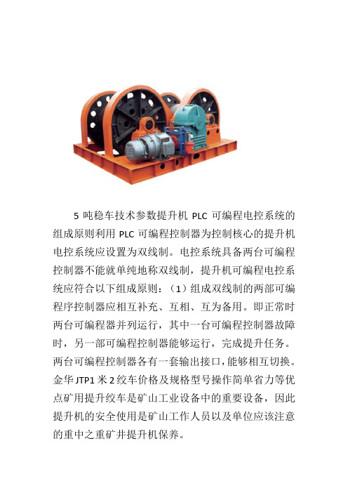
5吨稳车技术参数提升机PLC可编程电控系统的组成原则利用PLC可编程控制器为控制核心的提升机电控系统应设置为双线制。
电控系统具备两台可编程控制器不能就单纯地称双线制,提升机可编程电控系统应符合以下组成原则:(1)组成双线制的两部可编程序控制器应相互补充、互相、互为备用。
即正常时两台可编程器并列运行,其中一台可编程控制器故障时,另一部可编程控制器能够运行,完成提升任务。
两台可编程控制器各有一套输出接口,能够相互切换。
金华JTP1米2绞车价格及规格型号操作简单省力等优点矿用提升绞车是矿山工业设备中的重要设备,因此提升机的安全使用是矿山工作人员以及单位应该注意的重中之重矿井提升机保养。


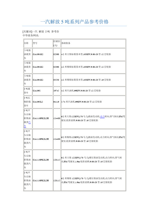
5t叉车的标准荷载摘要:一、引言二、5t叉车的定义与用途三、5t叉车的标准荷载介绍1.最大载重量2.最大起升重量3.最大堆垛重量4.最大牵引重量四、标准荷载对5t叉车性能的影响五、实际操作中应注意的问题六、总结正文:一、引言5t叉车作为一种常见的工业搬运设备,广泛应用于各种物流和仓储场景。
了解其标准荷载对于合理选用和使用叉车具有重要意义。
本文将详细介绍5t叉车的标准荷载相关内容。
二、5t叉车的定义与用途5t叉车,顾名思义,是指最大载重量为5吨的叉车。
它具有较高的承载能力和优秀的搬运性能,适用于各种货物的短途运输、装卸和堆垛作业。
三、5t叉车的标准荷载介绍1.最大载重量最大载重量是指叉车在平坦地面上能安全承载的最大重量。
5t叉车的最大载重量为5吨。
在使用过程中,应确保不超过此荷载限制,以免造成设备损坏和安全隐患。
2.最大起升重量最大起升重量是指叉车在升起货叉时能承受的最大重量。
5t叉车的最大起升重量通常为其载重量的三分之一,即1.67吨。
操作时应注意控制起升高度和速度,避免超负荷运行。
3.最大堆垛重量最大堆垛重量是指叉车在堆垛作业时能承受的最大重量。
5t叉车的最大堆垛重量通常为其最大载重量的一半,即2.5吨。
在堆垛过程中,要确保货物的稳定,避免发生倾倒或滑落事故。
4.最大牵引重量最大牵引重量是指叉车在牵引其他设备或车辆时能承受的最大重量。
5t叉车的最大牵引重量通常为其最大载重量的三分之一,即1.67吨。
牵引其他设备时,应注意控制速度和方向,确保行驶安全。
四、标准荷载对5t叉车性能的影响叉车的性能受荷载影响较大。
超负荷运行会导致设备过早磨损、故障率上升,甚至危及安全。
因此,在使用5t叉车时,应严格按照标准荷载进行操作,确保设备性能和寿命。
五、实际操作中应注意的问题1.在操作5t叉车时,要充分了解货物的重量和尺寸,避免超载。
2.在不同工况下,注意调整叉车的承载重心,保持稳定。
3.遵守安全操作规程,定期进行设备检查和维护。
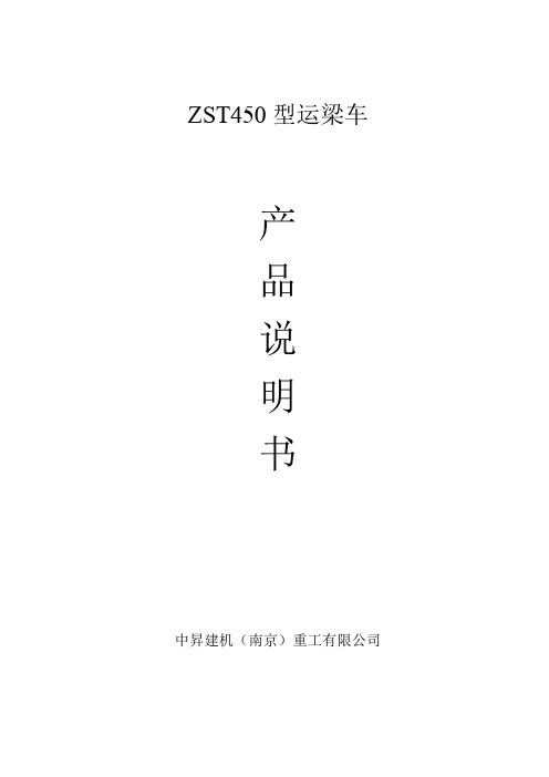
ZST450型运梁车产品说明书中昇建机(南京)重工有限公司目录一、技术性能1. 概述2. 技术规格3. 结构布置二、操作使用1. 运梁车安全操作规程2. 拼装3. 运行前准备4. 空载运行5. 有载运行6. 长途运输中的中途停车检查7. 拆卸8. 运输三、检查、维护、调整注意事项一、技术性能1概述ZST450型运梁车为我公司最新生产的系列大件重载运输设备。
该车主要用于高速铁路专用桥大型混凝土预制箱梁从制梁场运往架桥机后部,配合大型架桥机的施工,同时可整体驮运架桥机,完成架桥机过隧道和转场作业。
ZST450运梁车车架采用快速拼装式高强度钢结构箱形主梁。
车架左右两侧对称布置28个液压悬挂、112个12.00R20轮胎。
28组液压悬挂分大三组可分别调整车架高度,形成整车的第一个三点支承(详见附图1)。
各点中的液压悬挂油缸管路相通,保证轮轴负荷均匀;在坡道上行驶可以调整悬挂高度,使车架尽可能保持水平;车架上装有箱梁支承架A、B。
箱梁支承架A为 2个相互独立,形成2个支点;箱梁支承架B上的2个液压支承油路相通,形成1个支点。
这样就形成了整车的第二个三点支承(详见附图2)。
其位置与混凝土预制箱梁端部的支承点相对固定,纵向间距可根据架梁工况要求调整,从而满足32m和24m不同梁型的混凝土预制箱梁运输要求。
两个三点支承最大限度的保证箱梁在运输转向过程中不受扭。
转向机构采用全液压转向,通过连杆实现全轮转向,使整车转弯半径小,通步性好,并可防止车轮的过度磨损。
ZST450运梁车最大运输能力为450t;接地比压<0.6Mpa;最大克服纵坡3%;整车高度2200±265mm。
该系列运梁车最大运输能力和整车高度可根据用户要求增减。
ZST450型运梁车在设计上有以下几个特点:1.采用进口钢结构设计软件进行优化设计,使得钢结构受力更为合理,在重载运输中车体安全得到进一步保障。
2.电气控制系统采用进口元件PLC(可编程逻辑控制器)进行控制,控制性能可靠,故障少,便于维护。

附件:QDY25/5t电动双梁吊钩式铸造起重机设备采购合同技术协议甲方:信阳东信精密铸造有限公司乙方:河南省新乡市矿山起重机有限公司信阳东信精密铸造有限公司(以下简称甲方),河南省新乡市矿山起重机有限公司(以下简称乙方),就信阳东信精密铸造有限公司起重设备设计、制造事宜中有关设备的供货范围、技术性能要求、设计、加工制造要求以及资料交付等进行了充分讨论,经甲乙双方共同协商就甲方采购25/5t电动双梁吊钩桥式铸造起重机达成以下协议:一、使用概况起重机用于信阳东信精密铸造有限公司铸一车间吊钢水包铁水包使用。
二、主要技术参数1、跨度:S=16.5m2、起升高度:H=12/15m3、起重量:主起升Q=25t4、起重量:副起升Q=5t5、工作级别:主起升A66、大车最大轮压:206KN;铸造起重机7、电动机:主起升:YZR280S-8HC(60%) 38KW副起升:YZR180L-6H 15KW小车运行:YZR160M1- 6H 5.5KW大车运行:YZR180L-8H(60%) 9KW8、减速机:主起升:ZQA750-III-7CA I=40.17副起升:ZQ500-II-3CA I=31.5小车运行:ZSC-400 –I-1 I=22.4大车运行:ZQA400-VI-1/2 I=15.75三、桥架等说明1、驾驶室与刚体滑触线同侧,右侧开门,采用钢化玻璃封闭式司机室,玻璃可更换,装有高度体位可调航空转椅,T4-DR常熟产冷风机,配灭火器及报警器。
2、端梁联结采用高强度螺栓形式。
3、起重机大梁采用正轨箱型梁结构,主要受力构件板材采用Q235-B。
4、大车端梁设检修位置,以便于更换车轮,被动轮侧安装检修吊笼。
5、小车采用悬挂电缆供电,电缆滑轨采用工字钢形式.内挂耐烘烤电缆。
7、操作室布置形式为:控制器由二台联动控制QTB-112/F9305均为左箱大/小车联动台,其中大车带换相触头。
8、制动器采用焦作长江的YWZ9系列制动器,带手动松闸装置,主副钩为双制动,推动器采用优质合金材料。
The following instructions provide valuable information regarding the function and properuse of the Super 5th Wheel Towing System.YOU MUST COMPLETELY READ THE INSTRUCTIONS WITHIN THIS MANUAL, PRIOR TO OPERATING THE HITCH TO PREVENT UNNECESSARY DAMAGE TO THE HITCH, VEHICLE, OR TRAILER.OWNER’S MANUAL#1900 (16K) Industry StandardSuper 5thGross Trailer Weight (Maximum)16,000 lbs.Vertical Load Weight (Max. Pin Weight) 4,000 lbs.#2100 (20K) Industry Standard Super 5th Gross Trailer Weight (Maximum)20,000 lbs.Vertical Load Weight (Max. Pin Weight) 5,000 lbs.#2200 (24K) Industry StandardSuper 5thGross Trailer Weight (Maximum)24,000 lbs.Vertical Load Weight (Max. Pin Weight) 6,000 lbs.A towing system includes each vehicle and component involved in towing. Each item in your towing system has a capacity or weight rating. You trailer has a Gross Vehicle Weight Rating, or GVWR. Your truck has a tow capacity, payload capacity, and possibly more. In addition, your fifth wheel hitch has a weight rating. This weight rating must be at, or above, the GVWR of your trailer for you to tow safely. In addition, if your truck can tow larger loads (has a larger capacity) than the rating of your hitch, your system is only safe to tow loads at the lower rating, that of the hitch.Your mounting kit also has a weight rating, just like your fifth wheel hitch. Many times, these rating are designed to match. But, this is not always the case. Your mounting kit may be higher rated then your fifth wheel hitch, but it also could be lower depending on the components involved. The lowest rating of any one component in the system becomes the rating of the entire system. If your mounting kit is rated to 18,000 lbs., and your hitch is rated at 24,000 lbs., the weight rating of the entire system will not be above 18,000 lbs. Other components in the system could lower the actual system rating further.It is the end users responsibility to ensure a safe towing experience. To this end, it is your responsibility to ensure thatthe truck, trailer, hitching components, and all other items involved are rated or have a capacity sufficient for the loads involved.FIFTH WHEEL PLATE & KING PINThe plate and it’s moving parts should be lubricated with alight lubricant such as WD-40 or 3-in-1 oil, before each trip orPull the Release Handle repeatedly so that the lubricant willspread among the moving parts that may not have otherwisebeen covered sufficiently.coating of WD-40 or other similar lubricant should be used onthe king pin.1901 plate pictured aboveInspect and lubricate the Pivot Bolt monthly with axle grease whenheavily used, or annually with light use. To remove the pivot bolt forlubrication:1.Remove the Fifth Wheel Plate from the Rocker Arm.2.Remove the Hex Nut, Lock Washer and Plastic Washers fromthe Rocker Arm Pivot Bolt.3.Place downward force, compressing the Rocker Arm Spring,enabling the Pivot Bolt to be removed.4.Lube the Pivot Bolt generously with a quality axle grease andreinstall. Tighten the Pivot Bolt to the point where there isresistance when you move the Rocker Arm side-to-side.5. A light coating of lubricant on the hitch pins (below) and pin clipswill help you install and reinstall them easily.Inspect all mounting bracket and hitch hardware, that it is securely fastened. The Fifth Wheel Plate should be removed and inspected, checking all moving parts for wear—clean as directed above. Inspect all mounting bolts for tightness and general condition.When storing your Super 5th hitch, you should be sure that the Fifth Wheel Plate parts are lubricated with WD-40 to retard the formation of rust. Cover the entire assembly to prevent accumulation of dirt, grime, or rust.ANNUAL MAINTENANCE•The Super 5th hitch is equipped with a side-to-side pivot feature. There should be a minimum of 6” between the truckbed rails and the under side of the trailer for side tilt clearance. It is the customers responsibility to adjust the trailer king pin box for the appropriate amount of clearance depending on the terrain being traveled (example: some State Parks are sloped and unpaved; some driveways are steeply angled). If after-market bed covers are added, care must be taken to allow for additional clearance.CAUTION rocker arm pivot bolt rocker arm rocker arm springhitch pinspin cliplock bar springpin cliprelease handlepush nut lock catch springlock kit1901 PLATE1.Remove the Fifth Wheel Plate from the Rocker Arm and place it upside down on a smooth, clean surface.2.Insert the Release Handle into the obround hole of the plate as seen above.3.The Lock Bar Spring must be placed inside the handle prior to placing the handle down over the pin of the Lock BarAssembly, “catching” the hook inside the handle around the pin.4.Push the handle and spring assembly down past the groove in the pin of the Lock Bar Assembly, and place one of thePin Clips in the groove of the pin to fasten.5.Grip the body of the spring and stretch it far enough over the opposite pin (welded to the plate) and push it down pastthe groove.6.Install the Push Nut to secure the Lock Bar Spring onto the welded pin.NOTE : The 1901 plate for the #1900 Super 5th does not use a pushnut to attach the end of the spring, but rather a slot in the sideof the fifth wheel plate located above the obround hole. Seeillustration to the right.As a PullRite fifth wheel hitch owner, it is important for you to study andmanually operate the Fifth Wheel Plate and Release Handle to betterunderstand the locking action. A better working knowledge of the plate willhelp prevent accidental dropping of your trailer due to incorrect hitching.Also, it is imperative that you study and adhere to the Maintenance procedures provided in the Owners Manual. If you did not receive one upon purchase, please contact PullRite or visit us on the web at .A better understanding of the plates locking and un-locking operation can be obtained by viewing the working parts from the underside of the plate. The Fifth Wheel Plate can be removed and turned over to view the workings of the mechanism. When operating the Fifth Wheel Plate manually, please be aware that the Lock Jaw Assembly has more movement capability when there is not a king pin present to center the assembly. Refer to the illustrations below for part identification (#3601 plate pictured below; #1900 Super 5th uses plate #1901, but both function similarly).1.To open the locking mechanism, lift and pull the Release Handle out until the Lock Catch engages the Lock JawAssembly (see illustrations on the opposite page).2.As the trailer king pin moves into the plate, it will contact the Lock Lever, forcing the Lock Catch to disengage the LockJaw Assembly, allowing the Lock Bar Spring to close the Lock Jaw Assembly behind the King Pin. The King Pin must be fully engaged in the plate slot or the Lock Jaw Assembly will not seat properly, and the Handle Catch would not then engage the inner side wall of the plate. To be certain that the Lock Jaw Assembly has closed fully, attempt to pull the Release Handle without first lifting it.NOTE:Please note that when lifting the handle to clear the side wall of the plate with the handle catch, it will benecessary to pull with some force to begin the Lock Jaw rotation. Merely lifting the Release Handle willnot cause the Handle to “pop” open and rotate the Lock Jaw to the open position.3.To discourage theft or pranksters, place a padlock through the obround hole above the Release Handle (see Illustration below).OPEN -- UNLOCKED POSITION Lock Jaw AssemblyHandle CatchCLOSED -- LOCKED POSITIONLock CatchLock BarLock Bar Spring Lock LeverOPENCLOSEDLIFT UPWARDAND PULLOUT WITHFORCE UNTILLOCK CATCH ENGAGESCAUTION: DO NOT ATTEMPT TO TRIP THE LOCK MECHANISM WITH YOUR HAND. USE A PROBE DEVICETO SIMULATE THE KING PIN ACTIONThe #1900, #2100, and #2200 Industry Standard Super 5th’s are height adjustable models. To adjust the crossmember to one of four available positions, refer to the illustration below:1.Remove Head Assembly. To remove Head Assembly remove Clevis Pins and Clips.2.Remove the 1/2” bolts (#1900 or #2100 models) or 5/8” bolts (#2200 model) that attaches the Crossmember to theSide Body Bracket.3.Position Crossmember to the correct height and reinstall bolts, washers, and nuts.4.Torque 1/2” bolts to 75 ft. lbs. or 5/8” bolts to 151 ft. lbs.5.Reinstall Head Assembly, Clevis Pins, and Clips.1/2” - 13 boltsHead AssemblyWARNING: Never perform any of the following actions while any part of a person is between the vehicle and trailer.1.Align your truck with the center of the trailer. The truck should be close to parallel to the centerline of the trailer.2.Block the trailer wheels so the trailer will not roll back.3.Lower your tailgate and back up until there is about 6” of clearance between the Super 5th and the end of the fifthwheel plate. Raise or lower the front of the trailer so the bottom of the plate is aligned slightly above the beginning of the ramp area of the Fifth Wheel Plate. This procedure will cause the front edge of the trailer plate to “ride up” the ramp and flatten or tilt the hitch plate into a parallel position.CAUTION: If this procedure is not followed, the kingpin may bind in the plate mechanismand not lock-in properly. Following theprocedure as outlined in Step 3 willensure that you will not “high hook” theking pin in the plate. “High hooking”occurs when backing your hitch intoa trailer that is set too high, resultingin the lower flange of the king pin towedge itself against the metal edge ofthe lower horseshoe piece or againstthe Lock Jaw Assembly. Damage to theLock Jaw Assembly may result and notallow smooth operation of the closingmechanism.4.The Fifth Wheel Latch must be in the openposition (see illustration on pgs. 6 & 7). Lift andpull out on the Release Handle to open the LockJaw Assembly.CAUTION: Damage will result should you attempt to hook up with the Lock Jaw Assembly inthe closed position.5.Back up the truck in one fluid motion, so the kingpin enters the center of the Fifth Wheel Plateopening.6.Make sure the Lock Jaw Assembly is completelyseated around the king pin.7.Be sure that the Release Handle has fullyreturned to the closed position and proceed to“Safety Checks” on pg. 10.Ramp1.Shine a light on the Fifth Wheel Plate Lock Jaw Assembly making sure it has closed around the king pin.2.Pull the Release Handle towards you without lifting it up. If the Lock Jaw Assembly is completely closed the HandleCatch will prevent you from being able to pull the Release Handle open.3.Raise the trailer jack base plates just above the ground, lock your trailer brakes, then pull the tow vehicle slowlyforward putting a strain on the trailer.4.When you are assured that the trailer is safely hooked up, raise your trailer jacks into their full retracted position.FAILURE TO PERFORM THESE SAFETY CHECKS MAY RESULT IN DAMAGES TO TRUCK AND TRAILER.WARNING: Never perform any of the following actions while any part of a person is between the vehicle and the trailer.1.Once you have the trailer located and are ready to unhitch, block the trailer wheels so it will not roll back or forward.Back into the blocked trailer slightly and set the parking brake while you are still in gear. This action will relieve pressure on the lock mechanism before attempting to release the latch mechanism.2.Lower the trailer jacks to the point of just touching the ground but do not raise the trailer at this point.3.Open the Lock Jaw Assembly by first lifting, then pulling the Release Handle towards you (see pgs. 6 & 7).4.Lower the trailer jacks until the bottom of the king pin box is almost free of the top of the Fifth Wheel Plate. Makecertain that the bottom of the king pin is not so high that binding on the hitch Lock Catch would result.5.After lowering the truck’s tail gate, disconnect the trailer electrical cord and break-away switch cable, then pullforward.6.As the king pin slides from the Fifth Wheel Plate, notice that the locking mechanism remains open once the king pin isremoved.CAUTION: If it should be necessary to reposition your trailer, you must follow the hitching procedures to ensure the hitch is latched before moving the trailer.CAUTION: You may wish to keep the plate closed until you are ready to re-hitch to avoid injury or accidents to children or adults who attempt to operate the plate mechanism. DO NOT ATTEMPT TO TRIP THE LOCKMECHANISM WITH YOUR HAND, USE A PROBE TO SIMULATE THE KING PIN.ILLUSTRATION — #2200 EXPLODED VIEWAB2B5B6BCD1D2B7D5B1B3B10B8B9B4D3D4DILLUSTRATION — #2100 EXPLODED VIEWAB2B5B6BCD1D2B7D5B1B3B10B8B9B4D3D4DILLUSTRATION — #1900 EXPLODED VIEWAB2B5B6BCD1D2B7D5B1B3B10B8B9B4D3D4DPULLIAM ENTERPRISES, INC. hereinafter referred to as “PULLIAM”, warrants to the rst retail owner only, this PullRite towing system to be free from defects in materials and workmanship for a period of ve (5) years or 31,068 miles (50,000 km) after the installation on purchaser’s vehicle, whichever occurs rst.To validate this warranty, the r st retail owner must mail the provided warranty card to PULLIAM, within ten (10) days after installation of said towing system on his vehicle.The owner is responsible for all normal and preventative maintenance described in the Owner’s Manual.If any defect occurs which the owner believes is covered by this warranty within said ve (5) year period, the owner shall contact PULLIAM immediately, either in writing or by telephone call, Attention Customer Service Department. The owner will be instructed to return the hitch at his expense either to an authorized PullRite dealer or to PULLIAM to repair or replace any parts necessary to correct defects in material or workmanship.Repair or replacement shall be at the sole option of PULLIAM and shall be completed by or on behalf of PULLIAM free of charge for materials and labor.This warranty gives you speci c legal rights, and you may also have other right’s which vary from state to state.THIS WARRANTY SPECIFICALLY EXCLUDES EACH OF THE FOLLOWING:1.Defects in the product resulting from misuse, neglect, accident, loading beyond the vehicle’scapacity, failure to comply with instructions contained in the Owner’s Manual or unauthorizedrepairs, replacements, alterations or modi cations. “Unauthorized repair, replacements,alterations” are those made without PULLIAM’S prior knowledge and consent.2.Any incidental or consequential damage including, but not limited to, loss of use of the vehicle,towing charges, vehicle rental, loss of time, inconvenience, travel, gasoline, lodging and telephoneexpenses, loss of revenue and damages on account of personal injury and property damage.(Some states do not allow the exclusion or limitation of incidental or consequential damages, sothese limitations may not apply to you).3.Repairs or replacements of defects in any PullRite towing system, or part thereof, installed on anyvehicle which has been rented, leased or used for any commercial purpose.4.Any representation, warranty of undertaking made by any dealer or third party beyond the scopeof the warranty herein expressed.5.Any problem resulting in normal deterioration due to wear or exposure.TO THE EXTENT PERMITTED BY LAW, IMPLIED WARRANTIES OF MERCHANTABILITY AND FITNESS FOR A PARTICULAR PURPOSE ARE LIMITED IN DURATION TO FIVE YEARS FROM THE DATE OF INST ALLATION ON THE FIRST OWNER’S VEHICLE. (SOME ST ATES, HOWEVER, DO NOT ALLOW LIMITATIONS AS TO DURATION OF IMPLIED WARRANTY, SO THOSE LIMITATIONS MAY NOT APPLY TO YOU)Product Warranty RegistrationName:________________________________________________________________________________Address:________________________________________________________________________________City:____________________________State:______________Zip:_________________Email Address:____________________________________________________________Phone (opti onal):____________________________Purchase Price:____________________________Date of Purchase:__________________________________As an owner of a PullRite product, you must register your product to be considered forwarranty coverage. See Owners Manual for further details.Dealer’s Name:____________________________________________Dealer’s Address:____________________________________________Dealer’s City:____________________________Dealer’s State:______________Dealer’s Zip:_________________Dealer’s Phone:____________________________Model Purchased:____________________________________________Vehicle Make:____________________________Vehicle Model:______________Vehicle Year:_________________Vehicle Year:____________________________Vehicle Cab Style:______________Vehicle Bed Length:_________________Did you receive an Owners Manual from the Dealer? Yes / NoWhat infl uenced you to buy your hitch?_____________________________________________________________________Comments:。
高品质手动搬运车、电动叉车价格优惠尽在邦势启
POSUP 邦势启 5 吨重载型手动搬运车 ●重型设计可搬运重载货物。
●独特的液压泵确保省力轻松地提升重载货物。
●重载负荷而轻松搬运! ●载轮:d=Ø80×68 毫米, 双轮钢制 ●驱动轮:D=Ø200×50 毫米, 钢制 注:在选购电动叉车、电动搬运车、手动搬运车、电动观光车及了解叉车价格之前,一定要 登录邦势启官网或咨询免费电话 400-7283-599 咨询客服每个型号的不同用途及特点,这样 才能准确选择自己需要的产品,避免带来不必要的麻烦。
货号 额定载重 货叉最高高度 货叉最低高度 货叉长度 货叉外宽宽度 单货叉宽 前轮尺寸及材质 后轮尺寸及材质 净重
单位 kg mm mm mm mm mm mm mm kg
PD010009 5000 200 90 1150 580 210 Φ80×70 Φ200×50 192
PD010010 5000 200 90 1150 680 210
200
高品质手动搬运车、电动叉车价格优惠尽在邦势启
手动搬运车产品来源:邦势启工业设备(上海)有限公司官网: 扫一扫关注邦势启微信,有惊喜等你来哦
。