辐射和天线antenna
- 格式:ppt
- 大小:253.00 KB
- 文档页数:29
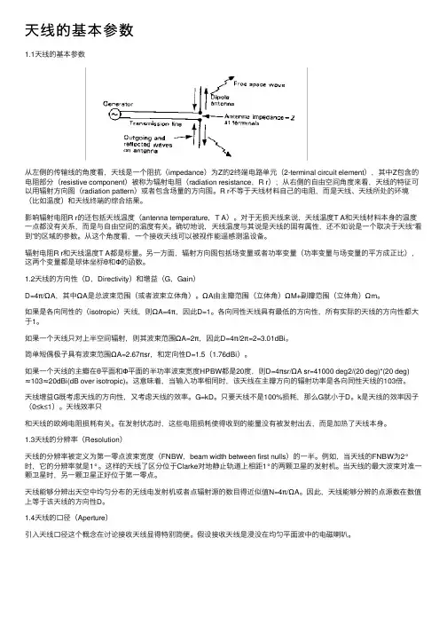
天线的基本参数1.1天线的基本参数从左侧的传输线的⾓度看,天线是⼀个阻抗(impedance)为Z的2终端电路单元(2-terminal circuit element),其中Z包含的电阻部分(resistive component)被称为辐射电阻(radiation resistance,R r);从右侧的⾃由空间⾓度来看,天线的特征可以⽤辐射⽅向图(radiation pattern)或者包含场量的⽅向图。
R r不等于天线材料⾃⼰的电阻,⽽是天线、天线所处的环境(⽐如温度)和天线终端的综合结果。
影响辐射电阻R r的还包括天线温度(antenna temperature,T A)。
对于⽆损天线来说,天线温度T A和天线材料本⾝的温度⼀点都没有关系,⽽是与⾃由空间的温度有关。
确切地说,天线温度与其说是天线的固有属性,还不如说是⼀个取决于天线“看到”的区域的参数。
从这个⾓度看,⼀个接收天线可以被视作能遥感测温设备。
辐射电阻R r和天线温度T A都是标量。
另⼀⽅⾯,辐射⽅向图包括场变量或者功率变量(功率变量与场变量的平⽅成正⽐),这两个变量都是球体坐标θ和Φ的函数。
1.2天线的⽅向性(D,Directivity)和增益(G,Gain)D=4π/ΩA,其中ΩA是总波束范围(或者波束⽴体⾓)。
ΩA由主瓣范围(⽴体⾓)ΩM+副瓣范围(⽴体⾓)Ωm。
如果是各向同性的(isotropic)天线,则ΩA=4π,因此D=1。
各向同性天线具有最低的⽅向性,所有实际的天线的⽅向性都⼤于1。
如果⼀个天线只对上半空间辐射,则其波束范围ΩA=2π,因此D=4π/2π=2=3.01dBi。
简单短偶极⼦具有波束范围ΩA=2.67πsr,和定向性D=1.5(1.76dBi)。
如果⼀个天线的主瓣在θ平⾯和Φ平⾯的半功率波束宽度HPBW都是20度,则D=4πsr/ΩA sr=41000 deg2/(20 deg)*(20 deg)≈103≈20dBi(dB over isotropic)。
八木天线的原理和制作概要八木天线(Yagi-Uda Antenna)是一种常用的定向性天线,广泛应用于无线通信、电视、无线电等领域。
八木天线以其简单的结构和高增益而受到青睐。
其工作原理是基于干涉和辐射。
八木天线的结构包括一个驱动元件(又称为激励器)和若干个反射元件和辐射元件组成。
驱动元件一般为一个有源的振荡天线,如偶极子,通过振荡产生的电磁波激发其他元件。
反射元件位于驱动元件的后方,起到集中反射电磁波的作用。
辐射元件则位于驱动元件的前方,起到扩散辐射电磁波的作用。
通过这样的结构,八木天线能够提高天线的增益,增强信号的传输方向性。
八木天线的反射元件由若干个均匀定位的平行的金属棒组成,其长度与驱动元件的工作频率有关。
反射元件比驱动元件短约1/4波长,从而实现相位差。
当反射元件上的电流被激发时,它们会发出电磁波,将电磁波聚焦到驱动元件的边缘,因此可以抑制边缘辐射。
这种电磁波的相干性与反射元件的长度、数量等因素有关。
辐射元件由若干个均匀定位的平行金属棒组成,其长度比驱动元件短约1/2波长。
辐射元件的长度和距离驱动元件的距离也会影响天线的增益和方向性。
当激励器产生的电磁波通过驱动元件传入辐射元件时,电磁波在辐射元件上会产生类似干涉的效应,增加电磁波辐射的方向性,以及进一步增强电磁波的辐射功率。
制作八木天线的步骤如下:1.根据要接收或发射的信号频率计算波长,根据波长确定驱动元件、反射元件和辐射元件的长度。
2.准备天线材料,一般为厚度适中、导电性能良好的金属棒,如铝棒。
3.构建驱动元件,可选择一根合适长度的金属棒作为驱动元件,在其一端连接激励器。
4.构建反射元件,根据计算得到的长度要求,制作若干个金属棒,间隔适当,一端与驱动元件连接。
5.构建辐射元件,根据计算得到的长度要求,制作若干个金属棒,与驱动元件的另一端连接。
6.连接和固定天线元件,确保元件之间的相对位置和长度精确。
使用导线连接驱动元件和激励器。
7.进行天线的测试和调整,根据实际效果来优化天线的性能。
天线知识图解(Antenna)3月17日天线是一个相当庞大的话题,很难用一篇文章来描述天线的每个方面,但我会尝试给出一些天线的各个方面的大图片,主要用于蜂窝应用。
天线是什么?如何表现天线的性能?辐射模型天线增益总辐射功率TRPTotal Isotropic Sensitivity (TIS)Effective Isotropic Radiated Power/Equivalent Isotropic Radiated Power (EIRP)S11什么是天线?众所周知,天线是一种将电能(电信号)转换成电磁波并传送到太空的装置。
外面有各种类型的天线,下面是一些例子。
这些只是一些例子,还有很多其他类型。
看看有多少你熟悉的。
现在在大多数移动通信设备中,天线都被嵌入到一个很小的空间里。
在一个相对久远的移动电话,你可能已经看到了天线显示在左侧的图片(鞭天线)。
在大多数的移动设备,你看到这些天,天线是嵌入的情况下,或正确的印刷电路板如下所示。
随着移动设备(例如智能手机)在一个设备中获得越来越多的技术(例如,带有各种频段/ 无线接入技术的蜂窝技术,蓝牙,无线网络等) ,设计多个天线并将其放入一个小空间变得越来越困难。
如何表现天线的性能?有两个主要的标准来评估天线的性能,如下(a)应该把电能转换成电磁能,尽可能减少损失;(b)希望辐射在我需要的方向上。
有几个指标可以代表天线的性能如下辐射模型;总辐射功率;总的各向同性灵敏度。
辐射模型了解/ 评估天线性能的第一步是检查天线的辐射模型。
在大多数情况下,电能都是通过预先设定好的路径流动的,这种路径通常建立在铜线或印刷电路板上的铜痕迹上,但是一旦电能转化为电磁波,它几乎就会向四面八方传播。
根据我们设计天线的思路,电磁波在空气中传播的方向是不同的。
天线在某些方向上传输很强的能量,在某些方向上传输少量的能量,在某些方向上传输中等范围的能量等,这种能量传输方式被称为“辐射方向图”。
螺旋天线的结构和辐射原理英文回答:A helical antenna is a type of radio antenna that consists of a conducting wire wound in the shape of a helix. The helix is usually mounted on a cylindrical or conical support structure. The pitch of the helix (the distance between adjacent turns) and the diameter of the wire determine the antenna's resonant frequency.Helical antennas are widely used in a variety of applications, including:Satellite communications.Mobile communications.Radar.Navigation.Medical imaging.The radiation pattern of a helical antenna is determined by the number of turns in the helix, the pitch of the helix, and the diameter of the wire. A helical antenna with a large number of turns will have a narrow beamwidth, while a helical antenna with a small number of turns will have a wide beamwidth. The pitch of the helix affects the antenna's gain and bandwidth. A helical antenna with a small pitch will have a high gain and a narrow bandwidth, while a helical antenna with a large pitch will have a low gain and a wide bandwidth. The diameter of the wire affects the antenna's input impedance. A helical antenna with a large diameter wire will have a low input impedance, while a helical antenna with a small diameter wire will have a high input impedance.中文回答:螺旋天线的结构与辐射原理。

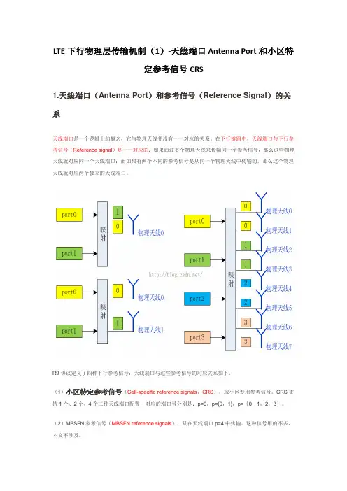
LTE下行物理层传输机制(1)-天线端口Antenna Port和小区特定参考信号CRS1.天线端口(Antenna Port)和参考信号(Reference Signal)的关系天线端口是一个逻辑上的概念,它与物理天线并没有一一对应的关系。
在下行链路中,天线端口与下行参考信号(Reference signal)是一一对应的:如果通过多个物理天线来传输同一个参考信号,那么这些物理天线就对应同一个天线端口;而如果有两个不同的参考信号是从同一个物理天线中传输的,那么这个物理天线就对应两个独立的天线端口。
R9协议定义了四种下行参考信号,天线端口与这些参考信号的对应关系如下:(1)小区特定参考信号(Cell-specific reference signals,CRS),或小区专用参考信号。
CRS支持1个、2个、4个三种天线端口配置,对应的端口号分别是:p=0,p={0,1},p={0,1,2,3}。
(2)MBSFN参考信号(MBSFN reference signals),只在天线端口p=4中传输。
这种信号用的不多,本文不涉及。
(3)UE特定参考信号(UE-specific reference signals),或UE专用参考信号,有的英文资料中也把这种信号称作解调参考信号(Demodulation reference signals,DM-RS)。
可以在天线端口p=5,p=7,p=8,或p={7,8}中传输。
这块内容在后面的博文中再写。
(4)定位参考信号(Positioning reference signals),只在天线端口p=6中传输。
这种信号用的不多,本文不涉及。
2.小区特定参考信号的结构示意图设计小区特定参考信号(Cell-specific reference signals)的目的并不是为了承载用户数据,而是在于提供一种技术手段,可以让终端进行下行信道的估计。
终端可以通过对小区特定参考信号的测量,得到下行CQI、PMI、RI等信息。
天线系数af(antenna factor)表达式的推导过程概述说明1. 引言1.1 概述在无线通信和电磁测量领域,天线是起到收发信号和辐射电磁波的重要设备。
天线的性能评估需要考虑许多因素,其中之一是天线系数(Antenna Factor,简称AF)。
天线系数是描述天线接收或辐射功率与外场电场强度之间关系的一个重要参数。
本文旨在推导天线系数AF 的表达式,通过该表达式可以更准确地计算天线的接收或辐射功率。
1.2 文章结构本文将按如下结构进行叙述:引言部分概述了文章的背景和目的;正文部分详细介绍了相关概念和理论知识;推导过程部分将逐步推导出天线系数AF 的表达式;结论部分对推导过程进行总结,并通过实例验证了AF 表达式的准确性与可靠性。
1.3 目的本文旨在提供一个清晰明了的方法,用以推导出准确计算天线系数AF 的表达式。
通过这个表达式可以更好地评估、设计和优化各种类型的天线系统。
随着近年来无线通信技术和电磁测量技术的迅速发展,对天线性能的要求也越来越高。
推导出准确的AF 表达式,可以帮助工程师更好地了解天线的性能及其在特定外场环境下的表现,从而指导天线系统的优化和改进。
在接下来的正文部分,将详细介绍与天线系数相关的概念和理论知识,并逐步推导出AF 的表达式。
2. 正文在我们探讨天线系数af(antenna factor)表达式的推导过程之前,首先需要了解什么是天线系数以及它的意义。
天线系数af是指天线辐射场强与入射场强之比,它实际上是一个用于描述天线性能的重要参数。
正如我们在前面提到的,天线系数af可以表示为:af = E / Ei其中,E代表天线接收到的辐射场强度,Ei则表示入射到天线上的总场强度。
通过衡量这两个值之间的比例关系,我们可以得到有关天线性能优劣和信号接收质量的信息。
现在让我们来详细介绍如何推导出天线系数af的表达式。
首先需要明确一点,在进行推导之前,我们需要知道所使用的具体天线类型以及其特性参数。

方向性系数、增益;极化;输入阻抗、辐射阻抗和
天线(Antenna)是用来传输无线信号的一种集成电路,它具有转换和传输的功能。
它能把一种能量,如电磁波转换成另一种。
为了保证信号的传输效率,天线应具有良好的
方向性、增益和极化等特性。
方向性指的是天线在接收和发射信号时,探测方向的变量。
它决定了天线在什么方向
上能够把最大能量传输出去,越高的方向性性能意味着幅度和功率大,而由下而上的传输
功率又说明着能量被局部传输,因此,天线的高方向性特性使得在传送带宽较大的信号应
用中更为关键。
增益的大小决定了天线的功率放大效率,它是指发射功率与收到信号电平之间的关系。
通常情况下,较好的效根,能够更好地放大信号,而信号放大后系统操作性能也会有改善。
极化指的是天线收发双向的能量分布模式,它决定了天线接收信号或发射信号的特性,采用不同极化方式可以获得不同的性能。
输入阻抗决定了整个系统的运作参数,它表示放大器和信号源或收发机之间的电阻。
此阻抗的值影响整个系统的工作效果。
辐射阻抗和驻波比被用来衡量一个系统的效率,它是指一个系统在信号发射和散射时
时间和功率所涉及的量度。
发射功率要比接收功率高,系统的驻波比值应该偏高,表示该
系统可以有效地传输信号的能量。

什么叫天线?什么叫增益?什么叫地网?(有示意图)天线是一种能量转换器,它的作用是将发信机输出的高频震荡信号转换为电磁波向空中辐射,另一方面,把从空中接受到的电磁波转变成高频震荡信号传输给收信机。
天线的家族非常庞大,有很多天线是我们在生活中根本遇不到的,所以不用深究。
但是作为业余无线电爱好者,我们还是应该了解一下我们身边常用的天线,在这篇文章中我们主要谈谈 GP 天线。
GP 天线的英文全称是:Ground Plane Antenna,即“带接地面的天线”,也可以称为“地平面天线”或简称为“接地天线”。
GP 天线是我们在 U/V 段通讯时最常使用的天线类型,其家族成员包括了车载鞭状天线、玻璃钢基地天线、手持设备上的小型天线等。
由于在 U/V 段通讯中多采用垂直极化方式,这些天线通常采用垂直方式进行架设,所以,这些天线又叫做“垂直接地天线”。
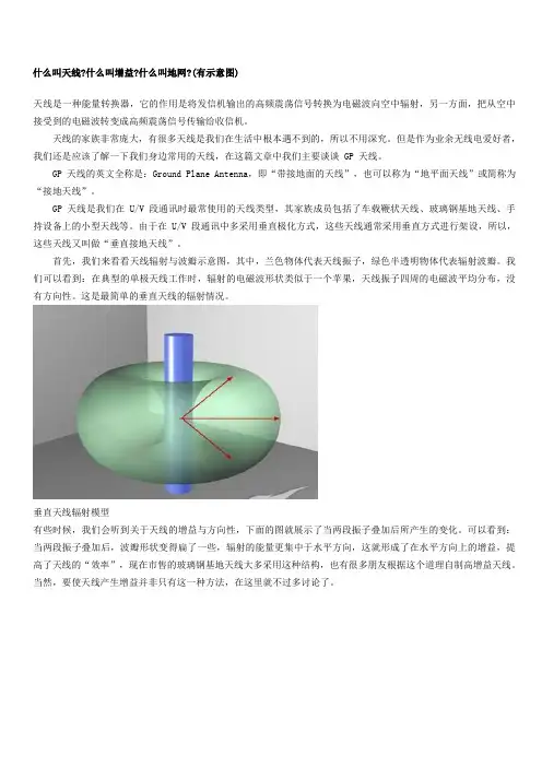
首先,我们来看看天线辐射与波瓣示意图,其中,兰色物体代表天线振子,绿色半透明物体代表辐射波瓣。
我们可以看到:在典型的单极天线工作时,辐射的电磁波形状类似于一个苹果,天线振子四周的电磁波平均分布,没有方向性。
这是最简单的垂直天线的辐射情况。
垂直天线辐射模型有些时候,我们会听到关于天线的增益与方向性,下面的图就展示了当两段振子叠加后所产生的变化。
可以看到:当两段振子叠加后,波瓣形状变得扁了一些,辐射的能量更集中于水平方向,这就形成了在水平方向上的增益,提高了天线的“效率”,现在市售的玻璃钢基地天线大多采用这种结构,也有很多朋友根据这个道理自制高增益天线。
当然,要使天线产生增益并非只有这一种方法,在这里就不过多讨论了。
天线增益了解了天线的辐射,我们再来看看 GP 天线的情况。
GP 天线一般由同轴电缆馈电,内导体接振子,外导体接于“接地面”。
“接地面”就是我们常说的“地网”。
下图是典型的 GP 天线在接地面为无穷大时的辐射情况,电波基本沿水平方向辐射,这是理想的状态。
理想辐射状态然而,在制造天线时,我们不可能把接地面做到无穷大,必须缩小到我们可以承受的范围,但是那样又造成了辐射方向的改变。
天线的英文单词天线(Antenna)是指用于接收和发送无线电信号的装置,它是无线电通信系统的重要组成部分。
无线电通信是现代通信方式之一,它广泛应用于移动通信、广播电视、卫星通信、雷达、导航等领域。
因此,天线的重要性不言而喻。
天线的种类有很多,常见的有线性天线、天线阵列、圆极化天线、扇形天线等。
其中,线性天线是最基本的一种天线,它是由一段长度为λ/4的导体组成的,λ代表无线电波的波长。
它适用于接收和发送水平偏振的无线电信号,如电视信号、中短波广播等。
天线阵列是由多个线性天线组成的,可以实现相控阵和波束形成,提高信噪比和抗干扰能力。
圆极化天线是一种特殊的线性天线,它可以实现圆偏振信号的接收和发送,适用于卫星通信、移动通信等领域。
扇形天线则是一种具有方向性的天线,可以实现地面覆盖和局域覆盖等通信方式。
天线的主要参数有增益、带宽、方向性、驻波比等。
增益是指天线辐射功率与同等条件下参考天线辐射功率的比值,是衡量天线性能的重要指标。
带宽是指天线能够接收和发送的频率范围,一般用-3dB 带宽表示。
方向性是指天线在空间中辐射和接收信号的能力,也称为天线的指向性。
驻波比是指天线输出电压和输入电压的幅度比,它反映了天线与传输线之间的匹配程度。
天线的应用非常广泛,无线电通信领域几乎无处不在。
在移动通信中,手机天线是必不可少的,它可以实现手机与基站之间的通信,使人们可以随时随地进行通信。
在广播电视领域,天线是接收电视信号的必备设备,它可以将电视信号转化为电视画面和声音。
在卫星通信领域,天线是卫星与地面站之间的通信设备,它可以实现全球通信和导航。
在雷达和导航领域,天线是探测和发送信号的重要组成部分,可以实现目标探测和导航定位。
总之,天线是无线电通信的关键技术之一,它的性能直接影响到通信质量和可靠性。
随着无线通信技术的不断发展,天线的种类和应用也在不断增加和拓展。
因此,对天线的研究和应用具有重要的意义。
IEEE 和天线有关名词的定义Antenna: "That part of a transmitting or receiving system which is designed to radiate or to receive electromagnetic waves". An antenna can also be viewed as a transitional structure (transducer) between free-space and a transmission line (such as a coaxial line). An important property of an antenna is the ability to focus and shape the radiated power in space e.g.: it enhances the power in some wanted directions and suppresses the power in other directions.Frequency bandwidth:"The range of frequencies within which the performance of the antenna, with respect to some characteristics, conforms to a specified standard". VSWR of an antenna is the main bandwidth limiting factor.Input impedance: " The impedance presented by an antenna at its terminals". The input impedance is a complex function of frequency with real and imaginary parts. The input impedance is graphically displayed using a Smith chart. Reflection coefficient: The ratio of the voltages corresponding to the reflected and incident waves at the antenna's input terminal (normalized to some impedance Z0). The return loss is related to the input impedance Zin and the characteristic impedance Z0 of the connecting feed line by: Gin = (Zin - Z0) / (Zin+Z0).Voltage standing wave ratio (VSWR): The ratio of the maximum/minimum values of standing wave pattern along a transmission line to which a load is connected. VSWR value ranges from 1 (matched load) to infinity for a short or an open load. For most base station antennas the maximum acceptable value of VSWR is 1.5. VSWR is related to the reflection coefficient Gin by: VSWR= (1+|Gin|)/(1-| Gin |).Isolation: "A measure of power transfer from one antenna to another". This is also the ratio of the power input to one antenna to the power received by the other antenna, expressed in decibel (dB). The same definition is applicable to two-port antennas such as dual-polarization antennas.Far-field region: "That region of the field of an antenna where the angular field distribution is essentially independent of the distance from a specified point in the antenna region". The radiation pattern is measured in the far field. Antenna polarization: "In a specified direction from an antenna and at a point in its far field, is the polarization of the (locally) plane wave which is used to represent the radiated wave at that point". "At any point in the far-field of an antenna the radiated wave can be represented by a plane wave whose electric field strength is the same as that of the wave and whose direction ofpropagation is in the radial direction from the antenna. As the radial distance approaches infinity, the radius of curvature of the radiated wave's phase front also approaches infinity and thus in any specified direction the wave appears locally a plane wave". In practice, polarization of the radiated energy varies with the direction from the center of the antenna so that different parts of the pattern and different side lobes sometimes have different polarization. The polarization of a radiated wave can be linear or elliptical (with circular being a special case).Co-polarization: "That polarization which the antenna is intended to radiate".Cross-polarization: "In a specified plane containing the reference polarization ellipse, the polarization orthogonal to a specified reference polarization". The reference polarization is usually the co-polarization.Antenna pattern: The antenna pattern is a graphical representation in three dimensions of the radiation of the antenna as a function of angular direction. Antenna radiation performance is usually measured and recorded in two orthogonal principal planes (such as E-Plane and H-plane or vertical and horizontal planes). The pattern is usually plotted either in polar or rectangular coordinates. The pattern of most base station antennas contains a main lobe and several minor lobes, termed side lobes. A side lobe occurring in space in the direction opposite to the main lobe is called back lobe.Normalized pattern: Normalizing the power/field with respect to its maximum value yields a normalized power/field pattern with a maximum value of unity (or 0 dB).Gain pattern: Normalizing the power/field to that of a reference antenna yields a gain pattern. When the reference is an isotropic antenna, the gain is expressed in dBi. When the reference is a half-wave dipole in free space, the gain is expressed in dBd.Radiation efficiency: "The ratio of the total power radiated by an antenna to the net power accepted by the antenna from the connected transmitter".E-plane:"For a linearly polarized antenna, the plane containing the electric field vector and the direction of maximum radiation". For base station antenna, the E-plane usually coincides with the vertical plane.H-plane: "For a linearly polarized antenna, the plane containing the magnetic field vector and the direction of maximum radiation". For base station antenna, the H-plane usually coincides with the horizontal plane.Front-to-back ratio: "The ratio of the maximum directivity of an antenna to itsdirectivity in a specified rearward direction". Sometimes the directivity in the rearward direction is taken as the average over an angular region.Major/main lobe: "The radiation lobe containing the direction of maximum radiation". For most practical antenna there is only one main beam.Side lobe level: Is the ratio, in decibels (dB), of the amplitude at the peak of the main lobe to the amplitude at the peak of a side lobe.Half-power beamwidth: " In a radiation pattern cut containing the direction of the maximum of a lobe, the angle between the two directions in which the radiation intensity is one-half the maximum value". The Half-power beamwidth is also commonly referred to as the 3-dB beamwidth.Antenna directivity: The directivity of an antenna is given by the ratio of the maximum radiation intensity (power per unit solid angle) to the average radiation intensity (averaged over a sphere). The directivity of any source, other than isotropic, is always greater than unity.Antenna gain:The maximum gain of an antenna is simply defined as the product of the directivity by efficiency. If the efficiency is not 100 percent, the gain is less than the directivity. When the reference is a loss less isotropic antenna, the gain is expressed in dBi. When the reference is a half wave dipole antenna, the gain is expressed in dBd (1 dBd = 2.15 dBi ).Antenna efficiency: The total antenna efficiency accounts for the following losses: (1) reflection because of mismatch between the feeding transmission line and the antenna and (2) the conductor and dielectric losses.Effective radiated power (ERP): "In a given direction, the relative gain of a transmitting antenna with respect to the maximum directivity of a half-wave dipole multiplied by the net power accepted by the antenna from the connected transmitter".Power handling: Is the ability of an antenna to handle high power without failure. High power in antenna can cause voltage breakdown and excessive heat (due to conductor and dielectric antenna losses) which would results in an antenna failure.Passive intermodulation (PIM):As in active devices, passive intermodulation occurs when signals at two or more frequencies mix with each other in a non-linear manner to produce spurious signals. PIM is caused by a multitude of factors present in the RF signal path. These include poor mechanical contact, presence of ferrous contents in connectors and metals, andcontact between two galvanically unmatched metals. PIM spurious signal, which falls in the up link band, can degrade call quality and reduce the capacity of a wireless system.Side lobe suppression: "Any process, action or adjustment to reduce the level of the side lobes or to reduce the degradation of the intended antenna system performance resulting from the presence of side lobes". For base station antenna, the first side lobe above the horizon is preferred to be low in order to reduce interference to adjacent cell sites. At the other hand, the side lobes below the horizon are preferred to be high for better coverage.Null filling: Is the process to fill the null in the antenna radiation pattern to avoid blind spots in a cell site coverage.Isotropic radiator: "A hypothetical, loss less antenna having equal radiation intensity in all direction". For based station antenna, the gain in dBi is referenced to that of an isotropic antenna (which is 0 dB).Omnidirectional antenna: "An antenna having an essentially non-directional pattern in a given plane of the antenna and a directional pattern in any orthogonal plane". For base station antennas, the omnidirectional plane is the horizontal plane.Directional antenna:"An antenna having the property of radiating or receiving electromagnetic waves more effectively in some directions than others".Half-wave dipole:"A wire antenna consisting of two straight collinear conductors of equal length, separated by a small feeding gap, with each conductor approximately a quarter-wave length long".Log-periodic antenna: "Any one of a class of antennas having a structural geometry such that its impedance and radiation characteristics repeat periodically as the logarithm of frequency".Microstrip antenna: "An antenna which consists of a thin metallic conductor bonded to a thin grounded dielectric substrate". An example of such antennas is the microstrip patch.Linear array: A set of radiating elements (e.g. dipole or patch) arranged along a line. Radiating elements such as dipole and patch have dimensions comparable to a wavelength. A linear array has a higher gain, than a single radiator, and its radiation pattern can be synthesized to meet various antenna performance requirements such as upper side lobe suppression and null fill. Itshould be noted that the gain of any antenna is proportional to its size.Coaxial antenna: "An antenna comprised of a extension to the inner conductor of a coaxial line and a radiating sleeve which in effect is formed by folding back the outer conductor of the coaxial line".Collinear array antenna: "A linear array of radiating elements, usually dipoles, with their axes lying in a straight line".Adaptive (smart) antenna:"An antenna system having circuit elements associated with its radiating elements such that one or more of the antenna properties are controlled by the received signal".。
以GP垂直天线为例图解天线辐射天线是一种能量转换器,它的作用是将发信机输出的高频震荡信号转换为电磁波向空中辐射,另一方面,把从空中接受到的电磁波转变成高频震荡信号传输给收信机。
天线的家族非常庞大,有很多天线是我们在生活中根本遇不到的,所以不用深究。
但是作为业余无线电爱好者,我们还是应该了解一下我们身边常用的天线,在这篇文章中我们主要谈谈GP天线。
GP天线的英文全称是:GroundPlaneAntenna,即“带接地面的天线”,也可以称为“地平面天线”或简称为“接地天线”。
GP天线是我们在U/V段通讯时最常使用的天线类型,其家族成员包括了车载鞭状天线、玻璃钢基地天线、手持设备上的小型天线等。
由于在U/V段通讯中多采用垂直极化方式,这些天线通常采用垂直方式进行架设,所以,这些天线又叫做“垂直接地天线”。
首先,我们来看看天线辐射与波瓣示意图,其中,兰色物体代表天线振子,绿色半透明物体代表辐射波瓣。
我们可以看到:在典型的单极天线工作时,辐射的电磁波形状类似于一个苹果,天线振子四周的电磁波平均分布,没有方向性。
这是最简单的垂直天线的辐射情况。
垂直天线辐射模型有些时候,我们会听到关于天线的增益与方向性,下面的图就展示了当两段振子叠加后所产生的变化。
可以看到:当两段振子叠加后,波瓣形状变得扁了一些,辐射的能量更集中于水平方向,这就形成了在水平方向上的增益,提高了天线的“效率”,现在市售的玻璃钢基地天线大多采用这种结构,也有很多朋友根据这个道理自制高增益天线。
当然,要使天线产生增益并非只有这一种方法,在这里就不过多讨论了。
天线增益了解了天线的辐射,我们再来看看GP天线的情况。
GP天线一般由同轴电缆馈电,内导体接振子,外导体接于“接地面”。
“接地面”就是我们常说的“地网”。
下图是典型的GP天线在接地面为无穷大时的辐射情况,电波基本沿水平方向辐射,这是理想的状态。
理想辐射状态然而,在制造天线时,我们不可能把接地面做到无穷大,必须缩小到我们可以承受的范围,但是那样又造成了辐射方向的改变。
全向天线辐射
全向天线(Omni-directional antenna)是一种能够在水平平面上呈现360°辐射特性的无线电天线。
全向天线能够向周围的各个方向发射和接收无线信号,不需要调整其方向就能够实现全方位覆盖。
这种天线常用于无线通信系统中,如无线局域网(WiFi)热点、蜂窝移动通信基站等场景。
全向天线通常采用柱状天线(如直杆天线)或圆环天线形状,以保证其在水平平面上的辐射特性。
它的辐射图案呈现类似于球面上的均匀辐射,也即无论从哪个方向接收信号,天线都能够接收到较强的信号。
全向天线的辐射特性能够提供广泛的覆盖范围,使得无线信号能够在多个方向上都能被接收到。
然而,由于其辐射范围广,信号强度随距离的增加而逐渐衰减,因此在实际应用中,使用者距离全向天线越远,信号质量可能会降低。
此外,全向天线的辐射特性也意味着其接收到来自不同方向的干扰信号,因此在高密度场景下,需要采取合适的信号处理措施以提高接收性能。