- 1、下载文档前请自行甄别文档内容的完整性,平台不提供额外的编辑、内容补充、找答案等附加服务。
- 2、"仅部分预览"的文档,不可在线预览部分如存在完整性等问题,可反馈申请退款(可完整预览的文档不适用该条件!)。
- 3、如文档侵犯您的权益,请联系客服反馈,我们会尽快为您处理(人工客服工作时间:9:00-18:30)。
功能仿真、门级时序仿真 RTL级仿真、综合后门级仿真、适配后门级仿真
模块的测试
被测模块 激励和控制信号
输出响应和验证
被测试器件DUT是一个2-1多路选择器。测试装置 (test fixture、test bench) 提供测试激励及验证机制。 Test fixture使用行为级描述,DUT采用门级描述。下面 给出DUT的描述和Test fixture的描述。
端口等价于硬件 的引脚(pin)
端口可以说明为 input, output及 inout
课堂练习
组合逻辑电路? 时序逻辑电路?
2-1多路选择器
端口定义 module block (a,b,d); input a,b; I/O说明 output d; wire c; 内部信号声明 assign c= a | b ; assign d= a & c; endmodule 功能定义
// Apply stimulus
// Display results
endmodule
模块的测试 -被测模块输入\输出变量类型定义
module MUX2_1_test;
// Data type declaration reg a, b, sel; wire out; // Instantiate modules module MUX2_1 (out, a, b, sel); // Port declarations output out; input a, b, sel; wire out, a, b, sel; wire sel_, a1, b1;
2-1多路选择器实例化语句
MUX的实例化语句包括:
• 模块名字:与引用模块相同 • 实例名字:任意,通常和模块名称相同
// Display results
• 端口列表:与引用模块的次序相同
endmodule
模块的测试 - 产生测试信号
• 过程语句有两种:
– initial :只执行一次 – always :循环执行(符合触发条件)
// Apply stimulus
// Display results
// The netlist not (sel_, sel); and (a1, a, sel_); and (b1, b, sel); or (out, a1, b1); endmodule
endmodule
模块的测试 - 被测模块的实例引用
/*如果两个输入信号相等,输出为1,否则为0。*/
在这个描述中, /*........*/ 和 //......... 都 表示注释部分。注释只是为了方便程序员理解程序 , 对编译是不起作用的。
简单的 Verilog-HDL 模块
例3-3://三态驱动器
module trist2(out,in,enable); output out; // 输出端口 input in, enable; // 数据输入in,控制输入enable bufif1 mybuf (out,in,enable); /*若enable=0,则输出为高阻状态z;否则out=in*/ endmodule
第03讲
简单的Verilog-HDL模块
简单的Verilog-HDL模块
学习目标:
1、通过简单的例子了解Verilog-HDL模块的基本构成
2、了解Verilog-HDL模块的层次结构和行为模块 3、了解Verilog-HDL模块的测试
简单的 Verilog-HDL 模块
下面通过看几个简单的Verilog-HDL描述,从中分析 Verilog-HDL语言的特性。
a d b
课堂练习
module MUX2_1 (out, a, b, sel); output out; input a, b, sel; wire sel_, a1, b1; not (sel_, sel); and (a1, a, sel_); and (b1, b, sel); or (out, a1, b1); endmodule
initial begin ….; ….; …. endmodule
end
//记录输出和响应
模块的测试 –
测试模块的名称
module MUX2_1_test;
// Data type declaration // Instantiate modules
module MUX2_1 (out, a, b, sel); // Port declarations output out; input a, b, sel; wire sel_, a1, b1; // The netlist not (sel_, sel); and (a1, a, sel_); and (b1, b, sel); or (out, a1, b1); endmodule
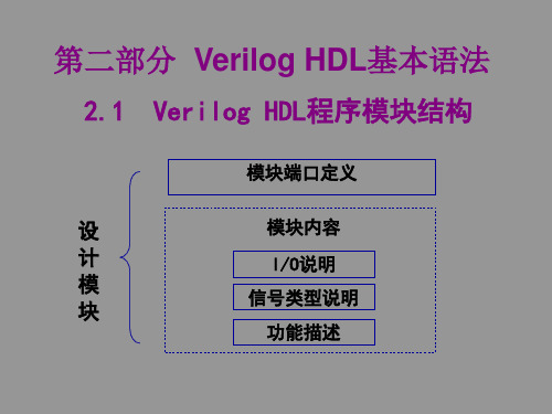
模块的结构
Verilog-HDL的基本设计单元是module(模块)。 一个module由两部分组成的:(一)描述端口; (二)描述逻辑功能,即定义输入是如何影响输出的。
端口定义
module block (a,b,d); input a,b; I/O说明 output d; wire c; 内部信号声明 assign c= a | b ; assign d= a & c; endmodule 功能定义
模块的测试
为什么没有端口?
由于测试模块是最顶 层模块,不会被其它 模块实例化。因此不 需要有端口。
测试模块常见的形式:
module t; reg …; wire…;
//被测模块输入变量类型定义 //被测模块输出变量类型定义
Testedmd m(.in1(ina), .in2(inb), .out1(outa), .out2(outb) ); //被测模块的实例引用 initial begin …; …; …; end … … //产生测试信号 always #delay begin …; end … … //产生测试信号
module MUX2_1_test;
// Data type declaration module MUX2_1 (out, a, b, sel); …….. endmodule
// Instantiate modules
MUX2_1 mux (out, a, b, sel); // Apply stimulus
从例子中可以看出整个Verilog-HDL描述是嵌套在 module和endmodule声明语句里的。
简单的 Verilog-HDL 模块
例3-2: //比较器 module compare ( equal,a,b ); output equal; // 输出信号equal input [1:0] a,b; // 输入信号a,b assign equal=(a==b)?1:0; endmodule
例3-1: // 三位加法器 module adder ( count, sum, a, b, cin ); input [2:0] a,b; // 加数和被加数 input cin; // 进位输入,即:从低位来的进位 output count; // 进位输出,即:向高位的进位 output [2:0] sum; // 和 assign {count,sum} = a+b+cin; endmodule // 连接运算符
DUT 被测器件 (device under test)
module MUX2_1 (out, a, b, sel); // Port declarations 注释行 output out; input a, b, sel; wire sel_, a1, b1;
a, b, sel是输入端口,out是输 出端口。所有信号通过这些端口从 模块输入/输出。 另一个模块可以通过模块名及 端口说明使用多路器。实例化多路 器时不需要知道其实现细节。这正 是自上而下设计方法的一个重要特 点。模块的实现可以是行为级也可 以是门级,但并不影响高层次模块 对它的使用。
module mytri (out,in,enable); output out; input in, enable; assign out = enable? In : 'bz; endmodule
在这个例子中存在着 两个模块:模块trist1 调 用模块 mytri 的实例元件 tri_inst。
模块 trist1 是上层模 块。模块 mytri 则被称为 子模块。 通过这种结构性模块 构造可构成特大型模块。
简单的 Verilog-HDL 模块
Verilog-HDL 描述是由模块构成的。模块是可以进行
层次嵌套的。正因为如此 , 才可以将大型的数字电路 设计分割成不同的小模块来实现特定的功能 , 最后通 过顶层模块调用子模块来实现整体功能。 每个模块要进行端口定义,并说明输入输出口,然后对 模块的功能进行行为逻辑描述。 Verilog-HDL描述的书写格式自由,一行可以写几个语 句,一个语句也可以分写多行。 除了endmodule 语句外 , 每个语句和数据定义的最后 必须有分号。 可以用 /*.....*/ 和 //... 对 Verilog-HDL 描述的任何部分 作注释。一个好的、有使用价值的描述都应当加上必 要的注释,以增强程序的可读性和可维护性。
// The netlist not (sel_, sel); and (a1, a, sel_); and (b1, b, sel); or (out, a1, b1); endmodule
多路器由关键 词module和 end 本单元的 实例
module(模块)
module是层 次化设计的基 本构件 逻辑描述放在 module内部
module能够表示: – 物理块,如IC或ASIC单元 – 逻辑块,如一个CPU设计的ALU部分 – 整个系统 每一个模块的描述从关键词module开始,有一个名称(如 SN74LS74,DFF,ALU等等),由关键词endmodule结束。