ATEN KVM 多电脑切换器 用户手册
- 格式:pdf
- 大小:313.85 KB
- 文档页数:16
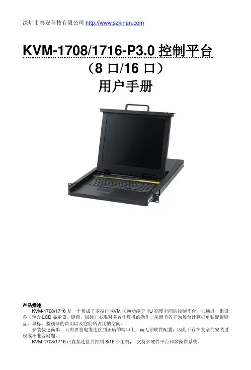
深圳市秦安科技有限公司KVM-1708/1716-P3.0控制平台(8口/16口)用户手册产品描述KVM-1708/1716是一个集成了多端口KVM切换功能于1U高度空间的控制平台,它通过一组设备(包含LCD显示器、键盘、鼠标)实现对多台计算机的操作。
从而节省了为每台计算机单独配置键盘、鼠标、监视器的费用以及它们所占用的空间。
安装快速简单,只需要将电缆连接到正确的端口上,而无须软件配置,因此不存在复杂的安装过程或不兼容问题。
产品特性●17” LCD TFT 液晶显示屏,高亮度,高清晰,高分辨率显示●1U 高度,适应于19”标准机柜安装,金属结构●超薄键盘99键,带数字小键盘,标准PS/2接口●采用触摸板鼠标,高分辨率,高灵敏度。
2个功能按键和滚轮功能(触摸板右边横条区域为滚轮功能区),符合PS/2 标准接口切换器功能●可直接连接8/16台电脑并实现切换操作●警音提示切换完成●无需安装附加软件,通过OSD菜单或热键操作,非常容易地在多台电脑间切换●切换电脑时,会自动记录并存储键盘、鼠标原有的工作状态●在自动扫描(auto-scan)模式下鼠标可正常使用●DDC模拟功能- 每台服务器的视讯设定会自动调整至屏幕显示的最佳状态●只用鼠标即可完成主机间的切换操作●具有热插拔功能(直接增加或移除主机而无需关闭KVM电源)外观图1-1.1整体外观尺寸图前视图(见图1-1.2)图1-1.2 KVM-1708前视图1.液晶显示屏2.后挂耳导槽3.LCD OSD控制键4.键盘5.前挂耳6.触摸鼠标7.拉手8.锁扣9.显示面板后视图(见图1-1.3)图1-1.3 KVM-1708后视图1 PC连接端口: 8个端口(集成VGA/键盘/鼠标信号输入端)2 电源输入插座(AC 或DC)3 电源开关4 接地螺钉5 Console : 外接显示器使用6 Update前视图(见图1-1.4)图1-1.4 KVM-1716 前视图1.液晶显示屏2.后挂耳导槽3.LCD OSD控制键4.键盘5.前挂耳6.触摸鼠标7.拉手8.锁扣9.显示面板后视图(见图1-1.5)图1-1.5 KVM-1716 后视图1 PC连接端口: 16个端口(集成VGA/键盘/鼠标信号输入端)2 电源输入插座(AC or DC)3 电源开关4 接地螺钉5 Console : 外接显示器使用6 Update机架安装KVM-1708/1716控制平台符合标准19”机柜的安装要求,由前向后安装,后挂耳插入导槽内,安装好后,锁紧前后挂耳螺丝。
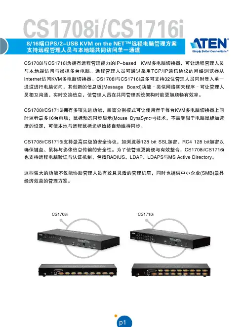
p1CS1708i 与CS1716i 为拥有远程管理能力的IP-based KVM多电脑切换器,可让远程管理人员与本地端访问与操控多台电脑。
远程管理人员可通过采用TCP/IP通讯协议的网络浏览器从Intern e t访问KVM多电脑切换器。
CS1708i 与CS1716i最多可支持32位管理人员同时登入单一通道进行电脑访问,其创新的信息板(M essage Boa r d )功能–类似网络聊天程序–可让管理人员相互沟通、实时交换信息,使管理人员在共同管理系统架构时能更加顺畅有效率。
CS1708i/CS1716i 拥有多项先进功能,画面分割模式可让使用者于每台KVM 多电脑切换器上同时监看最多16台电脑;鼠标动态同步显示(Mouse Dy na Sy n c T M )技术,不需受限于电脑鼠标加速度的设定,可使本地与远程鼠标光标始终自动维持同步。
CS1708i/CS1716i 支持最高层级的安全协议,如浏览器128 bi t SSL 加密、RC4 128 bi t加密以确保键盘、鼠标与影像信息传输的安全性。
为了使管理更简便与有效整合,CS1708i/CS1716i 也支持远程电脑验证与认证机制,包括RAD I U S、LD AP、LD APS与MS Act ive Di r e ct o ry。
这些强大的功能不仅能协助管理人员有效且灵活的管理机房,同时也提供中小企业(SM B )最具经济效益的管理方案。
p2管理可通过前端面板按键、热键与支持多国语言的OS D屏幕选单进行电脑选择与切换 允许32位使用者同时登入多国语言的web使用者接口,可支持本地端与远程OS D以树状架构显示所连接的电脑 可调整影像质量以弹性适应不同的网络环境 自动扫描功能可监看使用者所选择的电脑状态支持广播模式,可同时于所有选择的电脑上进行指令操作(如安装软件、系统关闭…等) 支持固件更新支持备份与复原组态设定,以及使用者账号设定 事件日志功能开启/关闭浏览器访问功能简易使用的接口本地控制端的浏览器与AP 图形化使用者接口(GUI)搭配OS D屏幕选单,可提供强大、直觉式、人性化与多国语言的接口,以减少使用者学习时间并提高产能 支持多平台的客户端系统 (W indow s, Mac OS X, Linux, Sun) 支持多种浏览器接口 (IE, Mozilla, Fir e fox, Safari, Op e ra, N e tscap e ) 当设备顺序改变时,可自动重新配置连接端口名称画面分割模式可让使用者从单一屏幕同时监看不同的电脑状态–每个所选的 电脑影像输出可显示在一个分割的屏幕上–使用者可轻松选择欲检视的画面数目 支持W indow s clie nt 与Jav a clie nt 软件;Jav a clie nt 可在所有的操作系统下运作先进的安全机制通过RC 4 128 b it 加密技术以确保键盘、鼠标、屏幕信号传输的安全性 128 b it SS L浏览器访问 双层密码保护机制–最多可允许64位使用者账号拥有各自的数据设定 支持外部(远程)认证机制–R ADIUS 、L DAP 、L DAPS 、MS Act ive Dir e ctory 支持IP/MA C过滤功能 本地端与远程登入及验证机制虚拟远程桌面窗口信息板功能可让已登入的使用者相互沟通,并可允许其中一位使用者单独控管KVM 功能支持鼠标动态同步显示(Mous e DynaSyncTM )技术 支持多国语言屏幕(on-scr ee n)键盘 BIOS 层级访问硬件8/16端口支持远程访问的KVM 多电脑切换器–可通过单一KVM 控制端监控多达8/16台电脑 可菊链串接额外15台KVM 多电脑切换器–单一控制端可控管多达128台(C S1708i)或256(C S 1716i)台电脑*在菊链串接的架构下,可自动侦测装置机台位置并显示于前端面板的LE D指示灯上,无须手动进行DIP 设定 支持热插拔–毋须关闭电源即可直接增加或移除电脑支持IP v6NEW可通过前端面板按键、热键与支持多国语言的OS D屏幕选单进行电脑选择与切换 允许32位使用者同时登入 多国语言的web使用者接口,可支持本地端与远程OS D以树状架构显示所连接的电脑 可调整影像质量以弹性适应不同的网络环境 自动扫描功能可监看使用者所选择的电脑状态 支持广播模式,可同时于所有选择的电脑上进行指令操作(如安装软件、系统关闭…等) 支持固件更新 支持备份与复原组态设定,以及使用者账号设定 事件日志功能 开启/关闭浏览器访问功能简易使用的接口 本地控制端的浏览器与AP 图形化使用者接口(GUI)搭配OS D屏幕选单,可提供强大、直觉式、人性化与多国语言的接口,以减少使用者学习时间并提高产能 支持多平台的客户端系统 (W indow s, Mac OS X, Linux, Sun) 支持多种浏览器接口 (IE, Mozilla, Fir e fox, Safari, Op e ra, N e tscap e ) 当设备顺序改变时,可自动重新配置连接端口名称 画面分割模式可让使用者从单一屏幕同时监看不同的电脑状态–每个所选的 电脑影像输出可显示在一个分割的屏幕上–使用者可轻松选择欲检视的画面数目 支持W indow s clie nt 与Jav a clie nt 软件;Jav a clie nt 可在所有的操作系统下运作先进的安全机制 通过RC 4 128 b it 加密技术以确保键盘、鼠标、屏幕信号传输的安全性 128 b it SS L浏览器访问 双层密码保护机制–最多可允许64位使用者账号拥有各自的数据设定 支持外部(远程)认证机制–R ADIUS 、L DAP 、L DAPS 、MS Act ive Dir e ctory 支持IP/MA C过滤功能 本地端与远程登入及验证机制虚拟远程桌面窗口 信息板功能可让已登入的使用者相互沟通,并可允许其中一位使用者单独控管KVM 功能 支持鼠标动态同步显示(Mous e DynaSync TM )技术 支持多国语言屏幕(on-scr ee n)键盘 BIOS 层级访问硬件 8/16端口支持远程访问的KVM 多电脑切换器–可通过单一KVM 控制端监控多达8/16台电脑 可菊链串接额外15台KVM 多电脑切换器–单一控制端可控管多达128台(C S1708i)或256(C S 1716i)台电脑* 在菊链串接的架构下,可自动侦测装置机台位置并显示于前端面板的LE D指示灯上,无须手动进行DIP 设定 支持热插拔–毋须关闭电源即可直接增加或移除电脑p3简易使用的接口虚拟远程桌面优异的视频质量分割画面模式信息板功能鼠标动态同步显示Mouse DynaSyncT M 前端面板的USB Hub可供连接的电脑进行外围设备分享 双接口–具备自动侦测接口的功能,可支持配备PS/2或USB键盘及鼠标的电脑 USB / PS/2键盘与鼠标仿真功能–即使控制端在不同电脑之间切换,仍可确保电脑正常开机运作 支持多媒体USB键盘(PC、Mac与Sun) 高视频分辨率–本地端支持2048 x 1536,DDC2B;远程支持1600 x1200@60Hz / 24位色深屏幕动态显示技术(Video DynaSync T M )–储存控制端屏幕E DID(延伸显示辨识码),保持最佳屏幕显示分辨率可安装于19寸(1U)机架空间*兼容的KVM多电脑切换器:AC S1208A、A C S 1216A、CS1708、CS1716、CS 1708A 、CS 1716A 、K H1508、KH1516浅显易懂的图形化使用者接口使访问、组态设定与操作更轻松简易。
kvm切换器使用方法KVM切换器使用方法。
KVM切换器是一种非常方便的设备,它可以让用户同时控制多台电脑,而无需使用多个键盘、鼠标和显示器。
在本文中,我们将介绍KVM切换器的使用方法,以便用户能够更好地利用这一设备。
首先,使用KVM切换器之前,我们需要准备好以下设备,KVM切换器本身、多台电脑、键盘、鼠标和显示器。
确保所有设备都处于正常工作状态,并且连接线缆齐全。
接下来,我们将按照以下步骤来正确地使用KVM切换器:1. 将KVM切换器连接到电源,并确保其处于工作状态。
一般来说,KVM切换器会有一个电源指示灯,当其点亮时表示设备已经开启。
2. 将多台电脑分别连接到KVM切换器的相应端口上。
通常情况下,KVM切换器会有标有“PC1”、“PC2”等端口,用户只需将各台电脑连接到相应的端口上即可。
3. 将键盘、鼠标和显示器连接到KVM切换器的相应端口上。
同样地,KVM切换器会有标有“Keyboard”、“Mouse”和“Monitor”的端口,用户只需将这些设备连接到相应的端口上即可。
4. 确保所有设备连接正确后,打开KVM切换器。
在KVM切换器上,通常会有一个按钮或者转盘,用户可以通过按下按钮或者旋转转盘来切换不同的电脑。
在切换电脑时,用户只需按下按钮或者旋转转盘即可完成切换。
5. 最后,用户可以通过键盘和鼠标来控制所选择的电脑,而显示器上也会显示所选择的电脑的画面。
当需要切换至另一台电脑时,只需重复步骤4即可。
需要注意的是,不同型号的KVM切换器可能会有一些细微的差异,因此在使用KVM切换器时,最好先阅读一下相应的使用手册,以确保能够正确地操作设备。
总的来说,KVM切换器是一种非常实用的设备,它可以大大提高用户的工作效率,尤其是需要频繁切换多台电脑时。
通过本文所介绍的使用方法,相信用户能够更好地利用KVM切换器,从而更轻松地完成工作。
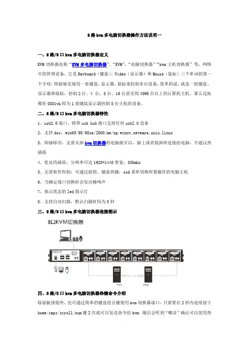
8路kvm多电脑切换器操作方法说明一一、8路/8口kvm多电脑切换器定义KVM切换器也称“KVM多电脑切换器”、“KVM”、“电脑切换器”“kvm主机切换器”等,网络中的管理设备,它是Keyboard(键盘)、Video(显示器)和Mouse(鼠标)三个单词的第一个字母。
即能够实现用一套键盘、显示器、鼠标来控制多台设备。
简单的说,就是一组键盘、显示器和鼠标,控制2台、4 台、8台、16台甚至到4096台以上的计算机主机。
那么迈拓维矩0801vk即为1套键鼠显示器控制8台主机的设备。
二、8路/8口kvm多电脑切换器特性1、usb2.0端口,特带usb hub接口支持任何usb2.0设备2、支持dos,win95/98/98se/2000/me/xp.winnt,netware,unix,linux3、即插即用,无需关掉kvm切换器的电脑就可以,插上或者拔掉所连接的电脑,不建议热插拔4、优良的画质:分辨率可达1920*1440带宽:350mhz5、无需软件控制:可通过按钮、键盘热键,osd菜单切换所要操作的电脑主机6、当确定端口切换时会发出蜂鸣声7、指示状态的led指示灯8、支持自动扫描,默认扫描时间为5秒三、8路/8口kvm多电脑切换器连接图示四、8路/8口kvm多电脑切换器热键命令介绍除面板按钮外,也可通过简单的键盘组合键使用kvm切换器端口,只需要在2秒内连续按下home/caps/scroll/num键2次就可以发送命令给kvm,随后会听到“嘟音”确认可以使用热键命令了,此产品有多个模式可选择。
【home】+【home】是产品默认模式,当您不想用这个模式是可选择别的命令模式,一下是设定不同热键模式默认模式命令【home】+【home】+I+数字+enter 设置自动扫描没端口停留时间,数字为5~999秒。
如您想使用caps模式时请先按【home】+【home】+caps,这时进入了caps模式【caps】+【caps】+I+数字+enter 设置自动扫描没端口停留时间,数字为5-999秒五、osd菜单操作热键功能也可以在osd下实现,从osd菜单下选择一个热键端口可以按以下操作:连击(home+home+enter)激活osd菜单:注意:如果osd正在使用,当您在主菜单上可以直接点击而无需连击(home)User:admin:依据选择的用户,红色字符会自动修改C :00:级联显示,00表示第一级,01表示第2级Kvm :16 ports:端口数量8:表示8口kvm!:表示当前选择的端口T:表示标示自动扫描的端口(scan tag)ON:表示此端口正常连接了usb端口菜单设置F1:修改端口名称F2:设置需要扫描的端口,配合autoscan mode 2 tag 使用(按F2打开或者关闭扫描标示“T”,如下图2显示)F3:系统设置F4:扫描端口F6:设置分配非管理员用户的主机(用户1-7可以操作哪些主机)F7:用户登入设置注:F1.F2.F3.F4. F6.F7是需要按键盘上面的相应按键F1:修改主机名称界面如下:注:可以随意更改主机的名称,使用键盘上下键控制,当你需要更改主机名称时按键盘enter 就可以更改了。
USB 2.0 DVI KVM ExtenderCE610User ManualCE610 User ManualEMC InformationFEDERAL COMMUNICATIONS COMMISSION INTERFERENCE STATEMENT: This equipment has been tested and found to comply with the limits for a Class A digital device, pursuant to Part 15 of the FCC Rules. These limits are designed to provide reasonable protection against harmful interference when the equipment is operated in a commercial environment. This equipment generates, uses, and can radiate radio frequency energy and, if not installed and used in accordance with the instruction manual, may cause harmful interference to radio communications. Operation of this equipment in a residential area is likely to cause harmful interference in which case the user will be required to correct the interference at his own expense.The device complies with Part 15 of the FCC Rules. Operation is subject to the following two conditions: (1) this device may not cause harmful interference, and (2) this device must accept any interference received, including interference that may cause undesired operation.FCC Caution: Any changes or modifications not expressly approved by the party responsible for compliance could void the user's authority to operate this equipment.CE Warning: This is a class A product. In a domestic environment this product may cause radio interference in which case the user may be required to take adequate measures.Suggestion: Shielded twisted pair (STP) cables must be used with the unit to ensure compliance with FCC & CE standards.KCC Statement유선 제품용 / A급 기기 (업무용 방송 통신 기기)이 기기는 업무용(A급) 전자파적합기기로서 판매자 또는 사용자는 이점을 주의하시기 바라며, 가정 외의 지역에서 사용하는 것을 목적으로 합니다.RoHSThis product is RoHS compliant.CE610 User Manual SJ/T 11364-2006CE610 User ManualUser InformationOnline RegistrationBe sure to register your product at our online support center:International Telephone SupportFor telephone support, call this number:International886-2-8692-6959China86-10-5255-0110Japan81-3-5615-5811Korea82-2-467-6789North America1-888-999-ATEN ext 4988United Kingdom44-8-4481-58923User NoticeAll information, documentation, and specifications contained in this manual are subject to change without prior notification by the manufacturer. The manufacturer makes no representations or warranties, either expressed or implied, with respect to the contents hereof and specifically disclaims any warranties as to merchantability or fitness for any particular purpose. Any of the manufacturer's software described in this manual is sold or licensed as is. Should the programs prove defective following their purchase, the buyer (and not the manufacturer, its distributor, or its dealer), assumes the entire cost of all necessary servicing, repair and any incidental or consequential damages resulting from any defect in the software.The manufacturer of this system is not responsible for any radio and/or TV interference caused by unauthorized modifications to this device. It is the responsibility of the user to correct such interference.The manufacturer is not responsible for any damage incurred in the operation of this system if the correct operational voltage setting was not selected prior to operation. PLEASE VERIFY THAT THE VOLTAGE SETTING IS CORRECT BEFORE USE.CE610 User Manual Package ContentsThe CE610 package consists of:1CE610L USB 2.0 DVI KVM Extender (Local Unit)1CE610R USB 2.0 DVI KVM Extender (Remote Unit)1Custom DVI 1.8 m Cable1 1.8 m USB Cable2Power Adapters1Mounting Kit1User Instructions*Check to make sure that all the components are present and that nothing got damaged in shipping. If you encounter a problem, contact your dealer.Read this manual thoroughly and follow the installation and operation procedures carefully to prevent any damage to the unit, and/or any of the devices connected to it.*Features may have been added to the CE610 since this manual was published. Please visit our website to download the most up-to-date version of the manual.© Copyright 2015 ATEN® International Co., Ltd.Manual Date: 2015-11-02ATEN and the ATEN logo are registered trademarks of ATEN International Co., Ltd. All rights reserved.All other brand names and trademarks are the registered property of their respective owners.CE610 User ManualContentsEMC Information. . . . . . . . . . . . . . . . . . . . . . . . . . . . . . . . . . . . . . . . . . . . . ii RoHS . . . . . . . . . . . . . . . . . . . . . . . . . . . . . . . . . . . . . . . . . . . . . . . . . . . . . ii SJ/T 11364-2006 . . . . . . . . . . . . . . . . . . . . . . . . . . . . . . . . . . . . . . . . . . . .iii User Information. . . . . . . . . . . . . . . . . . . . . . . . . . . . . . . . . . . . . . . . . . . . .iv Online Registration . . . . . . . . . . . . . . . . . . . . . . . . . . . . . . . . . . . . . . . .iv Telephone Support . . . . . . . . . . . . . . . . . . . . . . . . . . . . . . . . . . . . . . . .iv User Notice. . . . . . . . . . . . . . . . . . . . . . . . . . . . . . . . . . . . . . . . . . . . . .iv Package Contents . . . . . . . . . . . . . . . . . . . . . . . . . . . . . . . . . . . . . . . . . . . v About this Manual. . . . . . . . . . . . . . . . . . . . . . . . . . . . . . . . . . . . . . . . . . . vii Conventions . . . . . . . . . . . . . . . . . . . . . . . . . . . . . . . . . . . . . . . . . . . . . . .viii Product Information . . . . . . . . . . . . . . . . . . . . . . . . . . . . . . . . . . . . . . . . .viii Chapter 1.IntroductionOverview. . . . . . . . . . . . . . . . . . . . . . . . . . . . . . . . . . . . . . . . . . . . . . . . . . .1 Features . . . . . . . . . . . . . . . . . . . . . . . . . . . . . . . . . . . . . . . . . . . . . . . . . . .2 Requirements. . . . . . . . . . . . . . . . . . . . . . . . . . . . . . . . . . . . . . . . . . . . . . .3 Consoles. . . . . . . . . . . . . . . . . . . . . . . . . . . . . . . . . . . . . . . . . . . . . . . .3 Computers. . . . . . . . . . . . . . . . . . . . . . . . . . . . . . . . . . . . . . . . . . . . . . .3 Cables. . . . . . . . . . . . . . . . . . . . . . . . . . . . . . . . . . . . . . . . . . . . . . . . . .3 Operating Systems . . . . . . . . . . . . . . . . . . . . . . . . . . . . . . . . . . . . . . . .4 Components. . . . . . . . . . . . . . . . . . . . . . . . . . . . . . . . . . . . . . . . . . . . . . . .5 CE610L (Local Unit) Front and Rear View . . . . . . . . . . . . . . . . . . . . . .5 CE610R (Remote Unit) Front and Rear View. . . . . . . . . . . . . . . . . . . .6 Chapter 2.Hardware SetupRack Mounting . . . . . . . . . . . . . . . . . . . . . . . . . . . . . . . . . . . . . . . . . . . . . .7 Installation. . . . . . . . . . . . . . . . . . . . . . . . . . . . . . . . . . . . . . . . . . . . . . . . . .9 Grounding. . . . . . . . . . . . . . . . . . . . . . . . . . . . . . . . . . . . . . . . . . . . . . .9 Setting Up. . . . . . . . . . . . . . . . . . . . . . . . . . . . . . . . . . . . . . . . . . . . . .11 Installation Diagram . . . . . . . . . . . . . . . . . . . . . . . . . . . . . . . . . . . . . .12 Chapter 3.OperationLED Display . . . . . . . . . . . . . . . . . . . . . . . . . . . . . . . . . . . . . . . . . . . . . . .13 CE610L (Local Unit) and CE610R (Remote Unit). . . . . . . . . . . . . . . .13 AppendixSafety Instructions . . . . . . . . . . . . . . . . . . . . . . . . . . . . . . . . . . . . . . . . . .14 General. . . . . . . . . . . . . . . . . . . . . . . . . . . . . . . . . . . . . . . . . . . . . . . .14 Mounting. . . . . . . . . . . . . . . . . . . . . . . . . . . . . . . . . . . . . . . . . . . . . . .16 Technical Support. . . . . . . . . . . . . . . . . . . . . . . . . . . . . . . . . . . . . . . . . . .17 International . . . . . . . . . . . . . . . . . . . . . . . . . . . . . . . . . . . . . . . . . . . .17 North America. . . . . . . . . . . . . . . . . . . . . . . . . . . . . . . . . . . . . . . . . . .17CE610 User Manual Specifications . . . . . . . . . . . . . . . . . . . . . . . . . . . . . . . . . . . . . . . . . . . . . .18 Limited Warranty. . . . . . . . . . . . . . . . . . . . . . . . . . . . . . . . . . . . . . . . . . . .19CE610 User ManualAbout this ManualThis User Manual is provided to help you get the most from your system. It covers all aspects of installation, configuration and operation. An overview of the information found in the manual is provided below.Chapter 1, Introduction, introduces you to the CE610 system. Its purpose, features and benefits are presented, and its front and back panel components are described.Chapter 2, Hardware Setup, describes the steps that are necessary to quickly and safely set up your installation.Chapter 3, Operation, explains the fundamental concepts involved in operating the CE610An Appendix, provides specifications and other technical information regarding the CE610.CE610 User Manual Conventions This manual uses the following conventions:Product InformationFor information about all ATEN products and how they can help you connect without limits, visit ATEN on the Web or contact an ATEN AuthorizedReseller. Visit ATEN on the Web for a list of locations and telephone numbers:MonospacedIndicates text that you should key in.[ ]Indicates keys you should press. For example, [Enter] means topress the Enter key. If keys need to be chorded, they appeartogether in the same bracket with a plus sign between them:[Ctrl+Alt].1.Numbered lists represent procedures with sequential steps.♦Bullet lists provide information, but do not involve sequential steps.→Indicates selecting the option (on a menu or dialog box, forexample), that comes next. For example, Start → Run means toopen the Start menu, and then select Run .Indicates critical information.International North America Chapter 1Introduction OverviewThe CE610 USB 2.0 DVI KVM Extender is a DVI and USB Extender that supports ExtremeUSB® and HDBaseT technology. The CE610 USB 2.0 DVI KVM Extender can extend DVI and USB 2.0 signals up to 300 ft (100 m) from the source using a single Cat 5e/6 cable. The CE610 is equipped with USB connectors which allow you to extend any USB device between the units. The USB functionality provides not only peripheral sharing but also provides support for touch panel control and file transfer. The CE610 is ideal for transportation centers, medical facilities, and shopping malls, industrial kiosks and for syncing files and folders between portable and desktop computers. The CE610 allows access to a computer system from a remote console (USB keyboard, monitor, and mouse). Because it allows access to a computer system from a remote console, the CE610 is perfect for use in any type of installation where you need to place the console where it is conveniently accessible, but you want the system equipment to reside in a safe location – away from the dust and dirt of the factory floor, or the harsh environmental influence of a construction site, for example. This allows users to deploy system equipment over large distances.The CE610 is useful for control and security purposes, where you can have the system unit in a secure area at the same time that you put the console in the most convenient location for user access. This is ideal for managing highly confidential data systems.The CE610 improves on previous designs by: 1) using inexpensive Cat 5e cable instead of bulkier, more expensive, standard DVI cables, for a much neater, more convenient, more reliable data transfer connection; and 2) featuring a custom ASIC to ensure the utmost in reliability and compatibility. Setup is as easy as can be – simply connect the computer system box; run the Cat 5e cable up to 100 meters to the Remote Unit; and plug the remote console into the Remote Unit.CE610 User ManualFeaturesUses a single Cat 5e cable to connect the local and remote unitsAllows access to a computer or KVM installation from a remote console Superior Video Quality – up to 1920 x 1200 @ 60 Hz at 100 mSupports HDBaseT connectivity technologyTransparent USB Support – supports all USB 2.0 High Speed device*Extends local PC Video/Keyboard/Mouse to Remote sideBuilt-in 8KV/15KV ESD protection (Contact voltage 8KV; Air voltage 15KV)ExtremeUSB® - supports transparent USB 2.0 signals and true plug-and-play (no software or drivers required)USB 2.0 Support* – connects devices such as keyboard, mouse, flash drive, printer, touch panel, USB 1.1 web cameras and other USB devices which require moderate amounts of bandwidthWorks with all major operating systems: Windows®, OS X®, and Linux®*Note: The CE610 supports a maximum combined USB transfer rate of 30 Mbps for attached USB devices.Chapter 1. Introduction RequirementsConsolesA DVI-D monitor capable of the highest resolution you will be using onany computer in the installation.A USB keyboardA USB mouseComputersThe following equipment must be installed on each computer that is to be connected to the system:A DVI-D / DVI-I port2 USB ports for the mouse and keyboardMicrophone and speaker ports (optional)CablesFor optimal signal integrity, and to simplify the layout, we strongly recommend that you use the high quality custom DVI Cable that isprovided with this package.Cat 5e cable is required to connect the Local and Remote CE610 Units.Cable of a lower standard will result in degrading of the video signal. We strongly recommend using Cat 5e cables.For better quality over longer distances, we suggest using 2L-2801 (350 MHz) Low Skew CableMaximum Cable DistancesConnection Distance Computer to Local Unit (CE610L) 1.8 m100 mLocal Unit (CE610L)to Remote Unit (CE610R)Remote Unit (CE610R) to monitor 5 mCE610 User ManualOperating SystemsSupported operating systems are shown in the table, below:OS Version Windows2000 and higherLinux RedHat9.0 and higherSuSE10 / 11.1 and higherDebian 3.1 / 4.0Ubuntu7.04 / 7.10UNIX FreeBSD 5.5 / 6.1 / 6.2Novell Netware 6.0 and higherMac OS 10.1 and higher Note:The CE610 does not support OS that do not support USB.Chapter 1. IntroductionComponentsCE610L (Local Unit) Front and Rear ViewponentDescription1LEDsThe CE610L has four LEDs to indicate operating status – Power, Link, USB, and Video.2Firmware Upgrade PortThe Firmware Upgrade Port is reserved for technical support. If you would like to upgrade the unit’sfirmware yourself, please contact your ATEN dealer.3Unit to Unit Port The Cat 5e cable that connects the Local and Remote Units plugs in here.4DVI-D In Port Connect a DVI cable from a computer to this port.5USB Type B Input The USB cable from your computer or USB hub plugs in here.6Power JackThe cable from the Power adapter connects here.CE610 User ManualCE610R (Remote Unit) Front and Rear Viewponent Description1LEDs The CE610R has four LEDs to indicate operatingstatus – Power, Link, USB, and Video.2Firmware Upgrade Port The Firmware Upgrade Port is reserved for technical support. If you would like to upgrade the unit’s firmware yourself, please contact your ATEN dealer.3Unit to Unit Port The Cat 5e cable that connects the Local and RemoteUnits plugs in here.4DVI-D Out Port Connect a DVI monitor to this port.5USB Type A Ports Your USB 2.0 devices plug in here.6Power Jack The cable from the Power adapter connects here.Chapter 2Hardware Setup1.Important safety information regarding the placement of thisdevice is provided on page14. Please review it beforeproceeding.2.Make sure that the power to all devices connected to theinstallation are turned off. You must unplug the power cords ofany computers that have the Keyboard Power On function.Rack MountingFor convenience and flexibility, the CE610 can be mounted on system racks. To rack mount a unit do the following:ing the screws provided in the Mounting Kit, screw the mountingbracket into the top or bottom of the unit as show in the diagram below:CE610 User Manual2.Screw the bracket into any convenient location on the rack.Note:These screws are not provided. We recommend that you use M5 x 12 Phillips Type I cross, recessed type screws.Chapter 2. Hardware Setup InstallationGroundingTo prevent damage to your installation it is important that all devices are properly grounded.e a grounding wire to ground both units by connecting one end of thewire to the grounding terminal, and the other end of the wire to a suitable grounded object.2.Make sure that the computer that the Local Unit connects to and themonitor that the Remote Unit connects to are properly grounded.CE610 User Manual3.For increased grounding protection, use STP (shielded twisted pair) cableto connect the Local and Remote Units. There are two methods that can be used:a)In addition to the eight paired wires, STP cable also contains agrounding wire. Solder this wire to the RJ-45 connector as shown in the diagram below:b)The second method is to use the STP cable shielding for grounding. Inthis case, make sure that the shielding makes tight contact with the top inside of the RJ-45 connector as shown in the diagram below:In either case, make sure that the sides of the RJ-45 connector make tight contact with the grounding contacts on the sides of the RJ-45 socket as shown in the diagram below:Chapter 2. Hardware SetupSetting UpSetting up the CE610 DVI KVM Extender system is simply a matter of plugging in the cables. Make sure that all the equipment to be connected are powered off. Refer to the installation diagram on the following page and do the following:1.Connect the USB cable supplied with the package to the USB Type B porton the Local Unit (CE610L). Plug the other end of the cable into a USB Type A port on the local computer.2.Connect the DVI-D cable supplied with the package to the DVI-D inputport located on the Local Unit (CE610L). Plug the other end of the cable into the DVI port on the local computer.3.Plug either end of the Cat 5e cable into the CE610's Unit to Unit R-J45port. Plug the other end of the Cat 5e cable into the Unit to Unit RJ-45 port of the Remote Unit (CE610R).4.Plug one of the power adapters (supplied with this package) into a powersource; plug the adapter's power cable into the CE610L's Power Jack. e a DVI cable to connect the DVI-D output port on the Remote Unit(CE610R) to your monitor.6.Plug the cables from the remote USB devices (mouse, keyboard, etc.), intotheir respective USB ports on the Remote Unit CE610R.7.Plug the second power adapter (supplied with this package) into a powersource; plug the adapter's power cable into the CE610R's Power Jack.CE610 User Manual Installation DiagramChapter 3Operation LED DisplayThe CE610 Local and Remote Units have front panel LEDs to indicate their operating status, as shown in the tables, following:CE610L (Local Unit) and CE610R (Remote Unit)LED IndicationPower (Green)Lights steadily to indicate that the system is receiving power.Link (Green) Lights steadily to indicate that the connection to the Local andRemote units is ok.OFF when there is a problem with the connection.USB (Green) Lights to indicate that the USB connection to the host com-puter is working.Flashes green to indicate that the host is in suspend mode.OFF indicates that the link is inactive.Video (Green) Flashes to indicate normal video activity.Lights steadily to indicate HDCP video activity.OFF indicates that there is no video activity.Appendix Safety InstructionsGeneralRead all of these instructions. Save them for future reference.Follow all warnings and instructions marked on the device.This product is for indoor use only.Do not place the device on any unstable surface (cart, stand, table, etc.). If the device falls, serious damage will result.Do not use the device near water.Do not place the device near, or over, radiators or heat registers.The device cabinet is provided with slots and openings to allow for adequate ventilation. To ensure reliable operation, and to protect against overheating, these openings must never be blocked or covered.The device should never be placed on a soft surface (bed, sofa, rug, etc.) as this will block its ventilation openings. Likewise, the device should not be placed in a built in enclosure unless adequate ventilation has been provided. Never spill liquid of any kind on the device.Unplug the device from the wall outlet before cleaning. Do not use liquid or aerosol cleaners. Use a damp cloth for cleaning.The device should be operated from the type of power source indicated on the marking label. If you are not sure of the type of power available,consult your dealer or local power company.The device is designed for IT power distribution systems with 230V phase-to-phase voltage.To prevent damage to your installation, it is important that all devices are properly grounded.The device is equipped with a 3-wire grounding type plug. This is a safety feature. If you are unable to insert the plug into the outlet, contact your electrician to replace your obsolete outlet. Do not attempt to defeat the purpose of the grounding-type plug. Always follow your local/national wiring codes.Do not allow anything to rest on the power cord or cables. Route the power cord and cables so that they cannot be stepped on or tripped over.Appendix If an extension cord is used with this device make sure that the total of the ampere ratings of all products used on this cord does not exceed theextension cord ampere rating. Make sure that the total of all productsplugged into the wall outlet does not exceed 15 amperes.To help protect your system from sudden, transient increases and decreases in electrical power, use a surge suppressor, line conditioner, or un-interruptible power supply (UPS).Position system cables and power cables carefully; Be sure that nothing rests on any cables.Never push objects of any kind into or through cabinet slots. They may touch dangerous voltage points or short out parts resulting in a risk of fire or electrical shock.Do not attempt to service the device yourself. Refer all servicing to qualified service personnel.If the following conditions occur, unplug the device from the wall outlet and bring it to qualified service personnel for repair.The power cord or plug has become damaged or frayed.Liquid has been spilled into the device.The device has been exposed to rain or water.The device has been dropped, or the cabinet has been damaged.The device exhibits a distinct change in performance, indicating a need for service.The device does not operate normally when the operating instructions are followed.Only adjust those controls that are covered in the operating instructions.Improper adjustment of other controls may result in damage that willrequire extensive work by a qualified technician to repair.CE610 User ManualMountingBefore working on the rack, make sure that the stabilizers are secured to the rack, extended to the floor, and that the full weight of the rack rests on the floor. Install front and side stabilizers on a single rack or frontstabilizers for joined multiple racks before working on the rack.Always load the rack from the bottom up, and load the heaviest item in the rack first.Make sure that the rack is level and stable before extending a device from the rack.Use caution when pressing the device rail release latches and sliding a device into or out of a rack; the slide rails can pinch your fingers.After a device is inserted into the rack, carefully extend the rail into a locking position, and then slide the device into the rack.Do not overload the AC supply branch circuit that provides power to the rack. The total rack load should not exceed 80 percent of the branch circuit rating.Make sure that all equipment used on the rack – including power strips and other electrical connectors – is properly grounded.Ensure that proper airflow is provided to devices in the rack.Ensure that the operating ambient temperature of the rack environment does not exceed the maximum ambient temperature specified for theequipment by the manufacturer.Do not step on or stand on any device when servicing other devices in a rack.AppendixTechnical SupportInternationalFor online technical support – including troubleshooting, documentation, and software updates: For telephone support, Telephone Support , page ivNorth AmericaWhen you contact us, please have the following information ready beforehand: Product model number, serial number, and date of purchase.Your computer configuration, including operating system, revision level, expansion cards, and software. Any error messages displayed at the time the error occurred. The sequence of operations that led up to the error. Any other information you feel may be of help.Email Support ********************Online Technical SupportTroubleshooting Documentation Software Updates/supportTelephone Support 1-888-999-ATEN ext 4988CE610 User ManualSpecificationsFunction CE610L CE610R Connectors DVI In 1 x DVI-D Female(White)N/ADVI Out N/A 1 x DVI-D Female(White)USB 1 x USB Type B Female(White)3 x USB Type A Female(White)Power 1 x DC JackF/W Upgrade 1 x Mini-USBUnit to Unit 1 x RJ-45 Female (Black)LEDs Power 1 (Green) 1 (Green) Link 1 (Green) 1 (Green)USB 1 (Green) 1 (Green)Video 1 (Green) 1 (Green) USB Transfer Rate USB 2.0 (Up to 30 Mbps)Video1920 x 1200 @ 60Hz (100 m);Power Consumption DC 5V 15 W DC 5V 15W Environment Operating Temp.0–50ºCStorage Temp-20–60ºCHumidity0–80% RH, Non-condensingPhysical Properties Housing MetalWeight605 g615 g Dimensions (L x W x H)18.20 x 11.79 x 2.28 cmAppendixLimited WarrantyIN NO EVENT SHALL THE DIRECT VENDOR'S LIABILITY EXCEED THE PRICE PAID FOR THE PRODUCT FROM DIRECT, INDIRECT, SPECIAL, INCIDENTAL, OR CONSEQUENTIAL DAMAGES RESULTING FROM THE USE OF THE PRODUCT, DISK, OR ITS DOCUMENTATION.The direct vendor makes no warranty or representation, expressed, implied, or statutory with respect to the contents or use of this documentation, and especially disclaims its quality, performance, merchantability, or fitness for any particular purpose.The direct vendor also reserves the right to revise or update the device or documentation without obligation to notify any individual or entity of such revisions, or update. For further inquiries, please contact your direct vendor.。
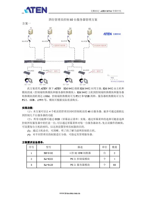
四位管理员控制60台服务器管理方案方案一此方案采用A TEN 旗下A TEN KM-0432级联KM-0432应用方案,KM-0432由主机和模块组成(控制端转换模块和服务器转换模块),KM-0432主机到控制端转换模块和服务器转换模块的距离达150M,控制端转换模块可为PS/2和USB两种,服务器转换模块可分为PS/2、SUB、13W3等,模块可根据实际需求购买。
实现功能:(1):本方案可以让4个机房的管理员同时控制机房的60台服务器,最多可通过级联达到控制几千台服务器的功能(2):所有功能都可通过OSD(屏幕显示菜单)实现。
通过屏幕菜单的选择可随意选择控制所有服务器中的任意一台;可以通过屏幕菜单对每一台服务器命名,免去误操作的麻烦;可设置每台主机的密码,以达到设置管理员权限的目的。
(3):通过主机命名,可清晰、明了的了解当前所控制的主机。
(4):对不同管理员的权限进行分级,可指定其管理服务器。
方案需求设备清单:此方案采用A TEN 旗下A TEN KM-0432级联CS-9138应用方案,KM-0432由主机和模块组成(控制端转换模块和服务器转换模块),KM-0432主机到控制端转换模块和服务器转换模块的距离达150M,控制端转换模块可为PS/2和USB两种,服务器转换模块可分为PS/2、SUB、13W3等,模块可根据实际需求购买。
CS-9138为一套PS/2接口的键盘、鼠标和显示器操作8台PS/2接口主机的单控多切换器。
实现功能:(1):本方案可以让4个机房的管理员同时控制机房的60台服务器,最多可通过级联达到控制几千台服务器的功能(2):所有功能都可通过OSD(屏幕显示菜单)实现。
通过屏幕菜单的选择可随意选择控制所有服务器中的任意一台;可以通过屏幕菜单对每一台服务器命名,免去误操作的麻烦;可设置每台主机的密码,以达到设置管理员权限的目的。
(3):通过主机命名,可清晰、明了的了解当前所控制的主机。

1-Local / Remote Share Access Single PortKVM over IP SwitchCN9000 / CN9600 / CN9950User ManualCN9000 / CN9600 / CN9950CN9000 / CN9600 / CN9950 User Manual iiEMC InformationFEDERAL COMMUNICATIONS COMMISSION INTERFERENCE STATEMENTThis equipment has been tested and found to comply with the limits for a Class A digital device, pursuant to Part 15 of the FCC Rules. These limits are designed to provide reasonable protection against harmful interference when the equipment is operated in a commercial environment. This equipment generates, uses, and can radiate radio frequency energy and, if not installed and used in accordance with the instruction manual, may cause harmful interference to radio communications. Operation of this equipment in a residential area is likely to cause harmful interference in which case the user will be required to correct the interference at his own expense.This device complies with Part 15 of the FCC Rules. Operation is subject to the following two conditions: (1) this device may not cause harmful interference, and (2) this device must accept any interference received, including interference that may cause undesired operation.FCC CautionAny changes or modifications not expressly approved by the party responsible for compliance could void the user's authority to operate this equipment.WarningOperation of this equipment in a residential environment could cause radio interference.AchtungDer Gebrauch dieses Geräts in Wohnumgebung kann Funkstörungen verursachen.KCC Statement :CN9000 / CN9600 / CN9950 User Manual iiiIndustry Canada StatementThis Class A digital apparatus complies with Canadian ICES-003.RoHS This product is RoHS compliant.About This ManualThis manual is provided to help you get the most out of your CN9000 / CN9600 / CN9950. It covers all aspects of the device, including installation, configuration, and operation.The models covered in this manual include:An overview of the information found in the manual is provided below.Chapter 1, Introduction , introduces you to the CN9000 / CN9600 / CN9950 KVM over IP Switch, its purpose, features and benefits, with its front and back panel components described.Chapter 2, Hardware Setup , provides step-by-step instructions for setting up the device, and explains its basic operation procedures.Chapter 3, Browser Login , describes how to log into the CN9000 / CN9600 / CN9950 with a browser, and the various functions included.Chapter 4, Configuration , explains the CN9000 / CN9600 / CN9950’s system settings that can be configured to suit its working environment.Chapter 5, Accessing Remote Server , describes how to access the CN9000 / CN9600 / CN9950 remotely.Model Product Name CN90001-Local / Remote Share Access Single Port VGA KVM over IP Switch CN96001-Local / Remote Share Access Single Port DVI KVM over IP Switch CN99501-Local / Remote Share Access Single Port 4K DisplayPort KVM over IP SwitchCN9000 / CN9600 / CN9950 User Manual ivChapter 6, The Windows Client Viewer , explains how to remotely access the server connected to the CN9000 / CN9600 / CN9950’s port using a WinClient, Java Client, and Web Client viewerChapter 7, Local Access , describes how to access the CN9000 / CN9600 / CN9950 locally.Chapter 8, The Log File , shows how to use the log file utility to view the events that take place on the CN9000 / CN9600 / CN9950.Chapter 9, The Log Server , explains how to install and configure the Log Server.Appendix , provides specifications and other technical information regarding the CN9000 / CN9600 / CN9950.Conventions This manual uses the following conventions:MonospacedIndicates text that you should key in.[ ]Indicates keys you should press. For example, [Enter] means topress the Enter key. If keys need to be chorded, they appeartogether in the same bracket with a plus sign between them:[Ctrl+Alt].1.Numbered lists represent procedures with sequential steps.♦Bullet lists provide information, but do not involve sequential steps.>Indicates consecutive selections, such as options on a menu ordialog box. For example, Start > Run means to open the Startmenu, and then select Run .Indicates critical information.CN9000 / CN9600 / CN9950 User Manual Package ContentsCN9000♦1CN9000 KVM over IP Switch♦1KVM cable (SPHD to VGA, PS/2, USB)♦1USB Type-A to USB Mini-B cable♦1power adapter♦1mounting kit♦1control terminal block♦1foot pad set (4 pcs)♦1user instructions*CN9600♦1CN9600 KVM over IP Switch♦1KVM cable (DVI-D, USB Type-A, audio)♦1USB Type-A to USB Mini-B cable♦1power adapter♦1mounting kit♦1user instructions*CN9950♦1CN9950 KVM over IP Switch♦1DisplayPort cable♦1USB Type-A to USB Type-B cable♦1USB Type-A to USB Mini-B cable♦1power adapter♦1mounting kit♦1control terminal block♦1foot pad set (4 pcs)♦1user instructions*vCN9000 / CN9600 / CN9950 User Manual vi*Features may have been added to the CN9000 / CN9600 / CN9950 since this manual was released. Please visit our website to download the most up-to-date version.Check to make sure that all components are present and in working condition. If you encounter any problems, please contact your local dealer.Read this manual thoroughly and follow the installation and operation procedures to prevent any damage to the unit and/or any devices connected to it.Product InformationFor information about all ATEN products and how they can help you connect without limits, visit ATEN on the Web or contact an ATEN Authorized Reseller. Visit ATEN on the Web for a list of locations and telephone numbers:International North America CN9000 / CN9600 / CN9950 User Manual viiUser Information Online RegistrationBe sure to register your product at our online support center:Telephone SupportFor telephone support, call this number:User NoticeAll information, documentation, and specifications contained in this manual are subject to change without prior notification by the manufacturer. The manufacturer makes no representations or warranties, either expressed or implied, with respect to the contents hereof and specifically disclaims any warranties as to merchantability or fitness for any particular purpose. Any of the manufacturer's software described in this manual is sold or licensed as is . Should the programs prove defective following their purchase, the buyer (and not the manufacturer, its distributor, or its dealer), assumes the entire cost of all necessary servicing, repair and any incidental or consequential damages resulting from any defect in the software.The manufacturer of this system is not responsible for any radio and/or TV interference caused by unauthorized modifications to this device. It is the responsibility of the user to correct such interference.The manufacturer is not responsible for any damage incurred in the operation of this system if the correct operational voltage setting was not selected prior to operation. PLEASE VERIFY THAT THE VOLTAGE SETTING IS CORRECT BEFORE USE.International International886-2-8692-6959China86-400-810-0-810Japan81-3-5615-5811Korea82-2-467-6789North America 1-888-999-ATEN ext 49881-949-428-1111CN9000 / CN9600 / CN9950 User ManualContentsEMC Information. . . . . . . . . . . . . . . . . . . . . . . . . . . . . . . . . . . . . . . . . . . . . ii About this Manual. . . . . . . . . . . . . . . . . . . . . . . . . . . . . . . . . . . . . . . . . . . .iii Conventions . . . . . . . . . . . . . . . . . . . . . . . . . . . . . . . . . . . . . . . . . . . . .iv Package Contents . . . . . . . . . . . . . . . . . . . . . . . . . . . . . . . . . . . . . . . . . . . v Product Information . . . . . . . . . . . . . . . . . . . . . . . . . . . . . . . . . . . . . . . . . .vi User Information. . . . . . . . . . . . . . . . . . . . . . . . . . . . . . . . . . . . . . . . . . . . vii Online Registration . . . . . . . . . . . . . . . . . . . . . . . . . . . . . . . . . . . . . . . vii Telephone Support . . . . . . . . . . . . . . . . . . . . . . . . . . . . . . . . . . . . . . . vii User Notice. . . . . . . . . . . . . . . . . . . . . . . . . . . . . . . . . . . . . . . . . . . . . vii 1.IntroductionOverview. . . . . . . . . . . . . . . . . . . . . . . . . . . . . . . . . . . . . . . . . . . . . . . . . . .1 Features and Benefits. . . . . . . . . . . . . . . . . . . . . . . . . . . . . . . . . . . . . . . . .2 Hardware. . . . . . . . . . . . . . . . . . . . . . . . . . . . . . . . . . . . . . . . . . . . . . . .2 Management. . . . . . . . . . . . . . . . . . . . . . . . . . . . . . . . . . . . . . . . . . . . .3 Easy-to-Use Interface. . . . . . . . . . . . . . . . . . . . . . . . . . . . . . . . . . . . . .4 Advanced Security . . . . . . . . . . . . . . . . . . . . . . . . . . . . . . . . . . . . . . . .4 Virtual Media. . . . . . . . . . . . . . . . . . . . . . . . . . . . . . . . . . . . . . . . . . . . .4 Virtual Remote Desktop . . . . . . . . . . . . . . . . . . . . . . . . . . . . . . . . . . . .5 System Requirements . . . . . . . . . . . . . . . . . . . . . . . . . . . . . . . . . . . . . . . .6 Remote User Computers . . . . . . . . . . . . . . . . . . . . . . . . . . . . . . . . . . .6 Servers . . . . . . . . . . . . . . . . . . . . . . . . . . . . . . . . . . . . . . . . . . . . . . . . .6 Cables. . . . . . . . . . . . . . . . . . . . . . . . . . . . . . . . . . . . . . . . . . . . . . . . . .7 Supported Video Resolutions . . . . . . . . . . . . . . . . . . . . . . . . . . . . . . . .8 Operating Systems . . . . . . . . . . . . . . . . . . . . . . . . . . . . . . . . . . . . . . . .8 Browsers. . . . . . . . . . . . . . . . . . . . . . . . . . . . . . . . . . . . . . . . . . . . . . . .9 Components. . . . . . . . . . . . . . . . . . . . . . . . . . . . . . . . . . . . . . . . . . . . . . .10 CN9000 Front View. . . . . . . . . . . . . . . . . . . . . . . . . . . . . . . . . . . . . . .10 CN9000 Rear View. . . . . . . . . . . . . . . . . . . . . . . . . . . . . . . . . . . . . . .11 CN9000/CN9950 Side View . . . . . . . . . . . . . . . . . . . . . . . . . . . . . . . .12 CN9950 Front View. . . . . . . . . . . . . . . . . . . . . . . . . . . . . . . . . . . . . . .13 9950 Rear View. . . . . . . . . . . . . . . . . . . . . . . . . . . . . . . . . . . . . . . . . .14 CN9600 Front View. . . . . . . . . . . . . . . . . . . . . . . . . . . . . . . . . . . . . . .15 CN9600 Rear View. . . . . . . . . . . . . . . . . . . . . . . . . . . . . . . . . . . . . . .16 2.Hardware SetupMounting. . . . . . . . . . . . . . . . . . . . . . . . . . . . . . . . . . . . . . . . . . . . . . . . . .17 Attaching the Bracket . . . . . . . . . . . . . . . . . . . . . . . . . . . . . . . . . .17Rack Mount. . . . . . . . . . . . . . . . . . . . . . . . . . . . . . . . . . . . . . . . . .18Wall Mount . . . . . . . . . . . . . . . . . . . . . . . . . . . . . . . . . . . . . . . . . .19 Hardware Installation . . . . . . . . . . . . . . . . . . . . . . . . . . . . . . . . . . . . . . . .20 CN9000. . . . . . . . . . . . . . . . . . . . . . . . . . . . . . . . . . . . . . . . . . . . . . . .21 CN9600. . . . . . . . . . . . . . . . . . . . . . . . . . . . . . . . . . . . . . . . . . . . . . . .22 viiiCN9000 / CN9600 / CN9950 User Manual CN9950. . . . . . . . . . . . . . . . . . . . . . . . . . . . . . . . . . . . . . . . . . . . . . . . . . .23 DCE and DTE Ports . . . . . . . . . . . . . . . . . . . . . . . . . . . . . . . . . . . . . . . . .24 3.Browser LoginLogging In. . . . . . . . . . . . . . . . . . . . . . . . . . . . . . . . . . . . . . . . . . . . . . . . .25 Main Screen . . . . . . . . . . . . . . . . . . . . . . . . . . . . . . . . . . . . . . . . . . . . . . .27 4.ConfigurationIntroduction. . . . . . . . . . . . . . . . . . . . . . . . . . . . . . . . . . . . . . . . . . . . . . . .29 Basic Setting. . . . . . . . . . . . . . . . . . . . . . . . . . . . . . . . . . . . . . . . . . . . . . .30 User Management. . . . . . . . . . . . . . . . . . . . . . . . . . . . . . . . . . . . . . . .30 User Information . . . . . . . . . . . . . . . . . . . . . . . . . . . . . . . . . . . . . .30Role. . . . . . . . . . . . . . . . . . . . . . . . . . . . . . . . . . . . . . . . . . . . . . . .30Permissions. . . . . . . . . . . . . . . . . . . . . . . . . . . . . . . . . . . . . . . . . .31 Account Policy. . . . . . . . . . . . . . . . . . . . . . . . . . . . . . . . . . . . . . . . . . .32 Sessions . . . . . . . . . . . . . . . . . . . . . . . . . . . . . . . . . . . . . . . . . . . . . . .33 Maintenance . . . . . . . . . . . . . . . . . . . . . . . . . . . . . . . . . . . . . . . . . . . .34 Upgrade Main Firmware . . . . . . . . . . . . . . . . . . . . . . . . . . . . . . . .34Update Display Information. . . . . . . . . . . . . . . . . . . . . . . . . . . . . .35Backup / Restore. . . . . . . . . . . . . . . . . . . . . . . . . . . . . . . . . . . . . .36Terminal. . . . . . . . . . . . . . . . . . . . . . . . . . . . . . . . . . . . . . . . . . . . .38 Advanced Setting . . . . . . . . . . . . . . . . . . . . . . . . . . . . . . . . . . . . . . . . . . .39 Device Information . . . . . . . . . . . . . . . . . . . . . . . . . . . . . . . . . . . . . . .39 General . . . . . . . . . . . . . . . . . . . . . . . . . . . . . . . . . . . . . . . . . . . . .39 Network. . . . . . . . . . . . . . . . . . . . . . . . . . . . . . . . . . . . . . . . . . . . . . . .41 IP Installer . . . . . . . . . . . . . . . . . . . . . . . . . . . . . . . . . . . . . . . . . . .42Service Ports. . . . . . . . . . . . . . . . . . . . . . . . . . . . . . . . . . . . . . . . .42Redundant NIC . . . . . . . . . . . . . . . . . . . . . . . . . . . . . . . . . . . . . . .43IPv4 Settings . . . . . . . . . . . . . . . . . . . . . . . . . . . . . . . . . . . . . . . . .43IPv6 Settings . . . . . . . . . . . . . . . . . . . . . . . . . . . . . . . . . . . . . . . . .44Network Transfer Rate. . . . . . . . . . . . . . . . . . . . . . . . . . . . . . . . . .44DDNS. . . . . . . . . . . . . . . . . . . . . . . . . . . . . . . . . . . . . . . . . . . . . . .44 ANMS . . . . . . . . . . . . . . . . . . . . . . . . . . . . . . . . . . . . . . . . . . . . . . . . .45 Event Destination. . . . . . . . . . . . . . . . . . . . . . . . . . . . . . . . . . . . . .45SMTP Settings. . . . . . . . . . . . . . . . . . . . . . . . . . . . . . . . . . . . . . . .46Authentication . . . . . . . . . . . . . . . . . . . . . . . . . . . . . . . . . . . . . . . .48 Security. . . . . . . . . . . . . . . . . . . . . . . . . . . . . . . . . . . . . . . . . . . . . . . .51 Login Failures . . . . . . . . . . . . . . . . . . . . . . . . . . . . . . . . . . . . . . . .51Filter. . . . . . . . . . . . . . . . . . . . . . . . . . . . . . . . . . . . . . . . . . . . . . . .52Encryption . . . . . . . . . . . . . . . . . . . . . . . . . . . . . . . . . . . . . . . . . . .54Security Level . . . . . . . . . . . . . . . . . . . . . . . . . . . . . . . . . . . . . . . .54Mode . . . . . . . . . . . . . . . . . . . . . . . . . . . . . . . . . . . . . . . . . . . . . . .55Private Certificate . . . . . . . . . . . . . . . . . . . . . . . . . . . . . . . . . . . . .55Certificate Signing Request. . . . . . . . . . . . . . . . . . . . . . . . . . . . . .57 Console Management. . . . . . . . . . . . . . . . . . . . . . . . . . . . . . . . . . . . .59 OOBC . . . . . . . . . . . . . . . . . . . . . . . . . . . . . . . . . . . . . . . . . . . . . .59ixCN9000 / CN9600 / CN9950 User ManualxDial Out. . . . . . . . . . . . . . . . . . . . . . . . . . . . . . . . . . . . . . . . . . . . .61 Serial Console. . . . . . . . . . . . . . . . . . . . . . . . . . . . . . . . . . . . . . . .63 Date/Time . . . . . . . . . . . . . . . . . . . . . . . . . . . . . . . . . . . . . . . . . . . . . .66 Time Zone. . . . . . . . . . . . . . . . . . . . . . . . . . . . . . . . . . . . . . . . . . .66 Date / Time . . . . . . . . . . . . . . . . . . . . . . . . . . . . . . . . . . . . . . . . . .66 Network Time . . . . . . . . . . . . . . . . . . . . . . . . . . . . . . . . . . . . . . . .67 Customization. . . . . . . . . . . . . . . . . . . . . . . . . . . . . . . . . . . . . . . . . . .67 Mode. . . . . . . . . . . . . . . . . . . . . . . . . . . . . . . . . . . . . . . . . . . . . . .68 USB IO Settings . . . . . . . . . . . . . . . . . . . . . . . . . . . . . . . . . . . . . .68 Multiuser Mode . . . . . . . . . . . . . . . . . . . . . . . . . . . . . . . . . . . . . . .68 Exit Macro. . . . . . . . . . . . . . . . . . . . . . . . . . . . . . . . . . . . . . . . . . .69 Reset. . . . . . . . . . . . . . . . . . . . . . . . . . . . . . . . . . . . . . . . . . . . . . .69 Preferences . . . . . . . . . . . . . . . . . . . . . . . . . . . . . . . . . . . . . . . . . . . . . . .70 User Preferences . . . . . . . . . . . . . . . . . . . . . . . . . . . . . . . . . . . . . . . .70 Logs . . . . . . . . . . . . . . . . . . . . . . . . . . . . . . . . . . . . . . . . . . . . . . . . . .71 Remote Console. . . . . . . . . . . . . . . . . . . . . . . . . . . . . . . . . . . . . . . . .72 Remote Console Preview . . . . . . . . . . . . . . . . . . . . . . . . . . . . . . .72 Telnet Viewer . . . . . . . . . . . . . . . . . . . . . . . . . . . . . . . . . . . . . . . .72 Download . . . . . . . . . . . . . . . . . . . . . . . . . . . . . . . . . . . . . . . . . . . . . .73 About . . . . . . . . . . . . . . . . . . . . . . . . . . . . . . . . . . . . . . . . . . . . . . . . . . . .73 Viewer. . . . . . . . . . . . . . . . . . . . . . . . . . . . . . . . . . . . . . . . . . . . . . . . . . . .73 Logout. . . . . . . . . . . . . . . . . . . . . . . . . . . . . . . . . . . . . . . . . . . . . . . . . . . .745.Accessing Remote ServerIntroduction. . . . . . . . . . . . . . . . . . . . . . . . . . . . . . . . . . . . . . . . . . . . . . . .75 Web, Windows and Java Client Viewer . . . . . . . . . . . . . . . . . . . . . . . . . .76 The Windows Client AP . . . . . . . . . . . . . . . . . . . . . . . . . . . . . . . . . . . . . .77 Download . . . . . . . . . . . . . . . . . . . . . . . . . . . . . . . . . . . . . . . . . . . . . .77 Starting Up . . . . . . . . . . . . . . . . . . . . . . . . . . . . . . . . . . . . . . . . . . . . .77 The Java Client AP. . . . . . . . . . . . . . . . . . . . . . . . . . . . . . . . . . . . . . . . . .80 6.The Windows Client ViewerThe Win / Java Client Control Panel. . . . . . . . . . . . . . . . . . . . . . . . . . . . .81 Control Panel Functions . . . . . . . . . . . . . . . . . . . . . . . . . . . . . . . . . . .82 Macros . . . . . . . . . . . . . . . . . . . . . . . . . . . . . . . . . . . . . . . . . . . . . . . .85 Hotkeys. . . . . . . . . . . . . . . . . . . . . . . . . . . . . . . . . . . . . . . . . . . . .85User Macros . . . . . . . . . . . . . . . . . . . . . . . . . . . . . . . . . . . . . . . . .87System Macros . . . . . . . . . . . . . . . . . . . . . . . . . . . . . . . . . . . . . . .91 Video Settings. . . . . . . . . . . . . . . . . . . . . . . . . . . . . . . . . . . . . . . . . . .93 Gamma Adjustment. . . . . . . . . . . . . . . . . . . . . . . . . . . . . . . . . . . .94 The Message Board . . . . . . . . . . . . . . . . . . . . . . . . . . . . . . . . . . . . . .96 The Button Bar . . . . . . . . . . . . . . . . . . . . . . . . . . . . . . . . . . . . . . .96Message Display Panel. . . . . . . . . . . . . . . . . . . . . . . . . . . . . . . . .97Compose Panel. . . . . . . . . . . . . . . . . . . . . . . . . . . . . . . . . . . . . . .97User List Panel . . . . . . . . . . . . . . . . . . . . . . . . . . . . . . . . . . . . . . .97CN9000 / CN9600 / CN9950 User Manual Virtual Media. . . . . . . . . . . . . . . . . . . . . . . . . . . . . . . . . . . . . . . . . . . .98 Virtual Media Icons . . . . . . . . . . . . . . . . . . . . . . . . . . . . . . . . . . . .98Virtual Media Redirection. . . . . . . . . . . . . . . . . . . . . . . . . . . . . . . .98Smart Card Reader . . . . . . . . . . . . . . . . . . . . . . . . . . . . . . . . . . .101 Zoom. . . . . . . . . . . . . . . . . . . . . . . . . . . . . . . . . . . . . . . . . . . . . . . . .101 The On-Screen Keyboard. . . . . . . . . . . . . . . . . . . . . . . . . . . . . . . . .102 Mouse Pointer Type . . . . . . . . . . . . . . . . . . . . . . . . . . . . . . . . . . . . .103 Mouse DynaSync Mode . . . . . . . . . . . . . . . . . . . . . . . . . . . . . . . . . .104 Automatic Mouse Synchronization (DynaSync). . . . . . . . . . . . . .104Manual Mouse Synchronization. . . . . . . . . . . . . . . . . . . . . . . . . .104Mac and Linux Considerations . . . . . . . . . . . . . . . . . . . . . . . . . .105 Open GUI (Configuration). . . . . . . . . . . . . . . . . . . . . . . . . . . . . . . . .106 Control Panel Configuration . . . . . . . . . . . . . . . . . . . . . . . . . . . . . . .107 The Web Client Control Panel. . . . . . . . . . . . . . . . . . . . . . . . . . . . . . . . .109 Web Client Video Settings. . . . . . . . . . . . . . . . . . . . . . . . . . . . . . . . .110 Web Client On-Screen Keyboard . . . . . . . . . . . . . . . . . . . . . . . . . . .111 Web Client Mouse Pointer Type . . . . . . . . . . . . . . . . . . . . . . . . . . . .111 Virtual Media. . . . . . . . . . . . . . . . . . . . . . . . . . . . . . . . . . . . . . . . . . .112 Web Client Mouse Sync Mode . . . . . . . . . . . . . . . . . . . . . . . . . . . . .113 7.Local AccessLocal Console. . . . . . . . . . . . . . . . . . . . . . . . . . . . . . . . . . . . . . . . . . . . .115 Local OSD. . . . . . . . . . . . . . . . . . . . . . . . . . . . . . . . . . . . . . . . . . . . .117 Laptop USB Console (LUC) . . . . . . . . . . . . . . . . . . . . . . . . . . . . . . . . . .118 8.The Log FileThe Log File Screen . . . . . . . . . . . . . . . . . . . . . . . . . . . . . . . . . . . . . . . .121 9.The Log ServerInstallation. . . . . . . . . . . . . . . . . . . . . . . . . . . . . . . . . . . . . . . . . . . . . . . .123 Starting Up . . . . . . . . . . . . . . . . . . . . . . . . . . . . . . . . . . . . . . . . . . . . . . .123 The Menu Bar. . . . . . . . . . . . . . . . . . . . . . . . . . . . . . . . . . . . . . . . . . . . .124 Configure. . . . . . . . . . . . . . . . . . . . . . . . . . . . . . . . . . . . . . . . . . . . . .125 Events. . . . . . . . . . . . . . . . . . . . . . . . . . . . . . . . . . . . . . . . . . . . . . . .126 Search. . . . . . . . . . . . . . . . . . . . . . . . . . . . . . . . . . . . . . . . . . . . .126Maintenance . . . . . . . . . . . . . . . . . . . . . . . . . . . . . . . . . . . . . . . .127 Options . . . . . . . . . . . . . . . . . . . . . . . . . . . . . . . . . . . . . . . . . . . . . . .127 Help. . . . . . . . . . . . . . . . . . . . . . . . . . . . . . . . . . . . . . . . . . . . . . . . . .128 The Log Server Main Screen . . . . . . . . . . . . . . . . . . . . . . . . . . . . . . . . .128 Overview. . . . . . . . . . . . . . . . . . . . . . . . . . . . . . . . . . . . . . . . . . . . . .128 The List Panel. . . . . . . . . . . . . . . . . . . . . . . . . . . . . . . . . . . . . . . . . .129 Panel Showing Logs of the Selected Units. . . . . . . . . . . . . . . . . . . .129 AppendixSafety Instructions. . . . . . . . . . . . . . . . . . . . . . . . . . . . . . . . . . . . . . . . . .131xiCN9000 / CN9600 / CN9950 User ManualxiiGeneral. . . . . . . . . . . . . . . . . . . . . . . . . . . . . . . . . . . . . . . . . . . . . . .131 Rack Mounting . . . . . . . . . . . . . . . . . . . . . . . . . . . . . . . . . . . . . . . . .133 Technical Support. . . . . . . . . . . . . . . . . . . . . . . . . . . . . . . . . . . . . . . . . .134 International . . . . . . . . . . . . . . . . . . . . . . . . . . . . . . . . . . . . . . . . . . .134 North America. . . . . . . . . . . . . . . . . . . . . . . . . . . . . . . . . . . . . . . . . .134 IP Address Determination. . . . . . . . . . . . . . . . . . . . . . . . . . . . . . . . . . . .135 IP Installer. . . . . . . . . . . . . . . . . . . . . . . . . . . . . . . . . . . . . . . . . . . . .135 Browser. . . . . . . . . . . . . . . . . . . . . . . . . . . . . . . . . . . . . . . . . . . . . . .136 AP Windows Client . . . . . . . . . . . . . . . . . . . . . . . . . . . . . . . . . . . . . .136 IPv6. . . . . . . . . . . . . . . . . . . . . . . . . . . . . . . . . . . . . . . . . . . . . . . . . . . . .138 Link Local IPv6 Address . . . . . . . . . . . . . . . . . . . . . . . . . . . . . . . . . .138 IPv6 Stateless Autoconfiguration . . . . . . . . . . . . . . . . . . . . . . . . . . .139 Port Forwarding . . . . . . . . . . . . . . . . . . . . . . . . . . . . . . . . . . . . . . . . . . .140 Keyboard Emulation. . . . . . . . . . . . . . . . . . . . . . . . . . . . . . . . . . . . . . . .141 Serial Port Pin Assignment. . . . . . . . . . . . . . . . . . . . . . . . . . . . . . . . . . .142 Trusted Certificates. . . . . . . . . . . . . . . . . . . . . . . . . . . . . . . . . . . . . . . . .143 Overview. . . . . . . . . . . . . . . . . . . . . . . . . . . . . . . . . . . . . . . . . . . . . .143 Installing the Certificate. . . . . . . . . . . . . . . . . . . . . . . . . . . . . . . . . . .144 Certificate Trusted. . . . . . . . . . . . . . . . . . . . . . . . . . . . . . . . . . . . . . .145 Mismatch Considerations . . . . . . . . . . . . . . . . . . . . . . . . . . . . . . . . .145 Self-Signed Private Certificates . . . . . . . . . . . . . . . . . . . . . . . . . . . . . . .147 Examples . . . . . . . . . . . . . . . . . . . . . . . . . . . . . . . . . . . . . . . . . . . . .147 Importing the Files. . . . . . . . . . . . . . . . . . . . . . . . . . . . . . . . . . . . . . .147 Troubleshooting . . . . . . . . . . . . . . . . . . . . . . . . . . . . . . . . . . . . . . . . . . .148 General Operation. . . . . . . . . . . . . . . . . . . . . . . . . . . . . . . . . . . . . . .148 Windows . . . . . . . . . . . . . . . . . . . . . . . . . . . . . . . . . . . . . . . . . . . . . .150 Java. . . . . . . . . . . . . . . . . . . . . . . . . . . . . . . . . . . . . . . . . . . . . . . . . .151 Sun Systems. . . . . . . . . . . . . . . . . . . . . . . . . . . . . . . . . . . . . . . . . . .152 Mac Systems. . . . . . . . . . . . . . . . . . . . . . . . . . . . . . . . . . . . . . . . . . .153 The Log Server. . . . . . . . . . . . . . . . . . . . . . . . . . . . . . . . . . . . . . . . .153 Additional Mouse Synchronization Procedures . . . . . . . . . . . . . . . . . . .154 Windows:. . . . . . . . . . . . . . . . . . . . . . . . . . . . . . . . . . . . . . . . . . . . . .154 Sun / Linux . . . . . . . . . . . . . . . . . . . . . . . . . . . . . . . . . . . . . . . . . . . .155 Virtual Media Support. . . . . . . . . . . . . . . . . . . . . . . . . . . . . . . . . . . . . . .156 WinClient ActiveX Viewer / WinClient AP. . . . . . . . . . . . . . . . . . . . .156 Java Applet Viewer / Java Client AP. . . . . . . . . . . . . . . . . . . . . . . . .156 Administrator Login Failure. . . . . . . . . . . . . . . . . . . . . . . . . . . . . . . . . . .157 Specifications . . . . . . . . . . . . . . . . . . . . . . . . . . . . . . . . . . . . . . . . . . . . .158 CN9000. . . . . . . . . . . . . . . . . . . . . . . . . . . . . . . . . . . . . . . . . . . . . . .158 CN9600. . . . . . . . . . . . . . . . . . . . . . . . . . . . . . . . . . . . . . . . . . . . . . .159 CN9950. . . . . . . . . . . . . . . . . . . . . . . . . . . . . . . . . . . . . . . . . . . . . . .160 Limited Warranty. . . . . . . . . . . . . . . . . . . . . . . . . . . . . . . . . . . . . . . . . . .162。
KVM on the NET™ 遠端電腦管理方案CS1708i / CS1716i使用者說明書CS1708i / CS1716i User Manualvi電源開啟 (21)菊鍊串接安裝圖 (22)第三章 (23)基本操作 (23)連接埠選擇 (23)手動切換 (23)OSD螢幕選單/GUI (23)熱鍵切換 (23)熱插拔 (24)熱插拔機台 (24)熱插拔電腦連接埠 (24)熱插拔控制端連接埠 (24)第四章 (27)近端控制端操作 (27)介紹 (27)OSD主選單 (28)OSD操作 (29)OSD主選單標頭 (29)OSD功能鍵介紹 (30)F1 GOTO (30)F2 LIST (31)F3 SET (32)F4 ADM (34)F5 SKP (36)F6 BRC (37)F7 SCAN (38)F8 LOUT (39)熱鍵操作 (40)介紹 (40)啟動熱鍵模式 (41)熱鍵切換連接埠 (42)熱鍵設定操作 (45)熱鍵簡表 (47)第五章 (49)瀏覽器登入 (49)介紹 (49)登入 (49)畫面元件 (52)使用者存取圖示 (52)管理者圖示 (52)第六章 (53)管理者功能 (53)介紹 (53)CS1708i / CS1716i User Manual 一般功能 (General) (54)網路功能(Network) (55)存取連接埠 (Access Port) (55)IP位址 (IP Address) (56)DNS Server (57)IP安裝器(IP Installer) (57)結束作業 (57)安全性(Security) (58)登入字串 (60)ANMS (進階網路管理伺服器) (61)RADIUS設定 (62)RADIUS例舉 (63)CC管理設定 (63)LDAP設定 (63)Log Server (日誌伺服器)設定 (65)使用者管理員 (66)客製化功能 (68)自動登出 (68)登入失敗 (68)工作模式 (69)滑鼠同步化模式 (69)重置 (70)維護 (71)韌體更新 (71)備份設定/使用者資料 (72)重新匯入設定/使用者資料 (73)第七章 (75)Windows Client 檢視 (75)開始作業 (75)控制面板 (77)設定熱鍵 (79)視訊調整 (81)留言板功能 (82)按鈕列 (82)螢幕鍵盤 (84)清單功能 (86)連接埠名稱 (88)連接埠操作 (90)連接埠工具列 (90)重喚GUI (90)OSD熱鍵簡表 (91)工具列圖示 (91)自動掃描模式 (92)viiCS1708i / CS1716i User Manualviii畫面分割模式 (93)設定頁面 (95)管理者頁面 (97)一般資訊 (97)使用者管理員 (98)網路設定 (101)ANMS設定 (102)安全性(Security) (103)客製化功能(Customization) (104)第八章 (107)Java Client 檢視 (107)開始作業 (107)第九章 (111)日誌檔案 (111)日誌檔案畫面 (111)第十章 (113)日誌伺服器 (113)安裝 (113)開始作業 (114)選單列 (115)Configure (設定) (115)Events (事件) (116)Options (選項) (118)Help (說明) (118)日誌伺服器主頁面 (119)介紹 (119)清單區塊 (120)事件區塊 (120)第十一章 (121)應用程式操作 (121)介紹 (121)Windows Client用戶端軟體 (121)安裝 (121)開始作業 (122)連線 (124)操作方式 (125)結束連線 (125)Java Client用戶端軟體 (126)開始作業 (126)操作方式 (127)第十二章 (129)韌體升級功能 (129)下載韌體升級套件 (129)CS1708i / CS1716i User Manual 開始更新 (131)升級失敗 (133)附錄 (135)安全指示 (135)一般 (135)機架安裝 (137)全球 (138)北美 (138)疑難排除 (139)管理者 (139)一般操作 (139)Java Client用戶端程式 (140)日誌伺服器 (141)畫面分割模式 (142)Windows Client用戶端程式 (140)Sun系統 (141)鍵盤模擬 (143)Mac鍵盤 (143)Sun鍵盤 (144)決定IP位址的方式 (145)IP安裝器 (145)瀏覽器 (146)AP Windows Client (146)信賴認證 (149)介紹 (149)安裝認證 (150)認證信賴 (151)產品規格表 (152)連接表 (153)CS1708i (153)CS1716i (153)支援的KVM切換器 (154)恢復原始的工廠預設值 (155)保固條件 (156)ix第一章介紹介紹CS1708i / CS1716i為擁有遠端管理能力的IP-based KVM多電腦切換器,可讓遠端管理人員與本地端存取與操控多台電腦。

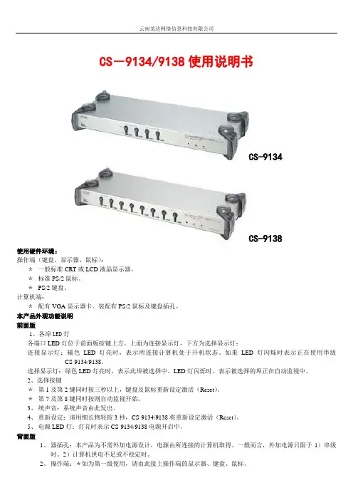
CS-9134/9138使用说明书CS-9134CS-9138使用硬件环境:操作端(键盘、显示器、鼠标):*一般标准CRT或LCD液晶显示器。
*标准PS/2鼠标。
*PS/2键盘。
计算机端:*配有VGA显示器卡。
装配有PS/2鼠标及键盘插孔。
本产品外观功能说明前面版1、各埠LED灯各端口LED灯位于前面版按键上方。
上面为连接显示灯,下方为选择显示灯:连接显示灯:橘色LED灯亮时,表示所连接计算机处于开机状态。
如果LED灯闪烁时表示正在使用串级CS-9134/9138。
选择显示灯:绿色LED灯亮时,表示此埠被选择中。
LED灯闪烁时,表示被选择的埠正在自动监视中。
2、选择按键*第1及第2键同时按三秒以上,键盘及鼠标重新设定激活(Reset)。
*第7及第8键同时按则自动监视开始。
3、统声音:系统声音由此发出。
4、重新设定:请用细长物轻按3秒,CS-9134/9138将重新设定激活(Reset)。
5、电源LED灯:灯亮时表示CS-9134/9138电源开启中。
背面版1、器插孔:本产品为不需外加电源设计。
电源由所连接的计算机取得。
一般而言,外加电源只限于1)串级时。
2)计算机供电不足或不稳定时。
2、操作端:*如为第一级使用,请由此接上操作端的显示器、键盘、鼠标。
*如为串级使用,请连接到上一级的计算机端。
3、计算机端:请由此接上计算机端。
CS-9138连接示意图本产品安装程序注意:为能快速且正确安装,请于安装前确认所有机器是否全部关机。
单机使用时1.请于CS-9134/9138接上操作端的显示器、键盘、鼠标。
2.单机时,请使用本公司的三合一高品质KVM专用线材连接计算机。
3.如要外加电源,请将变压器接上。
(请注意:CS-9134/9138计算机键盘端口取得所需电源,如供电不足,请外加电源供应器)4.请将计算机电源打开。
串级第二级使用时(串一级使用):如将CS-9134/9138计算机端第一端口串级另一台CS-9134/9138,增加3/7台计算机连接使用。
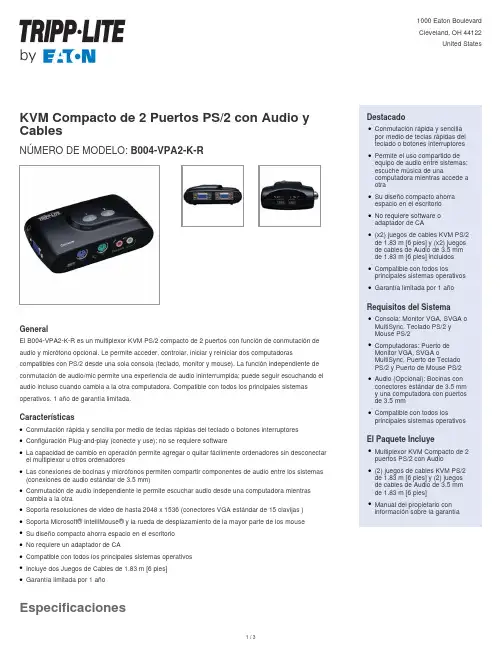
EspecificacionesKVM Compacto de 2 Puertos PS/2 con Audio y CablesNÚMERO DE MODELO:B004-VPA2-K-RGeneralEl B004-VPA2-K-R es un multiplexor KVM PS/2 compacto de 2 puertos con función de conmutación de audio y micrófono opcional. Le permite acceder, controlar, iniciar y reiniciar dos computadorascompatibles con PS/2 desde una sola consola (teclado, monitor y mouse). La función independiente de conmutación de audio/mic permite una experiencia de audio ininterrumpida; puede seguir escuchando el audio incluso cuando cambia a la otra computadora. Compatible con todos los principales sistemas operativos. 1 año de garantía limitada.CaracterísticasConmutación rápida y sencilla por medio de teclas rápidas del teclado o botones interruptores q Configuración Plug-and-play (conecte y use); no se requiere softwareq La capacidad de cambio en operación permite agregar o quitar fácilmente ordenadores sin desconectar el multiplexor u otros ordenadoresqLas conexiones de bocinas y micrófonos permiten compartir componentes de audio entre los sistemas (conexiones de audio estándar de 3.5 mm)qConmutación de audio independiente le permite escuchar audio desde una computadora mientras cambia a la otraqSoporta resoluciones de video de hasta 2048 x 1536 (conectores VGA estándar de 15 clavijas )q Soporta Microsoft® IntelliMouse® y la rueda de desplazamiento de la mayor parte de los mouse q Su diseño compacto ahorra espacio en el escritorio q No requiere un adaptador de CAq Compatible con todos los principales sistemas operativos q Incluye dos Juegos de Cables de 1.83 m [6 pies]q Garantía limitada por 1 añoqDestacadoConmutación rápida y sencilla por medio de teclas rápidas del teclado o botones interruptores qPermite el uso compartido de equipo de audio entre sistemas;escuche música de unacomputadora mientras accede a otraqSu diseño compacto ahorra espacio en el escritorio qNo requiere software o adaptador de CAq(x2) juegos de cables KVM PS/2de 1.83 m [6 pies] y (x2) juegos de cables de Audio de 3.5 mm de 1.83 m [6 pies] incluidos qCompatible con todos losprincipales sistemas operativos qGarantía limitada por 1 añoqRequisitos del SistemaConsola: Monitor VGA, SVGA o MultiSync, Teclado PS/2 y Mouse PS/2qComputadoras: Puerto de Monitor VGA, SVGA oMultiSync, Puerto de Teclado PS/2 y Puerto de Mouse PS/2qAudio (Opcional): Bocinas con conectores estándar de 3.5 mm y una computadora con puertos de 3.5 mmq Compatible con todos losprincipales sistemas operativosqEl Paquete IncluyeMultiplexor KVM Compacto de 2puertos PS/2 con Audio q(2) juegos de cables KVM PS/2de 1.83 m [6 pies] y (2) juegos de cables de Audio de 3.5 mm de 1.83 m [6 pies]qManual del propietario con información sobre la garantíaq1 / 32 / 3Periodo de Garantía del Producto (ANivel Mundial)Garantía limitada por 1 año© 2023 Eaton. All Rights Reserved.Eaton is a registered trademark. All other trademarksare the property of their respective owners.3 / 3。
KVM切换器使用方法KVM切换器使用方法kvm切换器简单说就是用一套键盘鼠标显示器控制多台主机的设备,kvm切换器发展至今相信很多人也对kvm切换器使用方式方法有所了解,下面以迈拓维矩8口kvm切换器为例简单说明kvm切换器的使用方法。
迈拓维矩8口kvm切换器提供2种切换方式:第一.按键切换:该切换方式只要将线缆与工作的主机连接好后,即可在kvm切换器前面板上进行按键切换。
第二.遥控切换:同样的接好线缆,通过配的遥控器按相应数字即可切换到相应主机,方便快捷。
虽然kvm切换器已经普及,kvm切换器的使用方法也被大家熟知,但是kvm切换器在使用过程中还是会碰到很多问题,迈拓维矩为大家整理并附上简单解决方法。
A. 如何关闭kvm切换器切换时的声音一般情况下是热键两下+ 一个特定的字母,如迈拓维矩的的KVM 切换器,就是Scroll Lock 2次+“B”或者Scroll Lock 2次+“F12”实现声音的开关。
B. MT-262KL/462KLKVM切换器切换后提示要求安装驱动在电脑端更新电脑USB驱动即可解决。
C. 2口KVM切换器切换后闪屏怎么办1.调节电脑分辨率和刷新频率2..把显示器线材换产品原配线3.更新电脑显卡驱动;希望可以帮到你D. 迈拓维矩8进1出KVM切换器开机进入系统后没显示怎么办?1. 迈拓维矩8进1出KVM切换器开机进入系统后没显示,关闭BIOS USB开机自动检测功能。
2.显示部分的情况检查EDID是否读取到,可以开好机之后,再接产品,查看是否有显示;3.没显示,有可能是线材或者产品故障,有显示的情况,判定线材是否是3+4规格以上的线材,显卡驱动最新,才可以读取到EDID,才可以显示。
希望可以帮到您。
E. 新买的的KVM切换器不能使用的原因可能你使用过KVM切换器,很多时候可能买回来后连接不能使用,或者出现显示效果不好,有重影、视频失真等状况,可能你第一时间想到的是产品质量,质量是一个原因,但不是唯一的。
4路kvm多电脑切换器操作方法说明迈拓维矩工业级kvm切换器能为你节省空间,金钱,时间,设备和功耗,它能通过一套键盘、鼠标、显示器来控制多台电脑。
Kvm多电脑切换器具有热键切换、桌面式开关、面板按钮和自动扫描等特点。
二、4路/4口kvm多电脑切换器特性1、usb2.0端口,特带usb hub接口支持任何usb2.0设备2、vga信号、音频、usb、可分开使用:如接上电源,只需插入vga输入源无需接usb信号,可以把产品当成4口vga或者音频切换器3、支持dos,win95/98/98se/2000/me/xp.winnt,netware,unix,linux4、即插即用,无需关掉kvm切换器的电脑就可以,插上或者拔掉所连接的电脑,不建议热插拔5、优良的画质:分辨率可达1920*1440带宽:350mhz6、无需软件控制:可通过按钮、键盘热键,osd菜单切换所要操作的电脑主机7、当确定端口切换时会发出蜂鸣声8、指示状态的led指示灯9、支持自动扫描,默认扫描时间为3秒三、4路/4口kvm多电脑切换器连接图示四、4路/4口kvm多电脑切换器热键介绍除面板按钮外,也可通过简单的键盘组合键使用kvm切换器端口,只需要在2秒内连续按下home/caps/scroll/num键2次就可以发送命令给kvm,随后会听到“嘟音”确认可以使用热键命令了,此产品有多个模式可选择。
【home】+【home】是产品默认模式,当您不想用这个模式是可选择别的命令模式,一下是设定不同热键模式Home+home模式(默认模式)Home+home+caps 进入热键caps模式Home+home+scroll 进入热键scroll模式Home+home+num 进入热键num模式默认模式命令Home+home+1.2……切换到对应端口Home+home+→或者↓切换下一端口Home+home+←或者↑切换上一端口Home+home+B 关闭或者打开蜂鸣器声音Home+home+S 自动扫描,按任意键停止扫描,并停留在当前端口【home】+【home】+I+数字+enter 设置自动扫描没端口停留时间,数字为5~999秒。
最后将控制这4台电脑的键盘、鼠标、显示器再接在KVM上,可以打开电脑使用了。
在2台电脑之间切换的时候,只需要按KVM上面的开关就可以了!也可以用热键切换!热键的切换方法如下:1、切换到第一台电脑:Scroll Lock + 1 (第1台电脑)2、切换到第二台电脑:Scroll Lock + 2 (第2台电脑)3、自动扫描电脑模式:Scroll Lock + S4、重置键盘和鼠标:Scroll Lock + end5、切换电脑提示音关闭:Scroll Lock + B6、往上切换电脑:Scroll Lock + ↑(切换到上一台电脑)7、往下切换电脑:Scroll Lock 下+↓(切換到上一台电脑)配套的KVM连接线长1.5米,如果电脑相隔距离比较远,就需要配更长的线。
共享器上有一个电源插座的位置,但KVM是由电脑供电,只有超长距离使用,电压不够的时候才需要使用外接电源,一般短距离不需要外接电源,标准产品中不附带的电源!使用前请注意,电脑启动前,需要通过KVM将键盘、鼠标、显示器切换到待启动电脑上,否则可能会出现启动后找不到鼠标的现象!1、支持MicrosoftIntellimouse, Microsoft IntelliMouse Explorer, Logitech Net Mouse 或MicrosoftMouse 相容機種。
2、支援DOS, Win3.X, Win95/98/98SE/2000/ME/XP, WinNT, Netware,Unix, Linux 无须关闭电脑电源,支持热插拔连接线.3、支持高画质影像输入,最高可达到1920X1440 (頻寬:200MHz )4、不需要安裝软件即可透过按钮或者键盘热键切换。
支持自动扫描模式以上监控所有电脑。
5、切换电脑时可回复各台电脑的键盘状态灯。
提供LED来监视目前各台电脑的使用状况。
切换电脑时会有提示音来确认。
ATEN 新一代KVM over IP 切換器遠端電腦管理系列方案可讓本地控制端與遠端的IT 管理人員透過網路瀏覽器監看與管控整個企業資料中心設備。
此外,該系列方案提供頻外管控功能,包括支援外接數據機–當網路斷線時可以由電話連線執行BIOS 層級的問題排除。
為了讓管理人員能控管整個機房環境,KVM Over IP 切換器遠端電腦管理系列方案也支援刀鋒伺服器與機箱,其包含了幾項新的強大功能,例如電源整合(Power Association)功能,其可連接KVM 多電腦切換器連接埠與ATEN PDU 電源分配器上的電源插座,進而從切換器的介面上管理電源的運作。
KVM Over IP 切換器現在可支援CCVSR(電腦管理畫面側錄解決方案)軟體. CCVSR 安全地記錄下透過KVM Over IP 切換器存取電腦時的操作影像及作業. ,記錄從BIOS 到登入的操作,從軟體應用程式執行到作業系統的任何設定 - 所有動作皆可一一地被側錄並儲存起來,無一例外KVM Over IP 切換器遠端電腦管理系列方案其他強大的功能還包括:訊息板功能、畫面分割模式、滑鼠動態同步顯示與電腦端模組ID。
透過雙網路介面卡,KVM Over IP 切換器遠端電腦管理系列方案可以確保持續的機房與資料中心服務,提供全天候的高可靠度。
雙IP 操作提供完善的備援與高可靠度。
如果其中一個IP 中斷時,另一個IP 即會自動接替,確保系統正常運作。
現在 ,採用KVM Over IP 切換器遠端電腦管理系列方案, IT 管理人員可從任何地方管控管理機房與資料中心設備–大幅降低差旅費用及平均維修時間,確保資料中心服務的持續運作。
KVM Over IP切換器遠端電腦管理系列方案前板背板KN2116A • 16埠• 1位本地端與2位遠端使用者管控 KN2132• 32埠• 1位本地端與2位遠端使用者管控 KN4116• 16埠• 1位本地端與4位遠端使用者管控KN4132• 32埠• 1位本地端與4位遠端使用者管控硬體• 高密度連接埠–32個RJ-45介面的連接埠,僅佔1U機架空間• 兩個或四個遠端存取通道與一個近端控制端• 內建兩組10/100/1000 Mbps網路介面卡可提供區域網路備援或雙IP操作能力•支援刀鋒伺服器New!• 支援PS/2, USB, Sun Legacy (13W3) 及序列(RS-232)連接• 本地控制端支援PS/2及USB鍵盤與滑鼠• 支援跨平台伺服器環境:Windows, Mac, Sun, Linux以及VT100為基礎的序列裝置• 高視訊解析度–伺服器與KVM多電腦切換器之間距離最遠達50公尺時,本地控制端視訊解析度最高可達1600 x 1200 @ 60Hz,32位元色深;遠端視訊解晰度最高可達 1600 x 1200 @ 60Hz,24位元色深• 單一層級可監控多達16或32台伺服器,或透過堆疊串接方式,可管理多達512台伺服器** 可相容堆疊串接的KVM多電腦切換器包括:CS9134, CS9138, CS88A, KH1508, KH1516, KH1508A及KH1516A。
深圳市秦安科技有限公司KVM-1708/1716-P3.0控制平台(8口/16口)用户手册产品描述KVM-1708/1716是一个集成了多端口KVM切换功能于1U高度空间的控制平台,它通过一组设备(包含LCD显示器、键盘、鼠标)实现对多台计算机的操作。
从而节省了为每台计算机单独配置键盘、鼠标、监视器的费用以及它们所占用的空间。
安装快速简单,只需要将电缆连接到正确的端口上,而无须软件配置,因此不存在复杂的安装过程或不兼容问题。
产品特性●17” LCD TFT 液晶显示屏,高亮度,高清晰,高分辨率显示●1U 高度,适应于19”标准机柜安装,金属结构●超薄键盘99键,带数字小键盘,标准PS/2接口●采用触摸板鼠标,高分辨率,高灵敏度。
2个功能按键和滚轮功能(触摸板右边横条区域为滚轮功能区),符合PS/2 标准接口切换器功能●可直接连接8/16台电脑并实现切换操作●警音提示切换完成●无需安装附加软件,通过OSD菜单或热键操作,非常容易地在多台电脑间切换●切换电脑时,会自动记录并存储键盘、鼠标原有的工作状态●在自动扫描(auto-scan)模式下鼠标可正常使用●DDC模拟功能- 每台服务器的视讯设定会自动调整至屏幕显示的最佳状态●只用鼠标即可完成主机间的切换操作●具有热插拔功能(直接增加或移除主机而无需关闭KVM电源)外观图1-1.1整体外观尺寸图前视图(见图1-1.2)图1-1.2 KVM-1708前视图1.液晶显示屏2.后挂耳导槽3.LCD OSD控制键4.键盘5.前挂耳6.触摸鼠标7.拉手8.锁扣9.显示面板后视图(见图1-1.3)图1-1.3 KVM-1708后视图1 PC连接端口: 8个端口(集成VGA/键盘/鼠标信号输入端)2 电源输入插座(AC 或DC)3 电源开关4 接地螺钉5 Console : 外接显示器使用6 Update前视图(见图1-1.4)图1-1.4 KVM-1716 前视图1.液晶显示屏2.后挂耳导槽3.LCD OSD控制键4.键盘5.前挂耳6.触摸鼠标7.拉手8.锁扣9.显示面板后视图(见图1-1.5)图1-1.5 KVM-1716 后视图1 PC连接端口: 16个端口(集成VGA/键盘/鼠标信号输入端)2 电源输入插座(AC or DC)3 电源开关4 接地螺钉5 Console : 外接显示器使用6 Update机架安装KVM-1708/1716控制平台符合标准19”机柜的安装要求,由前向后安装,后挂耳插入导槽内,安装好后,锁紧前后挂耳螺丝。
用户手册CS-14 CS-14CCS-14包装说明如下:- 1 4端口小型KVM 切换器(CS-14或CS-14C)-1用户手册此外,CS-14C包装也包括:2 CS 定做的延长线缆(1.2米)2 CS 定做的延长线缆(1.8米)请仔细阅读此用户手册,并按照说明进行安装及操作,避免对CS-14或其他附件设备造成损坏。
宏正自动科技股份有限公司ATEN PAPE-1143-2000 1999版所有产品名称和商标都已注册,版权所有。
概述Master View CS-14 KVM (键盘、鼠标、显示器)是一种控制设备,可以实现通过一个控制端(键盘、鼠标、显示器)访问4台主机。
在Master View KVM系列产品研制出来之前,从一个控制端控制多台主机的唯一方式是通过连线复杂且造价昂贵的网络系统。
现在,通过使用Master View CS-14, 您就可以方便快捷地实现对4台主机的访问。
Master View CS-14提供了两种对所接系统便捷的访问方式:使用位于前面板上的Selection (选择)按钮;从键盘输入热键组合。
安装简单快捷,只需将对应线缆连接起来即可。
无需安装光盘,因此没有复杂繁琐的安装程序,也无须考虑不兼容的问题。
因为Master View CS-14直接接收键盘输入信息,所以它可以在任何硬件平台上进行操作,也可以与所有操作系统兼容。
Master View CS-14是省时、省钱的最佳选择。
因为CS-14支持通过一个控端台控制两台PC 主机,所以避免了为每台主机配置独立键盘、鼠标、显示器的费用支出,同时节省了工作空间,也避免了不断从一台电脑移动到另一台电脑的麻烦。
功能特性。
支持Microsoft IntelliMouse及多数的滾轮滑鼠。
键盘与鼠标模拟功能-避免计算机出错启动。
进行切换时,将保存之前Caps Lock、Num Lock和Scroll Lock的状态。
支持最高分辨率1920 x 1440。
易于安装——无须软件——只须将线缆插入PC主机端口即可;。
易于操作——可通过按钮或热键进行PC选择。
自动扫描功能监视PC主机操作状况。
与所有操作平台相兼容。
LED指示灯显示便于监视各端口状态。
省时、省空间、省电、省设备购置费用。
无需外接电源。
支持DDC2B(显示数据渠道)。
支持热插拨硬件需求控制端-所接主机须具有最高分辨率的VGA, SVGA或Multisync显示器-一个PS/2鼠标-一个PS/2 类型的键盘或AT类型的鼠标,附带一个键盘转换器PC所接各主机必须符合以下安装:-一张VGA, SVGA 或Multisync卡-一个6-pin mini-DIN (PS/2) 鼠标端口一个6针mini-DIN (PS/2 )键盘端口(4号针上有5伏直流电,3号针为地线)或一个5针AT 类型键盘端口(5号针上有5伏直流电,4号针为地线)**请见下一节中线缆下方的备注。
线缆虽然可以使用标准线缆对PC主机和Master View CS-14进行连接,但是,为了达到最佳信号整合效果及简化线缆连接,我们强烈建议您使用产品包装内所附的高品质KVM专用线缆(部分号码2L-1001P/C)。
备注:键盘和鼠标线缆两端均为PS/2连接头:-如果您的主机是标准的AT键盘插口,要将线缆插入PC键盘端口,则必须使用PS/2-AT 的转换器(单独购买)。
-CS-14只支持PS/2鼠标——不支持串口鼠标。
介绍顶部视图1.已选LED 指示灯指示灯亮显示此端口为当前选定端口。
根据端口具体状态,指示灯将按照一定的对应信息闪烁(详细请见附录表格)。
2.右视图端口选择按住推动按钮通过4个CPU 端口(A→B→D→E→A.etc)选择在线端口。
CPU 控制端连接端口4个CPU 端口分别有三个连接接口,控制端也一样。
每个连接接口都有相应的标识。
1.视频连接口2.PS/2 类型的键盘连接接口3.PS/2 类型的鼠标连接接口安装安装前,请关闭即将连接的所有设备的电源。
1、将键盘、鼠标和显示器分别插入Master View CS-14的控制端端口。
2、使用线缆(请见硬件要求中的描述) 分别将主机的键盘、鼠标和显示器端口与MasterView CS-14的CPU端口连接起来,请参见以下连接示意图:备注:如果您的PC主机键盘使用AT连接头,请参见p.3线缆中备注说明。
3、开启所接PC主机电源。
备注:CS-14的Power On预设值是连接A 端口。
如果端口A连接的计算机处于未活动状态,显示器则会处于黑屏的状态。
现在却不会出现这种状况,因为可以通过端口选择的方式切换到其它的端口处于活动状态的计算机(B,D 或E)操作Master View CS-14是实现从一个控制端控制两台主机的最便捷的方式。
可使用两个端口的选择方式,对任一端口进行快速的访问。
-端口手动选择-端口热键选择端口手动选择使用端口手动选择方式,只需要按Master View CS-14右面板上的端口选择按钮在主机间来回切换选择。
面板上方指示灯亮显示所对应端口为当前操作端口。
端口热键选择热键方式允许从键盘上直接选择当前操作主机,而无须按端口选择按钮进行手动选择。
Master View CS-14提供以下几种热键选择功能特性:-选择当前操作端口-自动扫描模式-上/下模式备注:按住和释放Alt+Ctrl+Shift 组合键开始所以得热键操作。
组合必须在同一边LeftAlt+LeftCtrl+LeftShift 或者RightAlt+RightCtrl+RightShift选择当前操作端口:每个CPU 端口都被分配一个按字母顺序的ID(CPUA,CPUB,CPUD,CPUE)每个端口。
一个端口ID 号码可以和每个字母相对应。
您可以通过确认端口ID 作为热键组合的一部份可访问所连接的计算机。
1.按住和释放Alt+Ctrl+Shift2.输入相应的端口ID 号码(1.2.3.或4)3.按住[Enter]端口ID 号码与端口字母相对应。
端口字母端口ID 号码A 1D 3E 4。
式模描扫动自出退先 键格 空 按须必作操的端制控对复恢要果如。
作操常正法无盘键,时作操描扫动自行进在:注备 。
口端作操前当为 持保将口端作操的时止停描扫。
式模描扫动自出退 键格空 按到直,续持直一将后始开描扫1. 2. 3. ] Alt+Ctrl+Shift 0 [Enter] [ ] [住按 放释 住按 , 放释 住按 。
合组键热 的下以入输可,式模描扫动自动启要。
况状行运的机主有所视监以可就换切动手己自须无您 ,此因,描扫换切动自行进机主对隔间间时的定一以将能功描扫动自的 :式模描扫动自Master View CS-14。
式模下 上出退先 键格空 按须必作 操的端制控对复恢要果如。
作操常正法无盘键,时态状的效有于处式模式模下 上当:注备 。
机算计台一下到换切可键 的边右住按。
机算计台一上到换切机主前当从可,键 的边左住按,式模下 上于处旦一 住按 放释和住按 , 放释和住按 :合组键热下以入输。
式模下向 上向动启。
反相好正换切隔间间时的定固 个一在式模描扫动自与。
口端的别特个一在留停意随可,短或长的间时管不您让可法方种这 。
式模描扫动自用使替代。
们它控监动手以换切后向和前向间之机算计在您许允式模下 上 式模下 上Shift 1. 2. 3. / / [Enter] [ / / Alt+Ctrl+Shift 9 ] / Shift /米毫 )高 宽 长(寸尺 克 量重 料塑 壳外 , 度湿 ℃ ℃ 度温存储 ℃0 ℃5 度温作操 口端 ) 准标(头公 端制控 ) 准标(头母 器示显 口端 )型 (头母 端制控 )型 (头母 标鼠 口端 )型 (头母 端制控 )型 (头母 盘键 头接连 择选 灯示指 键热;钮按换切 择选口端 量数接连 格规细详LED PC x x 250 -20 4 4 0 ~ 80%RH Non condensing 1 x HDB-15 4 x HDB-15 170 x 87x 28.5 ~4 ~ 60 1 x 6 pin mini-DIN 4 x 6 pin mini-DIN 1 x 6 pin mini-DIN 4x 6 pin mini-DIN VGA/SVGA VGA/SVGA - CPU PS/2 PS/2 PS/2 PS/2 - CPU - CPU /。
问访所式模下 上被正且口端作操当为机主接所口端此 )暗间时短,亮间时长(烁闪 。
问访所式模描扫动自被正且口端作操当为机主接所口端此 )替交亮暗(烁闪 。
口端作操当为机主接所口端此 )定稳(亮 。
口端此择选未 闭关 息信应对 态状灯示指 :息信应对态状示显灯示指 录附LED。
题问示显幕屏的能可除 好 消可缆线质品高用使。
缆线用专质品高的附所装包用使您议建烈强 够不量质缆线 。
为宽带大最。
率辨分高最的 高太置设宽 , 面界( 及 ) 、 、 持支 带或 和率辨分 能 功轮滚的标鼠数多大持支也,持支供提征特加附有所的标鼠软微对 只备设个这,准标的类种多很有器动驱标鼠, 标鼠的子轮和钮按的 ) 外额有( 说来标鼠的列系代现对为因)供提统系作操是或,得获那 , 动驱 商造制从可(器动驱的确正装安标鼠为认确以器理管备设的你查检 标鼠的确正不 。
式模 为置设标鼠定确请。
标鼠口 式模口 串持支不 。
式模口串或 为置设以可标鼠些有 串成置设标鼠 置重要 。
机主启开新重,钟秒五待等,机主闭关 需 。
去回插再后然,出拔中口插标鼠端制控从标鼠将 置重要需标鼠 。
的用使能不 是器换转的口端标鼠口串有带。
口端标鼠的型类 有装须必机算 计此因。
号信此换转能不器换转 。
的同不是号信标鼠口串和号信标 用使的器 鼠 。
作工下机算计的口端标鼠型类 和标鼠 在备设此 换转口端标鼠 上座插在插固牢们它保确,接连缆线的有所对核 懈松缆线 式 模下 上或式模 描扫动自于处 式模下 上 描扫动自出退键格空住按 确正不 后然,码号 口端后然 后然 ,键个每放释和住按独单,令命键热入输新重 入输序顺键热 机算计的 口端的接连机算计的启开已择选令命入输新重 源电闭关已接 口端换更动手钮按换切择选的应相住按过通 连口端的择选 式 模下 上或式模 描扫动自于处 。
式模下 上或式模描扫动自出退 键格空 按 正 开打后然 置重要 , 开打,钟秒五待等, , 和机主闭关 需 。
去回插再后然,出拔中口插盘键端制控从盘键将 置重要需盘键 上座插在插固牢们它保确,接连缆线的有所对核 懈松缆线 法办决解 因原Master View Master View Master Master View / / / View Master View CS-14 1280x1024Hz [ ID PS/2 ] Master View CS-14 PC PS/2 PS/2 PS/2 VGA / / [Enter] PS/2 SVGA Multisync 150MHz / [Ctrl] Master View CS-14 XGA Master View [Shift][Alt] PS/2题问 示显 幕屏应 反无 标鼠应反 键热 住按应 反无 盘键 障故。