68C468--防错
- 格式:ppt
- 大小:1.42 MB
- 文档页数:86

IBM System Storage SAN Volume ControllerIBM Storwize V7000Information Center ErrataVersion 6.3.0April 27, 20121Contents Introduction (4)Who should use this guide (4)Last Update (4)Change History (4)iSCSI Limits (5)iSCSI Limits with Multiple I/O Groups (5)Definition of terms (5)Limits that take effect when using iSCSI (6)Single I/O Group Configurations (6)iSCSI host connectivity only (6)Mixed iSCSI and Fibre Channel host connectivity (6)Multiple I/O Group Config (7)Symptoms of exceeding the limits (7)Configuring the HP 3PAR F-Class and T-Class Storage Systems (8)Minimum Supported STORWIZE V7000 Version (8)Configuring the HP 3PAR Storage System (8)Supported models of HP 3PAR Storage Systems (8)Support firmware levels of HP 3PAR storage arrays (8)Concurrent maintenance on HP 3PAR storage arrays (8)HP 3PAR user interfaces (8)HP 3PAR Management Console (9)HP 3PAR Command Line Interface (CLI) (9)Logical units and target ports on HP 3PAR storage arrays (9)LUNs (9)LUN IDs (9)LUN creation and deletion (10)LUN Presentation (10)Special LUNs (10)LU access model (11)LU grouping (11)LU preferred access port (11)Detecting Ownership (11)Switch zoning limitations for HP 3PAR storage arrays (11)Fabric zoning (11)Target port sharing (11)Controller splitting (12)Configuration settings for HP 3PAR storage array (12)Logical unit options and settings for HP 3PAR storage array (12)Creation of CPG (12)Set up of Ports (13)Setup of Host (14)LUN creation (15)Host options and settings for HP 3PAR storage array (16)2Quorum disks on HP 3PAR storage arrays (16)Clearing SCSI reservations and registrations (17)Copy functions for HP 3PAR storage array (17)Thin Provisioning for HP 3PAR storage array (17)Recommended Settings for Linux Hosts (18)Multipath settings for specific Linux distributions and Releases (19)Udev Rules SCSI Command Timeout Changes (21)Editing the udev rules file (22)3IntroductionThis guide provides errata information that pertains to release 6.3.0 of the IBM System Storage SAN Volume Controller Information Center and the IBM Storwize V7000 Information Center.Who should use this guideThis errata should be used by anyone using iSCSI as a method to connect hosts, Connecting Linux hosts using Fibre Channel or when connecting HP 3PAR Storage to IBM System Storage SAN Volume Controller or IBM Storwize V7000 .Last UpdateThis document was last updated: April 27, 2012.Change HistoryThe following revisions have been made to this document:Revision Date Sections ModifiedNov 18, 2011 New publicationApr 27 2012 Linux Host SettingsTable 1: Change History4iSCSI LimitsiSCSI Limits with Multiple I/O GroupsThe information is in addition to, and a simplification of, the information provided in the Session Limits pages at the following links:/infocenter/StorwizeV7000/ic/index.jsp?topic=/com.ibm.storage.Storwize V7000.console.doc/StorwizeV7000_iscsisessionlimits.html/infocenter/storwize/ic/topic/com.ibm.storwize.v7000.doc/S torwize V7000_iscsisessionlimits.htmlDefinition of termsFor the purposes of this document the following definitions are used:IQN:an iSCSI qualified name – each iSCSI target or initiator has an IQN. The IQN should be unique within the network. Recommended values are of the formiqn.<date>.<reverse domain name>:<hostname>.<unique id> e.g. iqn.03-.ibm.hursley:host1.1initiator: an IQN that is used by a host to connect to an iSCSI targettarget: an IQN on an STORWIZE V7000 or V7000 node that is the target for an iSCSI logintarget portal: an IP address that can be used to access a target IQN. This can be either an IPv4 or an IPv6 address.5Limits that take effect when using iSCSISingle I/O Group ConfigurationsiSCSI host connectivity only1 target IQN per node2 iSCSI target portals (1xIPv4 and 1xIPv6) per network interface on a node4 sessions per initiator for each target IQN256 defined iSCSI host object IQNs512 host iSCSI sessions per I/O group **256 host iSCSI sessions per node (this is to allow the hosts to reconnect in the event of a failover)** e.g. if a single initiator logs in 3 times to a single target count this as 3. If a singleinitiator logs in to 2 targets via 3 target portals each count this as 6.Only the 256 defined iSCSI IQN limit is enforced by the GUI or CLI commands. Mixed iSCSI and Fibre Channel host connectivity512 total sessions per I/O group where:1 defined FC host object port (WWPN) = 1 session1 defined iSCSI host object IQN = 1 session1 additional iSCSI session to a target = 1 sessionIf the total number of defined FC ports & iSCSI sessions in an I/O group exceeds 512, some of the hosts may not be able to reconnect to the STORWIZE V7000/V7000 targets in the event of a node IP failover. See above section for help on calculating the number of iSCSI sessions.6Multiple I/O Group ConfigIf a host object is defined in more than one I/O group then each of its host object port definitions is counted against the session limits for every I/O group it is a member of. This is true for both FC and iSCSI host objects. By default a host object created using the graphical user interface is created in all available I/O groups.Symptoms of exceeding the limits.The following list is not comprehensive. It is given to illustrate some of the common symptoms seen if the limits defined above are exceeded.. These symptoms could also indicate other types of problem with the iSCSI network.•The host reports a time out during the iSCSI login process•The host reports a time out when reconnecting to the target after a STORWIZE V7000/V7000 node IP failover has occurred.In both of the above cases no errors will be logged by the STORWIZE V7000/V7000 system.7Configuring the HP 3PAR F-Class and T-Class Storage SystemsMinimum Supported STORWIZE V7000 Version6.2.0.4Configuring the HP 3PAR Storage SystemThis portion of the document covers the necessary configuration for using an HP 3PAR Storage System with an IBM Storwize V7000 cluster.Supported models of HP 3PAR Storage SystemsThe HP 3PAR F-Class (Models 200 and 400) the HP 3PAR T-Class (Models 400 and 800) are supported for use with the IBM STORWIZE V7000. These systems will be referred to as HP 3PAR storage arrays. For the latest supported models please visit /support/docview.wss?uid=ssg1S1003907Support firmware levels of HP 3PAR storage arraysFirmware revision HP InForm Operating System 2.3.1 (MU4 or later maintenance level) is the supported level of firmware for use with IBM STORWIZE V7000. For support on later versions, consult /support/docview.wss?uid=ssg1S1003907 Concurrent maintenance on HP 3PAR storage arraysConcurrent Firmware upgrades (“online upgrades”) are supported as per HP procedures. HP 3PAR user interfacesUsers may configure an HP 3PAR storage array with the 3PAR Management Console or HP 3PAR Command Line Interface (CLI).8HP 3PAR Management ConsoleThe management console accesses the array via the IP address of the HP 3PAR storage array. All configuration and monitoring steps are intuitively available through this interface.HP 3PAR Command Line Interface (CLI)The CLI may be installed locally on a Windows or Linux host. The CLI is also available through SSH.Logical units and target ports on HP 3PAR storage arraysFor clarification, partitions in the HP 3PAR storage array are exported as Virtual Volumes with a Virtual Logical Unit Number (VLUN) either manually or automatically assigned to the partition.LUNsHP 3PAR storage arrays have highly developed thin provisioning capabilities. The HP 3PAR storage array has a maximum Virtual Volume size of 16TB. A partition Virtual Volume is referenced by the ID of the VLUN.HP 3PAR storage arrays can export up to 4096 LUNs to the STORWIZE V7000 Controller (STORWIZE V7000’s maximum limit). The largest Logical Unit size supported by STORWIZE V7000 under PTF 6.2.0.4 is 2TB, STORWIZE V7000 will not display or exceeded this capacity.LUN IDsHP 3PAR storage arrays will identify exported Logical Units throughSCSI Identification Descriptor type 3.The 64-bit IEEE Registered Identifier (NAA=5) for the Logical Unit is in the form;5-OUI-VSID .The 3PAR IEEE Company ID of 0020ACh, the rest is a vendor specific ID.9Example 50002AC000020C3A.LUN creation and deletionVirtual Volumes (VVs) and their corresponding Logical Units (VLUNs) are created, modified, or deleted through the provisioning option in the Management Console or through the CLI commands. VVs are formatted to all zeros upon creation.To create a VLUN, highlight the Provisioning Menu and select the Create Virtual Volume option. To modify, resize, or destroy a VLUN, select the appropriate Virtual Volume from the window, right click when the specific VLUN is highlighted.*** Note: Delete the mdisk on the STORWIZE V7000 Cluster before deleting the LUN on the HP 3PAR storage array.LUN PresentationVLUNs are exported through the HP 3PAR storage array’s available FC ports by the export options on Virtual Volumes. The Ports are designated at setup and configured separately as either Host or Target (Storage connection). Ports being identified by a node : slot : port representation.There are no constraints on which ports or hosts a logical unit may be addressable.To apply Export to a logical unit, highlight the specific Virtual Volume associated with the Logical Unit in the GUI and right click and select Export.Special LUNsThere are no special considerations to a Logical Unit numbering. LUN 0 may be exported where necessary.Target PortsA HP 3PAR storage array may contain dual and/or quad ported FC cards. Each WWPN is identified with the pattern 2N:SP:00:20:AC:MM:MM:MM where N is the node, S is the slot and P is the port number on the controller and N is the controller’s address. The MMMMMM represents the systems serial number.Port 2 in slot 1 of controller 0 would have the WWPN of 20:12:00:02:AC:00:0C:3A The last 4 digits of serial number 1303130 in hex (3130=0x0C3A).This system has a WWNN for all ports of 2F:F7:00:02:AC:00:0C:3A.10LU access modelAll controllers are Active/Active. In all conditions, it is recommended to multipath across FC controller cards to avoid an outage from controller failure. All HP 3PAR controllers are equal in priority so there is no benefit to using an exclusive set for a specific LU.LU groupingLU grouping does not apply to HP 3PAR storage arrays.LU preferred access portThere are no preferred access ports on the HP 3PAR storage arrays as all ports are Active/Active across all controllers.Detecting OwnershipDetecting Ownership does not apply to HP 3PAR storage arrays.Switch zoning limitations for HP 3PAR storage arraysThere are no zoning limitations for HP 3PAR storage arrays.Fabric zoningWhen zoning an HP 3PAR storage array to the STORWIZE V7000 backend ports, be sure there are multiple zones or multiple HP 3PAR storage array and STORWIZE V7000 ports per zone to enable multipathing.Target port sharingThe HP 3PAR storage array may support LUN masking to enable multiple servers to access separate LUNs through a common controller port. There are no issues with mixing workloads or server types in this setup.Host splitting11There are no issues with host splitting on an HP 3PAR storage array.Controller splittingHP 3PAR storage array LUNs that are mapped to the Storwize V7000 cluster cannot be mapped to other hosts. LUNs that are not presented to STORWIZE V7000 may be mapped to other hosts.Configuration settings for HP 3PAR storage arrayThe management console enables the intuitive setup of the HP 3PAR storage array LUNs and export to the Storwize V7000 cluster.Logical unit options and settings for HP 3PAR storage array From the HP 3PAR storage array Management Console the following dialog of options are involved in setting up of Logical Units.Creation of CPGThe set up of Common Provisioning Groups (CPGs). If Tiering is to be utilised, it should be noted it is not good practice to mix different performance LUNs in the same STORWIZE V7000 mdiskgrp.Action->Provisioning->Create CPG (Common Actions)12Set up of PortsShown is on a completed 8 node STORWIZE V7000 cluster.Each designated Host ports should be set to Mode; point.Connection Mode: HostConnection Type: PointSystem->Configure FC Port (Common Actions)13Setup of HostHost Persona should be: 6 – Generic Legacy.All STORWIZE V7000 ports need to be included. Actions->Hosts->Create Host (Common Actions)14LUN creationSize limitations: 256 MiB minimum2TB maximum (STORWIZE V7000 limit)Provisioning: Fully Provision from CPGThinly ProvisionedCPG: Choose provisioning group for new LUN, usually R1,R5,R6 or drive specific. Allocation Warning: Level at which warning is given, optional [%]Allocation Limit: Level at which TP allocation is stopped, optional [%] Grouping: For creating multiple sequential LUNs in a set [integer values, 1-999] Actions->Provisioning->Create Virtual Volumes (Common Actions)15Exporting LUNs to STORWIZE V7000Host selection: choose host definition created for STORWIZE V7000Actions->Provisioning->Virtual Volumes->Unexported (Select VV and right click)Host options and settings for HP 3PAR storage arrayThe host options required to present the HP 3PAR storage array to Storwize V7000 clusters is, “6 legacy controller”.Quorum disks on HP 3PAR storage arraysThe Storwize V7000 cluster selects disks that are presented by the HP 3PAR storage array as quorum disks. To maintain availability with the cluster, ideally each quorum disk should reside on a separate disk subsystem.16Clearing SCSI reservations and registrationsYou must not use the HP 3PAR storage array to clear SCSI reservations and registrations on volumes that are managed by Storwize V7000. The option is not available on the GUI.Note; the following CLI command should only be used under qualified supervision,“setvv –clrsv”.Copy functions for HP 3PAR storage arrayThe HP 3PARs copy/replicate/snapshot features are not supported under STORWIZEV7000.Thin Provisioning for HP 3PAR storage arrayThe HP 3PAR storage array provides extensive thin provisioning features. The use of these thin provisioned LUNs is supported by STORWIZE V7000.The user should take notice of any warning limits from the Array system, to maintain the integrity of the STORWIZE V7000 mdisks and mdiskgrps. An mdisk will go offline and take its mdiskgroup offline if the ultimate limits are exceeded. Restoration will involve provisioning the 3PAR Array LUN, then including the mdisk and restoring any slandered paths.17Recommended Settings for Linux HostsThe following details the recommended multipath ( DMMP ) settings and udev rules for the attachment of Linux hosts to SAN Volume Controller and Storwize V7000. The settings are recommended to ensure path recovery in failover scenarios and are valid for x-series, all Intel/AMD based servers and Power platforms.A host reboot is required after completing the following two stepsEditing the multipath settings in etc/multipath.confEditing the udev rules for SCSI command timeoutFor each Linux distribution and releases within a distribution please reference the default settings under [/usr/share/doc/device-mapper-multipath.*] for Red Hat and[/usr/share/doc/packages/multipath-tools] for Novell SuSE. Ensure that the entries added to multipath.conf match the format and syntax for the required Linux distribution. Only use the multipath.conf from your related distribution and release. Do not copy the multipath.conf file from one distribution or release to another.Note for some OS levels the "polling_interval" needs to be located under defaults instead of under device settings.If "polling_interval" is present in the device section, comment out "polling_interval" using a # keyExamplesUnder Device Section# polling_interval 30,Under Defaults Sectiondefaults {user_friendly_names yespolling_interval 30}18Multipath settings for specific Linux distributions and ReleasesEdit /etc/multipath.conf with the following parameters and confirm the changes using “multipathd -k"show config".RHEL61device {vendor "IBM"product "2145"path_grouping_policy group_by_priogetuid_callout "/lib/udev/scsi_id --whitelisted --device=/dev/%n"features "1 queue_if_no_path"prio aluapath_checker turfailback immediateno_path_retry "5"rr_min_io 1# polling_interval 30dev_loss_tmo 120}RHEL56device {vendor "IBM"product "2145"path_grouping_policy group_by_prioprio_callout "/sbin/mpath_prio_alua /dev/%n"path_checker turfailback immediateno_path_retry 5rr_min_io 1# polling_interval 30dev_loss_tmo 120}19RHEL57device {vendor "IBM"product "2145"path_grouping_policy group_by_prioprio_callout "/sbin/mpath_prio_alua /dev/%n" path_checker turfailback immediateno_path_retry 5rr_min_io 1dev_loss_tmo 120}SLES10SP4device {vendor "IBM"product "2145"path_grouping_policy "group_by_prio"features "1 queue_if_no_path"path_checker "tur"prio "alua"failback "immediate"no_path_retry "5"rr_min_io "1"# polling_interval 30dev_loss_tmo 120}SLES11SP1device {vendor "IBM"product "2145"path_grouping_policy group_by_prioprio aluafeatures "0"no_path_retry 5path_checker turrr_min_io 1failback immediate# polling_interval 30dev_loss_tmo 12020}SLES11SP2device {vendor "IBM"product "2145"path_grouping_policy "group_by_prio"prio "alua"path_checker "tur"failback "immediate"no_path_retry "5"rr_min_io 1dev_loss_tmo 120}Udev Rules SCSI Command Timeout ChangesSet the udev rules for SCSI command timeoutSet SCSI command timeout to 120sOS Level Default Required SettingRHEL61 30 120RHEL62 30 120RHEL56 60 120RHEL57 60 120SLES10SP4 60 120SLES11SP1 60 120SLES11SP2 30 12021Creating a udev rules fileCreate the following udev rule that increases the SCSI command timeout for SVC and V7000 block devicesudev rules filecat /etc/udev/rules.d/99-ibm-2145.rules# Set SCSI command timeout to 120s (default == 30 or 60) for IBM 2145 devices SUBSYSTEM=="block", ACTION=="add", ENV{ID_VENDOR}=="IBM",ENV{ID_MODEL}=="2145", RUN+="/bin/sh -c 'echo 120 >/sys/block/%k/device/timeout'"Reconfirm the settings following the system reboot.22。


美能达复印机代码大全美能达DI181代码1功能模式菜单2技术维修选择3改变固定缩放比率4PM计数器5纸张计数器6卡纸计数器7清除故障代码计数器8消耗品计数器9输入纸张尺寸10ROM版本11应用计数器12区域设置13服务电话0显示测试功能模式:1F1:走纸测试F2:感光鼓/转印电极测试工厂F4:离电极测试工厂F7:原稿尺寸感应器F8:ATDC感应器F12:样本0:中间色1:单点黑线技术维修选择代码默认值4:保养召唤0:取消1:设定7:消耗品80K停机0:可复印1:禁止复印15:缺粉停机0:可复印1:禁止复印20:前边缘消除宽度3:3mm 2~5:2~5mm21:后边缘消除宽度3:3mm 2~5:2~5mm23:同步轴前纸张环线长度100:0 97~104:4.9 -9.8mm31/37/38:ADF停止位置100:0 97~104:4.9 -9.8mm90:选择ATDC的T/C比率100:5%98~103:4.0%-7.0%91:选择Vg输出电压0:低1:高鼓老化后可增加图像浓度PM计数器按纸张选择键,依次改变显示以下内容1:保养计数(递减)2:手动送纸3:第一纸盒4:第二纸盒5:第三纸盒6:第四纸盒7:ADF设定PM计数器:显示PM计数器设定,按清除键清除→输入需要的计数→按开始键保存纸张计数器:显示不同尺寸的计数,按纸张选择键依次改变显示内容。
可以按清除键清除计数:A3→A4→A5→B4→B5→Legal→信纸→11”*17” →11”*14”→发票→FLS卡纸计数器:同上手送→一纸盒→二纸盒→三纸盒→四纸盒→垂直传送→水平传送→出口→ADF送纸→ADF传送→ADF出口→ADF单张手送故障代码计数器:同上消耗品计数器同上IU → 鼓→ 载体→ 刮板→ 定影当IU,显影剂,刮板或定影达到设定值时主机显示M2 当鼓计数达到80K 时,显示M4设定电话:*:空格#:-美能达DI181代码作者:一只游虾2004-12-12 22:29:00)美能达DI181代码美能达DI181代码1功能模式菜单2技术维修选择3改变固定缩放比率4PM计数器5纸张计数器6卡纸计数器7清除故障代码计数器8消耗品计数器9输入纸张尺寸10ROM版本11应用计数器12区域设置13服务电话0显示测试功能模式:1F1:走纸测试F2:感光鼓/转印电极测试工厂F4:离电极测试工厂F7:原稿尺寸感应器F8:ATDC感应器F12:样本0:中间色1:单点黑线技术维修选择代码默认值4:保养召唤0:取消1:设定7:消耗品80K停机0:可复印1:禁止复印15:缺粉停机0:可复印1:禁止复印20:前边缘消除宽度3:3mm 2~5:2~5mm21:后边缘消除宽度3:3mm 2~5:2~5mm23:同步轴前纸张环线长度100:0 97~104:4.9 -9.8mm31/37/38:ADF停止位置100:0 97~104:4.9 -9.8mm90:选择ATDC的T/C比率100:5%98~103:4.0%-7.0%91:选择Vg输出电压0:低1:高鼓老化后可增加图像浓度PM计数器按纸张选择键,依次改变显示以下内容1:保养计数(递减)2:手动送纸3:第一纸盒4:第二纸盒5:第三纸盒6:第四纸盒7:ADF设定PM计数器:显示PM计数器设定,按清除键清除→输入需要的计数→按开始键保存纸张计数器:显示不同尺寸的计数,按纸张选择键依次改变显示内容。

错误排除参孝手册北京发格自动化设备有限公司目录编程错误 (3)准备功能和执行错误 (37)硬件错误 (56)PLC错误 (59)伺服错误 (60)表格数据错误 (65)MC工作模式 (68)编程错误表0001“Linea Vacia”检测时间:在CNC上进行编辑或执行通过DNC传输的程序时。
引起原因:引起这种错误的原因可能是:1当试图进入程序或执行一段空程序段或包含有标号(程序段号)时。
2在《带岛屿的不规则型腔因定循环(G66)》内,当参数“(轮廓的开始)大于参数“E”(轮廓的结束)时。
解决方案:每种情况的解决方案为:1 CNC不能进入程序或执行空程序段。
要进入程序中的空程序段,在该程序段的开始使用符号《;》。
CNC将忽略该程序段的其余部份。
2参数“S”的数值(开始定义轮廓的程序段)必须小于参数“E”的数值(轮廓定义的结束的程序段)。
0002“不合适的数据”检测时间:在CNC上进行编辑或在执行通过DNC传输的程序时。
引起原因:引起这种错误的原因可能是:1当切削条件(F、S、T或D)或M功能后台编辑轴座标时。
2当程序段跳转标志(条件段/1,/2或/3)。
3当用ISO代码格式编程时,编写的程序段号大于是9999时。
4当试图在《不规则型腔》操作的精加工(G68)中定义加工起点的座标时。
5在用高级语言编程时,RPT指令的数值大于9999。
解决方案:每种情况的解决方案为:1记住编程的顺序。
2记住编程的顺序:- 程序跳转(条件程序段/1、/2或/3)。
- 标号(N)。
-《G》功能。
- 轴座标(X、Y、Z……)。
- 加工条件(F、S、T、D)。
-《M》功能。
3更正程序段的语法错误。
程序段的标号应在0到9999之间。
在定义《不规则型腔》操作的精加工循环(G68)时,不能骗写点座标,CNC选择加工的开始点。
编程的格式为:G68B…L…Q…I…R…K…V…然后是切削条件。
1更正程序段的语法错误。
程序中的重复次数应在0到9999之间。
蓝格尔MICRO-468 检测仪简易操作说明
一、电池测试
1、将测试仪红黑夹子夹到被测电池上,红正黑负,测试仪显示屏会显示开机界面。
被测电池电压低于6.0V以下则无法正常测试;按OK键往下继续。
2、按照测试仪提示,依次选择:
●测试状态选择:指电池是否与车内负载连接,有连接则为车内,无连接
则为车外。
●充电状态选择:指电池是否刚充完电,是则为充电后;否则为充电前。
●电池类型选择:指电池的类型,一般选择“普通电池”即可。
如车内测试,还需选择电池极柱方位,一般选择“正装电池”即可。
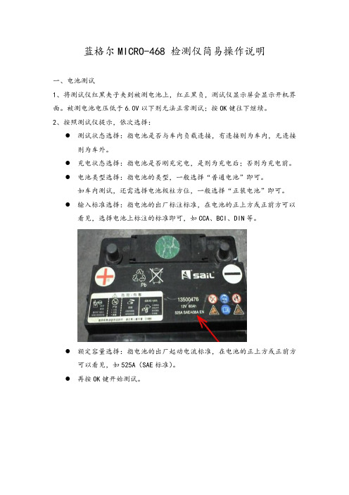
●输入标准选择:指电池的出厂标注标准,在电池的正上方或正前方可以
看见,选择电池上标注的标准即可,如CCA、BCI、DIN等。
●额定容量选择:指电池的出厂起动电流标准,在电池的正上方或正前方
可以看见,如525A(SAE标准)。
●再按OK键开始测试。
测试结果解释:
在夹上测试仪红黑夹子后,测试仪显示开机界面。
在此时按中间“MENU ”键,则进入附加功能菜单。
1、
语言选择:可以选择不同语言;有简体/繁体中文、日语、英语、俄语。
2、 电压表设置:
当电压表选择“开”时,夹上夹子后的开机界面,最下行显示为电压表功能,显示测试夹实时电压值。
当电压表选择“关”时,夹上夹子后的开机界面,最下行没有电压显示值,约2秒后自动进入电池测试程序。
在这2秒内如按“MENU ”键,则进入附加功能菜单。
3、 显示屏背光调节:可以调节显示屏背光亮度。

正常开机状态下按下:C+8键显示错误代码!东芝166出现错误代码C44怎么处理:你的机器是定影器上的热保险有问题。
不过你首先把它清零,看是否好了。
方法:同时按下“0”和“8”开机,当“Ad"字样不在闪烁的时候,输入“400”按下“开始”把"9"改变成“0”按“插入键/中断键”关机再开机就好了。
如果不好你看一下热保险,它已经处于开路状态。
东芝166提示缺粉:东芝166/206复印机原装墨粉检测功能的设置1、08-695代码解释08-695下有二个选项,分别为:0:关闭原装墨粉测试功能(即关闭CTIF对CTRG的检测),此时08-971的值自动设置为3;1:开启原装墨粉测试功能(即开启CTIF对CTRG的检测),此时08-971的值自动设置为1;2、08-971代码解释08-971下有四个选项,分别为:0;墨粉盒空检测,开始检测时墨粉剩余量较多;1:墨粉盒空检测,开始检测墨粉剩余量适中;2:墨粉盒空检测,开始检测墨粉剩余量较少;3:关闭墨粉盒空检测(当08-695设置为0的时候,08-971自动设置为3)注意事项:无论是长江高版本还是低版本,08-695默认设置值为0,08-971默认设置值为3。
纸盒不能设置纸张尺寸了(打印老提示没有安装所需尺寸的纸盒):02开机+地区代码如果是中国就是02+86东芝163出现小扳手怎么办0+8开机→400→开始→0→插入→关机→开机。
出扳手是可以正常工作的,按C键和8键,看看什么代码,没有反映的话,就应该认真的想想你的机子是不是因为别的原因造成的正确步骤:1:按住0+8键不松开机等屏幕出线AD在松手2:输入251 这是屏幕会显示72 (这是因为163是小屏幕同一屏幕只能显示3个数值其实后面还有3个0,你可以按200%这个键就能看到后面3位)3:连着按9个0 然后按插入键4:关机在开小扳手就消失了5:252的值不建议你更改代码:15--照片154%曝光量调整--范围: 0~255, 缺省值=128--------16--照片50%曝光量调整--范围: 0~255, 缺省值=128--------17--照片200%曝光量调整----范围: 0~255, 缺省值=128----C1--主电机锁住C21--光学系统没能完成初始化,光学系统锁住C26--曝光灯烧坏C32--开箱(UA)TD传感器自动调整失败C41--电源接通时,定影热敏电阻异常或者定影灯开路C43--在预热期间,或者在预热完成后定影热敏电阻异常-C44--在预热期间,或者在预热完成后定影灯开路C54--分页器-和主CPU通信错误C55--自动进稿器ADF-和主CPU通信错误C71--ADF主电机锁住C72--由定位传感器检测出的不良调整C73--EEPROM初始化不良C81--分页器输纸电机异常C82--分页器斗移位电机异常------------------------C83--分页器上限错误------------------------C84--分页器下限错误------------------------C85--分页器原位传感器错误------------------------C86--分页器移位传感器错误------------------------C94--在(CH,AJ)模式时,光学系统没能完成初始化,光学系统锁住--------------------E1--机内卡纸------E2--定影附近卡纸------E3--电源ON时有纸保留在复印机内------E4--复印期间前门盖被打开------E5--对位辊附近卡纸------E14--下纸盒进纸卡纸------E71--ADF原稿进稿部分卡纸------E72--ADF原稿传输部分卡纸------E73--ADF原稿排出部分卡纸------E75--ADF 2合1(第2张在原稿传输部分)卡纸------E81--分页器输纸部分复印纸到达时间超过卡纸,纸未到达传感器------E82--分页器输纸部分复印纸等待时间超过卡纸,纸停在传感器------1568的误码表“清除卡纸”或“检修请求”符号一闪一闪时,同时按下:“CLEAR/STOP”和“8”键,会显示以下错误码:1.复印机纸路卡纸错误代码内容备考E01复印机机体内卡纸包括旁送卡纸(旁送LED亮)E02定影器附近卡纸E03打开电源时机内卡纸E05未到达定位开关卡纸在PFU供纸通过传输辊之后还是由PPC供纸之后?2.在供纸部分卡纸错误代码内容备考E14下纸盒卡纸(PFU)纸未到达传输辊3.在ADF传输路径中卡纸错误代码内容备考E71在ADF原稿供纸部分卡纸E72在ADF原稿传输部分卡纸E73在ADF原稿排纸部分卡纸E752合1(第2张原稿在供纸部分卡纸)4。
东芝 168 维修调整代码一:出错代码C01 :主电机锁死C21 :灯架初始化错误C25:扫描单元检测器岀错C26:暴光灯未连接或浪涌检测岀错C38:替换的静电复印单元岀错C41 :电源接通时热敏电阻不正常或加热器未连接C43:定影器断接之后复印机处于预热状态,或待机状态后的热敏电阻不正常C44:定影器断接之后复印机处于预热状态,或待机状态后的加热器不正常C45:在加热器的末端,热敏电阻未连接C56: PFC与主电机之间通信岀错C57:主机与IPC之间通信岀错C71 :供纸马达锁定岀错C73: EE-PROM初始化岀错C74:岀口 /反转岀感器检测到错误的调整C81 :风扇马达锁定岀错C8 2:弓|导传感器调整岀错C95:电源风扇未连接C96:定影风扇未连接C97:真空风扇未连接C98: IC 计时器不能正常工作C99: PFC微机不正常二:调整模式05 项目调整205 :显影器偏压 DC调整初始值 =156 范围 0-255210:栅压初始值调整初始值 =106 范围 0-255220:转印变压器DC输岀高调整初始值 =180 范围 0-255221:转印变压器DC输岀中心调整初始值 =155 范围 0-255222:转印变压器DC输岀低调整初始值 =111 范围 0-255233:分离输岀高调整初始值 =67 范围 0-255234:分离输岀中心调整初始值 =49 范围 0-255235:分离输岀低调整初始值 =35 范围 0-255261 :激光电源 600DPI 初始值调整初始值 =42 范围 0-255304:扫描器输送倍率( 0.1/ 级)初始值 =128 范围 0-255305:扫描器输送不对齐(0.126MM/级)初始值 =128 范围 85-171 306 : CCD 扫描不对齐(0.04233MM/级)初始值 =128 范围 5-251354 : R/ADF 对齐数(表面,0.5MM 级)初始值 =10 范围 0-20355 : R/ADF 对齐数(反面,0.5MM 级)初始值 =10 范围 0-20356 : ADF 位置传感器调整或 RADF 传感器自动调整 357 : R/ADF 传送速度细调(0.1%/级)初始值 =50 范围 0-100358 : R/ADF 水平未对准调整(0.04233MM 级)初始值 =128 范围 0-255365 : R/ADF 顶位置调整(表面, 0.1MM/级)初始值 =50 范围 0-100366 : R/ADF 顶位置调整(反面, 0.1MM/级)初始值 =50 范围 0-100 380 : ADF 容量盘调整,盘窄 381 : ADF 容量盘调整,盘宽 08 项目调整 202 外置计数器选择0 无外置计数器 1 绕组控制器 2 非标准 3 保留 204自动清除 [ 秒 ] 0 无效 1 15 秒 2 30 秒 345 秒 460 秒 575 秒 690 秒 7105秒8 120 秒 9 135 秒 10 150 秒 11 180 秒 12 210 秒 13 240 秒 14 270 秒 15 300秒 205自动低功率 0 无效 1 有效206自动睡眠 0 无效 1 有效 224 : SFB 尺寸0 A3 1 A4 2 A4R 3 A5R 4 B4 5 B5 6 B5R 7 LETTER 8 LETTER-R9 LEDGER 1O LEGAL 11 STATEMENT-R12 COMPUTER 13 FOLIO14 未定义 15 COM10 225 复印机纸盒尺寸0 A3 1 A4 2A4R 3 16 MONARCH A5R 4 B4 5B5 6 B5R 7 LETTER 8 LETTER-R9 LEDGER 1O LEGAL 11 STATEMENT-R 12 COMPUTER 13 FOLIO226 纸盒 2 与 08-225 尺寸一样 227 纸盒 3 与 08-225 尺寸一样 228纸盒 4 与 08-225 尺寸一样250:服务个人电话号码( 20 位)251: PM计数器设置值(0-999999 )252 : PM计数器当前值(0-999999 )255: PFP安装状态0: AUTO(观察PFC纸盒安装状态,自动改到1或2) 1: PFP1 2 : PFP2 3 :保留4 :无256: LCF 尺寸0: A4 1 : LT 2 :保留351 :显示 AR1 模型总计数器数据352:A3/LD 双倍计数0 :单倍计数 1 :双倍计数355:显示 AR1 模型鼓计数器374 : DF扫描计数375:复印作业(打印)计数器376:打印机作业(打印)计数器377:传真作业(打印)计数器385:扫描器单元中总计数器(显示)386:稿台盖扫描计数388 :当替换主PCB扫描单元-复印机时,装载全部计数器指令389:当替换扫描单元复印机 -扫描单元时,装载全部计数器指令 400:热敏电阻加热器状态计数器0:无错误发生1 : C41当启动W-UF时,第一个热敏电阻或加热器岀错2: C41当启动W-UP时,第二个热敏电阻或加热器岀错 3 :保留4: C43在W-UP期间,热敏电阻岀错 5 : C44在W-UP期间,加热器岀错6 : C43待机后,热敏电阻岀错7 : C44待机后,热敏电阻岀错8 : C45待机后,加热器端部热敏电阻岀错9 : C44高温加热器岀错10: C46从待机到开始打印期间加热器或热敏电阻岀错402电源接通小时计数器( 0-999999 )403定影计数器404显影材料计数器406预运行开始时间0 无效 1 30 秒 2 35 秒 3 40 秒 4 45 秒 5 50 秒 6 55 秒 7 60 秒407预运行操作时间0 无效 1 5 秒 2 10 秒 3 15 秒 4 20 秒 5 25 秒6 30 秒7 40 秒8 50 秒9 60 秒 10 150 秒408对厚纸的预运行操作时间0 无效 1 1 秒 2 2秒 3 3秒 4 4秒 5 5秒 6 6秒 7 7秒8 8秒 9 9秒 10 10秒 11 12秒 12 14秒 13 16秒 14 18秒 15 20秒410 打印时的固定温度4 170度5 175度6 180 度7 185度8 190度9 195 度 10 200度 11 205 度12 210 度13 215 度411待机时的固定温度0 170 度 1 175 度 2 180 度 3 185 度 4 190 度 5 195 度 6 200 度7 DROP CONTROL ON412低功率时的固定温度0:OFF 1: 120度 2:130度 3:140度 4:150度 5:160度 413:厚纸张的固定温度0:无效 1:195度 2:200度 3:205度 4:210度462 :切换到RADF昆合文件装载0:无效 1 :有效480:纸盒优先级选择0: A4/LT 1 : LCT 2 :纸盒 1 3 :纸盒 2 4 :纸盒 3 5 :纸盒 4 481:自动纸盒改变0:无 1 :正常483:多棱电机前启动设置0:有效 1:无效 2 :仅为 DF503:在图象质量模式中的密度缺省0: AUTO 1:亮 3 2 : L2 3 : L1 4 :中心 5 :暗 1 6 : D2 7 : D3 8 :节约墨粉 550:图象模式缺省0:标准 1:照片 2 :文本603:自动双倍模式0:无效 1:单倍 /双倍 2:双倍 /双倍604 : APS优先级选择0: APS 1 :AMS 2:无 3 :全图象 611:书本双倍文件选择0 :左手打开 1 :右手打开614 :功能清除LED闪烁0 :无效 1 :有效620 : APS强制开始0 :按一次 1 :保留 2 :无效641 :自动分页模式也在面板上设置0:无效 1 :装订 2 :分页 3 :无效 4 :垂直和水平交替 5 :分页错位 642:分页器模式优先级选择(面板设置)0:NON SORT 1:STAPLE 2:SORT 3:NON SORT4:ALTERNATION 5:SORT OFFSET 6:NON SORT OFFSET 648:全清时整理器 BIN 初始化0 :无效 1 :无效649:杂志分页设置0 :左手打开 1 :右手打开650 :二合一 / 四合一设置0 :水平写 1 :垂直写665 :设置PPC区缺省673:鼓清零430 :鼓PM设定(转载)东芝 168S 数码复印机的部份代码共享东芝168S解鼓-代码.关于东芝数码复印机之代码 --- 》“解鼓” toshiba 新增加部份 08 代码08-340 鼓寿命计数值设定(当 08-689 设为“1”时有效)接受值 0---99999 ;默认值 168S/208S =27000258s=33000注:当 08-355 中的数值(鼓计数显示)达到设置值( 08-340 鼓寿命设置值)的 10 倍时,鼓”将显示在LCD上当 08-340 中鼓寿命设置值为 0,就不会显示“更换鼓”08-673 鼓想关计数器值清零(当 08-689 设为“1”时有效)进行 08-673 的操作后,下列计数值将被清零;08-355 鼓计数显示08-401 鼓寿命计数东芝数码 168 卡纸类错误代码表:纸卡在机身内纸卡在定影单元附近电源接通时,纸张留在机器内(ADF/RADF除外)在 ADU 里卡纸送纸传感器发生超时错误在ADL送纸卡纸在SFB送纸卡纸纸盒 1 送纸卡纸纸盒 2 送纸卡纸纸盒 3 送纸卡纸纸盒 4送纸卡纸( 208、258 系列)来自 2 的纸张不能到达送纸传感器,所以在纸盒 2 送纸过程中,纸张卡在机身内E32~E36 依次类推C25 扫描单元检测出错更换机身输纸卡纸 E01E02E03E08E09送纸系统卡纸 E11E12E13E14E15E16可选纸盒传送卡纸 E31光学系统呼叫维修 C21 灯架初始话错误。
STANDARD C160/C168/C460/C468多层功能的面板设置操作福州张炯1990年3月编制这是以前玩电台的时候做的记录,现重新编排,制作成PDF 文件,希望对使用这些机器的朋友们有所帮助。
Heimao2007.08.01STANDARD C160/C168/C460/C468多层功能的面板设置操作第一层功能第一层均为面板数字或者符号最简单明了的操作。
在频道显示状态下,按压[#CL]键,可将当前频道之频率转为拨号频率。
第一层的其他功能在此省略去。
第二层功能[F]+[X](注意:先按住F键不放,然后再按下述键)键位扩展功能设置功能1P0发射功率调整2DUAL拨号频率与M00频道双重监视开/关3SFT对未存储的频道进行频道数字/频率数字方式选择4STEP调整步级频率5SAVE省电功能开/关6 F.L键盘锁定功能开/关7T.SQ/DM亚音静噪/音调编码方式转换(装有CTN160时)8RPT设置双频方式+/-9REV/HSC在双频方式中反转收发频率0SET/SB转换到其他调整方式SEA MP屏幕照明灯开/关B ENT将拨号频率存进XX频道(XX为频道数字,由键盘输入)C PAG寻呼PAG/编码静噪方式转换D CODE修改C0-C9的DTMF编码*MS.M存储频道列入扫描选择(M字中间有小点)#CL PS拨号频率在1MHz范围内扫描开/关CALL CALL/P.L PTT禁止开/关SQL DTMF.M存储的十组15位DTMF数字修改CH快速频道调整,旋转频率旋钮时只改变频道数字的十位数第三层功能[F+0]、[X](按住F键再按一下0键,显示SE后放开F和0,然后再按下述键)键位扩展功能设置功能0SET/SB按键音开/关1P0寻呼机嘟嘟声长度1次/5次设置2DUAL键入频率数字时,可设置到小数点后的第2位数/3位数3SFT PAG方式下编码延时发射开/关4STEP静噪被打开时小音量5SAVE自动关机功能开/关6T.SQ/DM当键盘锁定时,允许频率旋钮可用开/关7RPT CTCSS频率调整(CTN160亚音频率设置)8REV/HSC双频方式的收发频差调整9SET/SB内部8个亚音频选择(83.5-103.5)A MP转换到CMU161的另外一组100频道(M右边有个小E)B ENT--C∨PAG--D∧CODE--*MS.M频道扫描#CL PS--CALL CALL/P.L--SQL DTMF.M--第四层功能[F+0]、[F]+[X](按住F键再按一下0键,显示出SE后,再按住F不放,然后再按下述键)键位扩展功能设置功能0SET/SB转换到其他模式1P0完全复位,复位到出厂状态2DUAL未明确功能(显示155.00-A55.00)3SFT完全复位功能的允许/禁止4STEP保护模式(禁止存入/删除频道,频道数字中间有小点)5SAVE被寻呼时仅嘟嘟声/嘟嘟声与DTMF声同时出现6T.SQ/DM调整拨号频率时,按住F键旋转频率旋钮,改变小数点前后位数字7RPT使用DTMF进行机内数据发射复制,按PTT开始,需约3分钟8REV/HSC--9SET/SB转换到CMU161的另外一组100频道(M右边有个小E)B ENT删除一个已存储频道的频率数据执行手机的完全复位:按住[F]再按[0]、[3]、[0]、[1]。
FUNCTION FC 68 : VOIDTITLE = BHG_beispiel{ S7_language := '9(1) English (United States) 11.06.2008 09:41:21' }AUTHOR : stvNAME : hhu_explVERSION : 2.2VAR_INPUTBHG_on_condition : BOOL ;BHG_stop : BOOL ;HW_to_mmc : BOOL ; //选择手轮的方式,1--MMC选择手轮,0--PLC选择手轮inch : BOOL ;END_VARVAR_OUTPUTBHG_activ : BOOL ; //HHU有效END_VARVAR_IN_OUTchan_nr : BYTE ; //通道号BAG_nr : BYTE ; //方式组号END_VARVAR_TEMPaux : ARRAY [0 .. 63 ] OF BOOL ; //aux_flags -mst_ein01 : ARRAY [0 .. 15 ] OF //MCP的IB0和IB1BOOL ;mst_ein23 : ARRAY [0 .. 15 ] OF //MCP的IB2和IB3BOOL ;mst_ein45 : ARRAY [0 .. 15 ] OF //MCP的IB4和IB5BOOL ;mst_ein67 : ARRAY [0 .. 15 ] OF //MCP的IB6和IB7BOOL ;mst_aus01 : ARRAY [0 .. 15 ] OF //MCP的QB0和QB1BOOL ;mst_aus23 : ARRAY [0 .. 15 ] OF //MCP的QB2和QB3BOOL ;mst_aus45 : ARRAY [0 .. 15 ] OF //MCP的QB4和QB5BOOL ;mst_aus67 : ARRAY [0 .. 15 ] OF BOOL ;bhg_ein23 : ARRAY [0 .. 15 ] OF BOOL ;bhg_ein45 : ARRAY [0 .. 15 ] OF BOOL ;bhg_aus01 : ARRAY [0 .. 15 ] OF BOOL ;bhg_aus23 : ARRAY [0 .. 15 ] OF BOOL ;max_axe : WORD ; //最大轴数max_chan : WORD ; //最大通道数max_bag : WORD ; //最大方式组数axis_nr : WORD ; //轴号chan_db : WORD ; //通道数据块块号ax_db : WORD ; //轴数据块块号tempdw : DWORD ;line_nr : WORD ; //FB2参数line号colm_nr : WORD ; //FB2参数column号fc13_row : BYTE ; //FC13的参数行号fc13_dig : BYTE ; //FC13参数,小数点后位数fc13_err : BOOL ; //FC13参数,出错标志fc24_akt : BOOL ;tempw : WORD ;nr_var : INT ;db_bhg : WORD ;MCP_db : WORD ;Poi_McpAus : DWORD ;Poi_McpEin : DWORD ;Poi_bhgEin : DWORD ;Poi_bhgAus : DWORD ;p_xconf : WORD ;p_disp3 : WORD ;indx : INT ;Temp_addr : ANY ;END_VARBEGINNETWORKTITLE = //---------- 装载机床面板输入输出信号到临时变量--------------//常用机床控制面板--483C//IB0----mst_ein0 QB0----mst_aus0//IB1----mst_ein1 QB1----mst_aus1//IB2----mst_ein2 QB2----mst_aus2//IB3----mst_ein3 QB3----mst_aus3//IB4----mst_ein4 QB4----mst_aus4//IB5----mst_ein5 QB5----mst_aus5//IB6----mst_ein6//IB7----mst_ein7////窄机床控制面板//IB0----mst_ein0 QB0----mst_aus0//IB1----mst_ein1 QB1----mst_aus1//IB2----mst_ein2 QB2----mst_aus2//IB3----mst_ein3 QB3----mst_aus3//IB4----mst_ein4 QB4----mst_aus4//IB5----mst_ein5 QB5----mst_aus5//IB6----mst_ein6 QB6----mst_aus6//IB7----mst_ein7 QB7----mst_aus7////////L DB7.DBW 128; // 最大方式组号T #max_bag; // 存入临时变量#max_bagL DB7.DBW 130; // 最大通道号T #max_chan; // 存入临时变量#max_chanL DB7.DBW 132; // 最大轴号(轴+主轴)T #max_axe; // 存入临时变量#max_axeLAR2 P##mst_ein01; //Adresse mst_ein laden (Var_temp Datum) !!!L DB8.DBB 3; // DB8.DBB3存放的是操作者在面板上选择的轴的轴号T #axis_nr; // 存入临时变量#axis_nr//aux-flags in var_temp ladenOPN DB 68; // 打开DB68L DBD 0;T LD 0; // 辅助标志Aux. flagsL DBW 4;T LW 4; // 辅助标志Aux. flagsA #BHG_stop; // 输入参数#BHG_stop 停用手持单元= DB7.DBX 108.1; // 相当于FB1的参数BHGstopA #aux[43]; /// 根据DB68的mode_grp填写的参数判断出是FC24= #fc24_akt; // 是窄面板MCP310AN #aux[44]; // 不是MCP2LAR1 DB7.DBD 146; // 将MCP1_Poi装载到AR1JC mcp1; // 若不是MCP2跳转到MCP1LAR1 DB7.DBD 150; // 将MCP2_Poi装载到AR1mcp1: L DBW [AR1,P#0.0]; //T #MCP_db;L DBD [AR1,P#8.0]; // 装载指向MCP输出的指针T #Poi_McpAus; // 存入临时变量#Poi_McpAusL DBD [AR1,P#2.0]; // 装载指向MCP输入的指针LAR1 ;T #Poi_McpEin; // 存入临时变量#Poi_McpEinOPN DB [#MCP_db];L D [AR1,P#0.0]; // 装入机床面板的0-3字节(输入)T LD [AR2,P#0.0]; // 存放到临时变量mst_ein01和mst_ein23L D [AR1,P#4.0]; // 装入机床面板的4-7字节(输入)T LD [AR2,P#4.0]; // 存放到临时变量mst_ein45和mst_ein67LAR1 #Poi_McpAus; //Area crossing address of the MCP outputs L D [AR1,P#0.0]; // 装载机床面板的8-11字节(输出)T LD [AR2,P#8.0]; // 存放到临时变量mst_aus01和mst_aus23L D [AR1,P#4.0]; // 装载机床面板的12-13字节(输出)T LD [AR2,P#12.0]; // 存放到临时变量mst_aus45和mst_aus67NETWORKTITLE = //----------装载HHU的输入输出到临时变量----------------LAR1 DB7.DBD 154; // 将BHG_Poi装载到AR1L DBW [AR1,P#0.0];T #db_bhg;L DBD [AR1,P#8.0]; // 装载指向HHU输出的指针T #Poi_bhgAus;L DBD [AR1,P#2.0]; // 装载指向HHU输入的指针LAR1 ;T #Poi_bhgEin;OPN DB [#db_bhg];L D [AR1,P#2.0]; //bhg_ein23/45T LD [AR2,P#16.0]; // 存入临时变量#bhg_ein23和#bhg_ein45LAR1 #Poi_bhgAus;L D [AR1,P#0.0]; //bhg_aus01/23T LD [AR2,P#20.0]; // 存入临时变量#bhg_aus01和#bhg_aus23SET ;S [AR1,P#0.7]; // bhg_aus01[7] --> immer Eins!要让手持单元生效,此位需为常1OPN DB 68;L DBD 0;T LD 0; // 辅助标志Aux. flagsL DBW 4;T LW 4; // 辅助标志Aux. flagsNETWORKTITLE = //---------------------手持单元生效-----------------A #bhg_ein45[14]; // HHU上的钥匙开关A #BHG_on_condition; // HHU允许工作条件FP #aux[1];= #aux[2]; // HHU有效后第一个脉冲S #aux[19]; // 显示第一行(HHU有效后置位)disp1_row1JCN bhgx;//--presettings on hhu_activation--S #aux[3]; // HHU有效bhgx: ON #bhg_ein45[14]; // HHU上的钥匙开关O #BHG_stop; // 输入参数#BHG_stop 停用手持单元R #aux[3]; // HHU有效A #aux[3]; // HHU有效= #BHG_activ; // HHU有效JCN abxc;L #chan_nr; // 通道号INC 20; // 加20T #chan_db; // 通道数据块号//--presettings if axis_nr = 0L #axis_nr; // 轴号OW W#16#0;JN abxd; // 不是0(即轴号不为0)转abxdA #fc24_akt; // 是窄面板MCP310S #mst_aus67[3]; // 窄面板MCP310上MCS/WCS键的LED指示灯S #mst_aus45[8]; // 窄面板MCP310上X轴的LED指示灯R #mst_aus45[10]; // 窄面板MCP310上Z轴的LED指示灯R #mst_aus45[9]; // 窄面板MCP310上Y轴的LED指示灯AN #fc24_akt; // 不是窄面板MCP310S #mst_aus23[13]; // MCP483C上MCS/WCS的LED指示灯S #mst_aus23[6]; // MCP483C上X轴的LED指示灯R #mst_aus23[15]; // MCP483C上Z轴的LED指示灯R #mst_aus45[0]; // MCP483C上Y轴的LED指示灯L 1;T #axis_nr; // 轴号abxd: INC 30; // 加30T #ax_db; // 轴数据块号abxc: AN #aux[3]; // HHU无效A #HW_to_mmc; // 通过MMC选择手轮= DB7.DBX 116.2; // FB1的参数HWheelMMCNETWORKTITLE = //---------------------手持单元显示-----------------A #aux[19]; // 显示第一行(HHU有效后曾单独置位)R #aux[19]; // 显示第一行(HHU有效后曾单独置位)JCN dis1;S #aux[25];L 4; // 初始值为二进制的100T DB68.DBW 906; // 右移位用寄存器dis1: A #aux[25];A #bhg_ein45[15]; // 显示新数据FP #aux[20];JCN xz07;L DB68.DBW 906; // 右移位用寄存器SRW 1; // 第一次移位后为010;第二次移位后为001T DB68.DBW 906; // 右移位用寄存器JZ xz07;R #aux[25];xz07: AN #BHG_activ; // HHU有效R #aux[15]; // 手持单元选择第7-第12机床轴标志R #aux[14]; // 手持单元选择第1-第6机床轴标志R #aux[12]; // 手持单元选择方式组和通道标志JC dsp2;A #aux[15]; // 手持单元选择第7-第12机床轴标志JC dsp4;A #aux[14]; // 手持单元选择第1-第6机床轴标志JC dsp3;A #aux[12]; // 手持单元选择方式组和通道标志JC dsp5;OPN DB [#chan_db]; // 打开通道数据块A DBX 36.6; // DB21.DBX36.6--有通道的NCK报警存在JC dsp6;//---display_1----L W#16#A; //colomn value for SGA_actProgPosA DB19.DBX 0.7; // 是WCS工件坐标系,转axnmJC axnm;L W#16#2; //colomn value for SGA_actToolBasePosaxnm: T #colm_nr;OPN DB [#ax_db]; // 打开轴数据块L P#64.0;AN #fc24_akt; // 不是窄面板MCP310AN #mst_aus23[13]; // MCP483C上MCS/WCS的LED指示灯没亮,即是MCSJC x001; // 是MCP483且是MCS转x001A #fc24_akt; // 是窄面板MCP310AN #mst_aus67[3]; // 窄面板MCP310上的上MCS/WCS LED指示灯没亮,即是MCSJC x001; // 是窄面板MCP310且是MCS转x001L #axis_nr; // 轴号R #aux[9]; // 轴配置为负数的标志T DB68.DBW 912; // FB2的参数,轴号L 'geoW';+I ; // 'geoW'+1='geoX';'geoW'+2='geoY';'geoW'+3='geoZ'T DBD 24; // 将此字符串插入到disp1L 'in'; // 装载英制单位A #inch; // 是英制JC noMM; // 是英制转noMML 'mm'; // 装载公制单位noMM: T DBW 38; // 将单位字符串插入到disp1L #axis_nr; // 装载轴号calc. pointer for db21.dbb40,46,52L 6; // 装载常数6*I ; // 相乘SLW 3; // 字左移3位,变成指针L P#34.0; // 装载指针+D ; // 6+34=40;12+34=46;18+34=52 ,注意是指针的运算OPN DB [#chan_db]; // 打开通道数据块x001: LAR1 ;L '>';A DBX [AR1,P#0.7]; // 几何轴正向移动指令DB21.DBX40.7/DBX46.7/DBX52.7JC xx03; // 有几何轴正向移动指令转xx03L '<';A DBX [AR1,P#0.6]; // 几何轴负向移动指令DB21.DBX40.6/DBX46.6/DBX52.6JC xx03; // 有几何轴正向移动指令转xx03L ' '; // 如果没有几何轴移动指令,则没有方向显示>和<xx03: OPN DB 68;T DBB 37; // 将方向符号字符插入到disp1AN #fc24_akt; // 不是窄面板MCP310JC m19a; // 是MCP483C转m19a//***fc24a_begin 开始处理面板MCP310***L LW [AR2,P#9.0]; // 装载MCP310的QB1和QB2(mst_aus12)L W#16#42F;AW ; // 与W#16#42F进行字与操作L 0;==D ; // 若与操作结果为0,表示REF和INC1/10/100/1000/var.的LED没有亮A #mst_aus01[2]; // 窄面板MCP310上的JOG键LEDR #aux[26]; // 清手轮有效标志L 'JOG_';JC xx06;A #mst_aus01[10]; // 窄面板MCP310上的REF键LEDJC xx06;S #aux[26]; // 置手轮有效标志A #mst_aus23[5]; // 窄面板MCP310上的INC var.键LEDL 'I[.]';JC xx06;L P#0.0;A #mst_aus23[0]; // 窄面板MCP310上的INC1键LEDJC xx07;L P#4.0;A #mst_aus23[1]; // 窄面板MCP310上的INC10键LEDJC xx07;L P#8.0;A #mst_aus23[2]; // 窄面板MCP310上的INC100键LEDJC xx07;L P#12.0;A #mst_aus23[3]; // 窄面板MCP310上的INC1000键LEDJC xx07;R #aux[26]; // 清手轮有效标志JU xx77;//***fc24a_end 结束处理面板MCP310***//***fc19a_begin 开始处理面板MCP483C***m19a: L LW [AR2,P#8.0]; // 装载MCP483C的QB0和QB1(mst_aus01) L W#16#F007;AW ;L 0;==D ; // 若与操作结果为0,表示REF和INC1/10/100/1000/10000/var.的LED没有亮A #mst_aus01[3]; // MCP上的JOG键LEDR #aux[26]; // 清手轮有效标志L 'JOG_';JC xx06;A #mst_aus01[10]; // MCP上的REF键LEDL 'REF_';JC xx06;S #aux[26]; // 置手轮有效标志A #mst_aus01[9]; // MCP483C上的INC var.键LEDL 'I[.]';JC xx06;A #mst_aus01[4]; // MCP483C上的INC1键LEDJC xx07;L P#4.0;A #mst_aus01[5]; // MCP483C上的INC10键LEDJC xx07;L P#8.0;A #mst_aus01[6]; // MCP483C上的INC100键LEDJC xx07;L P#12.0;A #mst_aus01[7]; // MCP483C上的INC1000键LEDJC xx07;AN #mst_aus01[8]; // MCP483C上的INC10000键LEDR #aux[26]; // 清手轮有效标志JC xx77;L P#16.0;xx07: LAR1 ;L DBD [AR1,P#688.0]; // 读取用英制时,点动当量的显示字符A #inch; // 是英制JC xx06;L DBD [AR1,P#692.0]; // 读取用公制时,点动当量的显示字符JU xx06;xx77: L 'AUTO';A #mst_aus01[0]; // MCP上的AUTO键LEDJC xx06;L 'MDA_';A #mst_aus01[1]; // MCP上的MDA键LEDJC xx06;L '????';xx06: OPN DB 68;T DBD 20; // 将操作方式字符串插入disp1L DB68.DBD 888;L LD [AR2,P#8.0]; // 装载机床面板的QB0-QB3(#mst_aus01/23) T DB68.DBD 888; // 保存MCP输出的状态XOD ;A #fc24_akt; // 是窄面板MCP310L DW#16#7040F00; // 保留窄面板MCP310的操作方式位JC m24b;TAK ;L DW#16#FF0F0000; // 保留面板MCP483C操作方式位m24b: AD ; // 双字与操作L 0; // 装载常数0<>D ; // 不为0表示操作方式有变化S #aux[19]; // 显示第一行(HHU有效后曾单独置位)A #aux[25];L 1;JC fc13;L 2;fc13: T #fc13_row;L 4;A #inch; // 是英制AN #aux[9]; // 轴配置为负数的标志JC xx10;L 3;xx10: T #fc13_dig;CALL FC 13 (// 操作方式,轴坐标值的显示Row := #fc13_row,ChrArray := DB68.disp1,Convert := TRUE,Addr := DB68.DBD 894,DataType := B#16#8,StringAddr := 29,Digits := #fc13_dig,Error := #fc13_err);JU bbee;dsp2: CALL FC 13 (// 手持单元无效时的显示Row := B#16#3,ChrArray := DB68.disp2,Convert := FALSE,Addr := DB68.DBD 894,DataType := B#16#8,StringAddr := 29,Digits := B#16#3,Error := #fc13_err);JU bbee;dsp3: CALL FC 13 (// 第1-第6轴轴名的显示Row := B#16#3,ChrArray := DB68.disp3,Convert := FALSE,Addr := DB68.DBD 894,DataType := B#16#8,StringAddr := 29,Digits := B#16#3,Error := #fc13_err);JU bbee;dsp4: CALL FC 13 (// 第7-第12轴轴名的显示Row := B#16#3,ChrArray := DB68.disp4,Convert := FALSE,Addr := DB68.DBD 894,DataType := B#16#8,StringAddr := 29,Digits := B#16#3,Error := #fc13_err);JU bbee;dsp5: CALL FC 13 (// 方式组号和通道号的显示Row := B#16#3,ChrArray := DB68.disp5,Convert := FALSE,Addr := DB68.DBD 894,DataType := B#16#8,StringAddr := 29,Digits := B#16#3,Error := #fc13_err);JU bbee;dsp6: CALL FC 13 (// 有报警时的显示Row := B#16#3,ChrArray := DB68.disp6,Convert := FALSE,Addr := DB68.DBD 894,DataType := B#16#8,StringAddr := 29,Digits := B#16#3,Error := #fc13_err);A #bhg_ein45[6]; // 手持单元上的rap-overr键(快移键)S #mst_ein23[15]; // MCP上的RESET键S #aux[19]; // 显示第一行(HHU有效后曾单独置位)bbee: NOP 0;NETWORKTITLE = //--------------选择机床轴/ 通道+/- -------OPN DB 68;AN #aux[12]; // 手持单元选择方式组和通道标志R #aux[15]; // 手持单元选择第7-第12机床轴标志R #aux[14]; // 手持单元选择第1-第6机床轴标志A #aux[2]; // HHU有效后第一个脉冲JC f009;AN #aux[12]; // 手持单元选择方式组和通道标志JC f0ff;A #aux[15]; // 手持单元选择第7-第12机床轴标志L 7;JC M_ax;L 1;A #aux[14]; // 手持单元选择第1-第6机床轴标志JC M_ax;//----selection of Channel---f009: L #chan_nr; // 通道号A #bhg_ein45[5]; // 手持单元的正方向键FP #aux[17];JCN f010;INC 1;f010: A #bhg_ein45[7]; // 手持单元的负方向键FP #aux[18];JCN f011;DEC 1;f011: T #chan_nr; // 通道号L #max_chan;<=I ;JC f012;L 1;T #chan_nr; // 通道号,如果按+通道号加到最大时变为1f012: L #chan_nr; // 通道号L 0;>I ;JC f013;L #max_chan;T #chan_nr; // 通道号,如果按-通道号减到零时变为最大通道号//---ModeGroup & Channel in ASCCII---f013: L P#544.0; //pointer 'db68.mode_grp[0]-2'LAR1 ;L #chan_nr; // 通道号SLW 4;+AR1 ;L DBW [AR1,P#0.0]; //_db68.mode_grp[#chan_nr]ITB ; // 整数转成BCD码PUSH ;AW W#16#F;T #BAG_nr; // 方式组号POP ;SRW 8;T LB 5; // 对应辅助标志aux[40]-aux[47] aux40..47->mcp1/2- FC19/24O #aux[40];O #aux[42];= #aux[44]; // 根据DB68的mode_grp填写的参数判断出是MCP2 O #aux[41];O #aux[42];= #aux[43]; // 根据DB68的mode_grp填写的参数判断出是FC24L #BAG_nr;//BCD to ASCII 将方式组号由BCD码转成ASCII码PUSH ;ITB ;SRW 4;SLW 8;OW ;AW W#16#F0F;OW W#16#3030;T DBW 148; // 将方式组号BAG_nr的ASCII插入Disp5L #chan_nr; // 通道号//BCD to ASCII 将通道号由BCD码转成ASCII码PUSH ;ITB ;SRW 4;SLW 8;OW ;AW W#16#F0F;OW W#16#3030;T DBW 157; // 将通道号Chan_nr的ASCII插入Disp5// KanalNr.f黵FB2L #chan_nr; // 通道号+ 64; // 将通道号ChanNr转换为FB2参数通道号需要的格式(41hex..) T DB68.DBB 909; // 写入变量的地址// NameOfChannel in disp1 eintragenL P#556.0; //pointer _OfChannel1 minus10LAR1 ;L #chan_nr; // 通道号L 12; // 装载常数12*I ; // 相乘SLW 3; // 左移3位,变为指针+AR1 ; // 与指针p#556.0相加L DBD [AR1,P#0.0]; // 装载DB68中设置的通道名前4个字节T DBD 8; // 写入disp1T DBD 160;L DBD [AR1,P#4.0]; // 装载DB68中设置的通道名中间4个字节T DBD 12; // 写入disp1T DBD 164;L DBW [AR1,P#8.0]; // 装载DB68中设置的通道名后面2个字节T DBW 16; // 写入disp1T DBW 168;JU f0ff;//----selection of ChanAxis-----M_ax: A #bhg_ein23[0]; // 在手持选择机床轴时按T1键选择轴1或轴7 JC f001;INC 1;A #bhg_ein45[4]; // 在手持选择机床轴时按T21键选择轴2或轴8JC f001;INC 1;A #bhg_ein23[1]; // 在手持选择机床轴时按T2键选择轴3或轴9JC f001;INC 1;A #bhg_ein23[2]; // 在手持选择机床轴时按T3键选择轴4或轴10JC f001;INC 1;A #bhg_ein45[5]; // 在手持选择机床轴时按T22键选择轴5或轴11JC f001;INC 1;A #bhg_ein23[6]; // 在手持选择机床轴时按T7键选择轴6或轴12JC f001;A #aux[13]; //MachAx selectedR #aux[13];R #aux[12]; // 手持单元选择方式组和通道标志S #aux[19]; // 显示第一行(HHU有效后曾单独置位)JU f0ff;//----MachAx according to ChanAx----f001: T #tempw; // 通道轴的序号,用于FB2L #chan_nr; // 通道号L 24; // 装载常数24*I ; // 相乘+ 280; // 加280,对应DB68.DBX306.0/330.0等,即通道的轴配置L #tempw;SLW 1;+I ;SLW 3; // 左移3位变成指针LAR1 ; // AR1指向通道轴配置L DBW [AR1,P#0.0]; // 装载通道轴号PUSH ;NEGI ; // 相当于乘-1S #aux[9]; // 设轴配置为负数的标志JP f002; // 如果为正数(原来轴号为负数)转f002;如果为负数往下执行SET ;R #aux[9]; // 复位负数标志TAK ;f002: L 0;==I ;JC f0ff; // 若为0转f0ffTAK ;L #max_axe;>I ; // 若大于最大轴数转f0ffJC f0ff;TAK ;T #axis_nr; // 轴号selected axis (fc19)SLW 2; // 左移2位,相当于乘4+ 174; // 加174SLW 3; // 左移3位,变为指向轴名的指针LAR1 ; // AR1指向轴名S #aux[13]; // MachAx selectedA #fc24_akt; // 是窄面板MCP310R #mst_aus67[3]; // 窄面板上MCS/WCS的LED指示灯geo_axis selectedR #mst_aus45[8]; // 窄面板上X轴的LED指示灯R #mst_aus45[10]; // 窄面板上Z轴的LED指示灯R #mst_aus45[9]; // 窄面板上Y轴的LED指示灯AN #fc24_akt; // 是窄面板MCP310R #mst_aus23[13]; // MCP上MCS/WCS的LED指示灯geo_axis selectedR #mst_aus23[6]; // MCP上X轴的LED指示灯R #mst_aus23[15]; // MCP上Z轴的LED指示灯R #mst_aus45[0]; // MCP上Y轴的LED指示灯L #tempw;T DB68.DBW 912; // FB2用变量地址L 'in';A #inch; // 是英制JC NOmm;L 'mm';NOmm: AN #aux[9]; // 轴配置为负数的标志JC _lin;L 'dg';_lin: T DBW 38; // 将单位字符写入disp1L DBD [AR1,P#0.0];T DBD 24; // 将轴名写入disp1f0ff: NOP 0;NETWORKTITLE = //-----------软键选择机床轴/通道和方式组---------------A #bhg_ein23[13]; // 手持单元上的T14键(4键)FP #aux[10];= #aux[11]; // "4"键被按下的脉冲JCN e008;AN #aux[12]; // 手持单元选择方式组和通道标志= #aux[12]; // 手持单元选择方式组和通道标志S #aux[14]; // 手持单元选择第1-第6机床轴标志NOT ;S #aux[19]; // 显示第一行(HHU有效后曾单独置位)e008: A #bhg_ein45[6]; // 手持单元上的T23键(Rap_Overr.键)A #aux[12]; // 手持单元选择方式组和通道标志FP #aux[21];JCN e009;AN #aux[16]; // 轴数大于7标志A #aux[14]; // 手持单元选择第1-第6机床轴标志O #aux[15]; // 手持单元选择第7-第12机床轴标志R #aux[14]; // 手持单元选择第1-第6机床轴标志R #aux[15]; // 手持单元选择第7-第12机床轴标志JC e0ff; //deselect SK_display?AN #aux[14]; // 手持单元选择第1-第6机床轴标志S #aux[14]; // 手持单元选择第1-第6机床轴标志JC e0ff;S #aux[15]; // 手持单元选择第7-第12机床轴标志JU e0ff;e009: L DB68.DBB 887;L #chan_nr; // 通道号==I ;AN #aux[2]; // HHU有效后第一个脉冲JC e0ff; // 通道号没有变转e0ffT DB68.DBB 887; // 选择了新的通道,往下执行L 24; // 装载常数24*I ; // 相乘+ 282; // (通道号*24+282)后再左移3位变成指针SLW 3; // 指向DB68轴配置(DB68.DBX306.0)的指针T #p_xconf; // 指向DB68轴配置(DB68.DBX306.0)的指针(p#306.0) L P#77.0;T #p_disp3; // pointer disp3_byte2T #indx; // 计数用临时变量e002: L 12; // 循环开始, 12--HHU可以处理12根轴L #indx;+ 1;T #indx;<=I ;JC e006; // 12根轴都处理完成转e006L 5;L #indx;<>I ;L #p_disp3;LAR2 ; // AR2指向disp3JC e004; // #index不为5,转e004.即处理完6根轴后往下执行,否则转e004 + 32; // 指针从disp3转向指到disp4(+ p#4.0)T #p_disp3;R #aux[16]; // 轴数大于7标志e004: L #indx; // 装载计数变量L 5; // 装载常数5*I ; // 相乘SLW 3; // 左移3位变为指针+AR2 ; // 加偏移L #indx;SLW 4;LAR1 ; // AR1作为读DB68轴配置的偏移L #p_xconf; // 指向DB68轴配置(DB68.DBX306.0)的指针(p#306.0)+AR1 ;L 0;L DBW [AR1,P#0.0]; // 读取DB68的轴配置(数字)==D ;L '....';JC e005; // 若读取的轴为0,则显示'....'S #aux[16]; // 轴数大于7标志POP ;NEGI ;JP e003;TAK ;e003: SLW 2; //x2+ 174;LAR1 ; // 指向MachaxNames[?]的指针L DBD [AR1,P#0.0];e005: T DBD [AR2,P#0.0]; // 拷贝轴名,从MachaxNames到disp3和disp4 JU e002; // 跳转回e002e006: L '~';A #aux[16]; // 显示'~'表示还有轴,轴数大于7JC e007;L ' ';e007: T DBB 107; // 将'~'字符插入disp3e0ff: LAR2 P##mst_ein01; // 将AR2指向mst_ein01NETWORKTITLE = //-------------------读机床轴/几何轴位置----------------CALL FB 2 , DB 69 (Req := #aux[5],NumVar := 1,Addr1 := DB68.cmdContrPos,Column1 := #colm_nr,Error := #aux[6],NDR := #aux[7],State := DB68.DBW 780,RD1 := DB68.DBD 894);//读出的轴坐标//read cyclicallyA #BHG_activ; // HHU有效AN #aux[7]; // FB2完成信号NDRAN #aux[5]; // FB2启动信号requestS #aux[5]; // FB2启动信号requestO #aux[6]; // FB2错误信号errorO #aux[7]; // FB2完成信号NDRR #aux[5]; // FB2启动信号requestNETWORKTITLE = //------------mpg_deactivation of all Geo&MachAxes------------AN #BHG_activ; // HHU无效FP #aux[23];= #aux[22]; // HHU无效后的脉冲信号AN #BHG_activ; // HHU无效AN #aux[22]; // HHU无效后的脉冲信号JC k0ff;L #max_chan; // 装载通道数bck2: INC 20;T #tempw;OPN DB [#tempw]; // 打开通道数据块DB21/22/23/...R DBX 12.0; // 几何轴1的手轮1有效信号DB21.DBX12.0R DBX 16.0; // 几何轴2的手轮1有效信号DB21.DBX16.0R DBX 20.0; // 几何轴3的手轮1有效信号DB21.DBX20.0DEC 20;LOOP bck2; // 循环,直至设置了所有通道L #max_axe; // 装载轴数bck1: INC 30;T #tempw;OPN DB [#tempw]; // 打开轴数据块DB31/32/33/...R DBX 4.0; // 机床轴的手轮1有效信号DB3*.DBX4.0DEC 30;LOOP bck1; // 循环,直至设置了所有轴k0ff: NOP 0;NETWORKTITLE = //------------传送手持单元信号到MCP -----------------O #aux[12]; // 手持单元选择方式组和通道标志ON #BHG_activ; // HHU无效JCN bhg1;L DW#16#80000000;T LD [AR2,P#20.0]; //bhg_aus01/23bhg1: AN #BHG_activ; // HHU无效JC nobh; // HHU无效转nobhL LB [AR2,P#19.0]; // 装载手持单元的bhg_ein5SRW 1; // 右移一位L B#16#1F;AW ; // 与1F做字与操作,仅保留倍率信号L LB [AR2,P#3.0]; // 装载MCP的mst_ein3SRW 5; // 字右移5位SLW 5; // 字左移5位OW ; // 字的或操作T LB [AR2,P#3.0]; // 传送到mst_ein3A #aux[12]; // 手持单元选择方式组和通道标志JC nobh;//versch.mstTasten ausblendenL DW#16#F00810FF;A #fc24_akt; // 是窄面板MCP310JC m24c;L DW#16#F000C0FF;m24c: L LD [AR2,P#0.0]; // 装载MCP的mst_ein01/23 AD ; // 双字的与操作,去掉操作方式选择和启动停止信号T LD [AR2,P#0.0];L W#16#1FC0;A #fc24_akt; // 是窄面板MCP310R #mst_ein67[3]; // MCS_WCSJC m24d;L W#16#1108;m24d: L LW [AR2,P#4.0]; // 装载面板的mst_ein45AW ; // 字的与操作T LW [AR2,P#4.0];A #fc24_akt; // 是窄面板MCP310JC m24e;//***fc19_begin***A #bhg_ein23[7]; //feed-stop= #mst_ein23[3];A #bhg_ein23[5]; //auto= #mst_ein01[0];AN #bhg_ein23[4]; //nc-stop= #mst_ein23[0];AN #bhg_ein23[3]; //spdl-stop= #mst_ein23[4];AN #bhg_ein23[2]; //feed-hold= #mst_ein23[2];A #bhg_ein23[0]; //jog= #mst_ein01[3];A #bhg_ein23[9]; //nc-start= #mst_ein23[1];A #bhg_ein23[8]; //spdl-start= #mst_ein23[5];A #bhg_ein45[7]; //minus= #mst_ein45[6];A #bhg_ein45[6]; //rap-overr= #mst_ein45[5];A #bhg_ein45[5]; //plus= #mst_ein45[7];A #mst_aus01[15];= #bhg_aus23[7]; //feed-startA #mst_aus01[0];= #bhg_aus23[5]; //autoA #mst_aus01[12];= #bhg_aus23[4]; //nc-stopA #mst_aus23[0];= #bhg_aus23[3]; //sp-stopA #mst_aus01[14];= #bhg_aus23[2]; //feed-stopA #mst_aus01[3];= #bhg_aus23[0]; //jogA #bhg_ein23[12]; //Z= #mst_ein45[14];S #mst_aus23[13]; // MCP上MCS/WCS的LED指示灯WCS A #mst_aus23[15]; // MCP上Z轴的LED指示灯= #bhg_aus23[12]; //ZA #bhg_ein23[11]; //Y= #mst_ein45[15];S #mst_aus23[13]; // MCP上MCS/WCS的LED指示灯WCS A #mst_aus45[0]; // MCP上Y轴的LED指示灯= #bhg_aus23[11]; //YA #bhg_ein23[10]; //X= #mst_ein45[3];S #mst_aus23[13]; // MCP上MCS/WCS的LED指示灯WCS A #mst_aus23[6]; // MCP上X轴的LED指示灯= #bhg_aus23[10]; //XA #mst_aus01[13];= #bhg_aus23[9]; //nc-start= #bhg_aus23[8]; //sp-startJU m19f;//***fc24_begin*** 窄面板MCP310m24e: A #bhg_ein23[7]; //feed-start= #mst_ein23[7];A #bhg_ein23[5]; //auto= #mst_ein01[0];AN #bhg_ein23[4]; //nc-stop= #mst_ein01[7];AN #bhg_ein23[3]; //spdl-stop= #mst_ein01[13];AN #bhg_ein23[2]; //feed-hold= #mst_ein23[6];A #bhg_ein23[0]; //jog= #mst_ein01[2];A #bhg_ein23[9]; //nc-start= #mst_ein01[15];A #bhg_ein23[8]; //spdl -->rechts= #mst_ein01[14];A #bhg_ein45[7]; //minus= #mst_ein45[6];A #bhg_ein45[6]; //rap-overr= #mst_ein45[5];A #bhg_ein45[5]; //plus= #mst_ein45[7];A #mst_aus23[7];= #bhg_aus23[7]; //feed-startA #mst_aus01[0];= #bhg_aus23[5]; //autoA #mst_aus01[7];= #bhg_aus23[4]; //nc-stopA #mst_aus01[13];= #bhg_aus23[3]; //sp-stopA #mst_aus23[6]; // MCP上X轴的LED指示灯= #bhg_aus23[2]; //feed-stopA #mst_aus01[2];= #bhg_aus23[0]; //jogA #bhg_ein23[12]; //ZS #mst_aus67[3]; //WCSA #mst_aus45[10];= #bhg_aus23[12]; //ZA #bhg_ein23[11]; //Y= #mst_ein45[9];S #mst_aus67[3]; //WCSA #mst_aus45[9];= #bhg_aus23[11]; //YA #bhg_ein23[10]; //XO #aux[2]; // HHU有效后第一个脉冲= #mst_ein45[8];S #mst_aus67[3]; //WCSA #mst_aus45[8];= #bhg_aus23[10]; //XA #mst_aus01[15];= #bhg_aus23[9]; //nc-startA #mst_aus01[14];= #bhg_aus23[8]; //sp-rechts//***fc24_end***m19f: A #bhg_ein23[14]; // 手持的T15键HandwheelFP #aux[4]; //fp mpg_bhgJCN c001;A #aux[26]; // 手轮有效标志JC c102;L DB68.DBB 892; // 装载存储的INC当量OW W#16#0;JN c002; // 非0转c002L 1;JU c002;c102: L 0;L LB [AR2,P#10.0]; // 装载窄面板MCP310的QB2(mst_aus2)A #fc24_akt; // 是窄面板MCP310JC m24g;L 0;L LB [AR2,P#8.0]; // 装载面板MCP483C的QB0(mst_aus0)SRW 4; // 右移4位m24g: SLW 1; // 左移1位AW W#16#F; // 只保留INC1/10/100<I ;JC c002;L 1;c002: A #fc24_akt; // 是窄面板MCP310JC m24h;T LB [AR2,P#1.0]; //mst.ib1JU m19h;m24h: L LB [AR2,P#2.0]; //mst_ein2AW W#16#F0;OW ;T LB [AR2,P#2.0]; //mst.ib2m19h: AW W#16#F; //<>inc_bits rausT DB68.DBB 892; // 保存INC当量,再次按Handwheel键时,当量改变//**activate 1st handwheel of selected axisc001: A #aux[26]; // 手轮有效标志= #bhg_aus23[14];ON #aux[26]; // 无手轮有效标志ON #BHG_activ; // HHU有效JC nobh;A #fc24_akt; // 是窄面板MCP310AN #mst_aus67[3]; //geo_axis selectedO ;AN #mst_aus23[13]; // MCP上MCS/WCS的LED指示灯geo_axis selectedAN #fc24_akt; // 是窄面板MCP310OPN DB [#ax_db]; // 打开轴数据块S DBX 4.0; // 设置机床轴的手轮生效位NOT ;L #axis_nr; // 轴号L 4;*I ;SLW 3;LAR1 ;OPN DB [#chan_db]; // 打开通道数据块S DBX [AR1,P#8.0]; // 设置通道数据块中几何轴的手轮生效位DB21.DBX12.0/16.0/20.0nobh: NOP 1;NETWORKTITLE = //----------------- 将MCP输入/输出信号写回--------------OPN DB [#MCP_db];LAR1 #Poi_McpEin;L LD [AR2,P#0.0];T D [AR1,P#0.0]; //Bytes 0 - 3 der MSTL LD [AR2,P#4.0];T D [AR1,P#4.0];LAR1 #Poi_McpAus;L LD [AR2,P#8.0];T D [AR1,P#0.0]; //mst_ous0..3L LD [AR2,P#12.0];T D [AR1,P#4.0]; //mst_aus4..7NETWORKTITLE = //----------将手持单元的信号写回-----------------OPN DB [#db_bhg];LAR1 #Poi_bhgAus;L LW [AR2,P#22.0];T W [AR1,P#2.0]; //bhg_aus23L LD 0; //Aux. flagsOPN DB 68;T DBD 0;L LW 4; //Aux. flagsT DBW 4;L #axis_nr; // 轴号T DB8.DBB 3; //selected axisEND_FUNCTION。