风管机安装维修手册
- 格式:pdf
- 大小:13.03 MB
- 文档页数:197
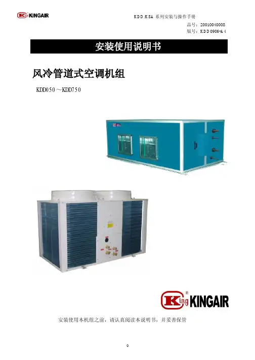
风冷管道式空调机组操作手册致用户1、在安装使用本设备之前,请阅读本手册。
阅读后,请妥善保管好本手册,以备今后参考。
安装和维修需有熟悉国家和当地安全规范的专业人员承担。
如果在安装维修及使用中未能遵守本手册所包含的说明和注意事项及安全规范,可能导致设备的损坏或财产损失,并且有可能造成操作人员的伤害。
最好的预防是正确的安装、正确的操作和经常性的维护与保养。
2、本手册在出版时具有准确性,但由于产品不断改,本公司保留未经通知更改产品技术数据的权力,并不因此承担任何义务。
3、在阅读本手册中,如果您需技术咨询,请您与总代理或当地代理商联系。
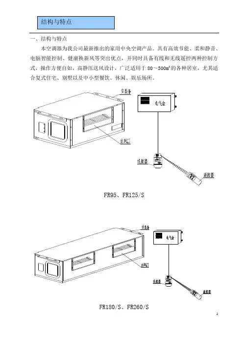
产品简介二、产品特点※适用范围广可满足工商业的各项需要,方便地安装在会议室、中小型商场、工厂办公室、试验室、小型厂房、公寓套房等多种场所。
室外机可以安装在地坪、屋顶等多种地方。
※运行宁静一方面,采用国际知名品牌的全封闭压缩机,并加装减震器,系统管道经过精心设计,另一方面,室外机采用大扭角大口径风叶,室内机组配置低噪声离心风机,送风效能卓越,运行宁静。
※优良的送风状态,风速随意调节,方便自在在机组进风侧接上新风管后,健康新风会源源导入,能大大改善您的工作和生活环境,同时,三档风速随意调节,高、中、低、自动四种送风状态,能满足您不同场合的需要。
※运行可靠,能效高机组核心部件采用国际知名品牌产品,压缩机采用谷轮、大金等国际知名品牌产品,同样其他一些部件如四通阀、膨胀阀等也都是国际知名品牌。
每一件材料都经过严格的检验才能进入装配线,每台机组出厂前均经过严格的性能测试,质量上严格把关,保证机器的可靠性。
※高雅、华丽、舒适当空调机接上风道,安装在天花板上,屋内只有风口在外,显得典雅和华丽。
同时,微电脑的恒温控制能更准确地控制室温,因此也更节能,同时增加了舒适感。
※控制完整、操作简单机组控制系统包括压缩机过载过热保护、逆缺相保护、制冷系统高、低压保护等多种安全保护措施,确保运行安全。
同时,微电脑的自动控制功能也十分完善,令您操作十分简单。
安装前的准备警告:防备大风、地震。
按规定进行安装。
安装不当,会因空调翻倒等造成事故。
制冷剂配管导管作业室内机组的安装修理只能由专业维修人员进行。
在接触接线装置之前,必须切断所有电源;只有在关机并切断电源后才可清洁空调器,否则可能触电或受伤。
清洁空调器时要特别注意:使用稳固的站立台;不可直接用水冲洗空调,否则可能触电。
注意清洗空气过滤器清洗出风口及外壳线控器功能说明①线控器初始化过程:线控器使用②其它部件名称及使用方法见操作指导。
③线控器的特殊功能:上电/复位后,线控器全显后,→→→循环显示,同时绿灯闪烁,直至初始化结束。
实际值,十进制数据类型进制实际值,十进制实际值,十进制实际值,十进制实际值,十六进制实际值,十六进制A.故障查询在非屏保状态下,长按定时键持续 5 秒,进行组内所有室内机的故障查询,左上角冒号后面显示机号(机号用十进制表示),通过左右键选择机号,右上角冒号前显示当前故障,冒号后显示历史故障(机号用十进制表示,故障用十六进制显示,故障代码中,十六进制为大写,但是其中 b 和 d 小写表示,避免和 8 混淆);故障查询阶段,按功能键退出故障查询状态。
B .故障履历清除:长按定时键持续 5 秒,显示故障,显示故障阶段长按“定时”持续 5 秒,清除当前故障和历史故障,包含所有机号的故障。
C.参数查看:在通常状态下,长按功能键持续 5 秒,则进入参数查看状态,左上角定时开 on 前面的两个 88 字段显示机号,可以通过定时键选择机号,右上角定时关区域的前两个 88 显示数据类型(即 A 、b 、C 、d 、E 、F ),后面两个88显示实际值。
如 00 号机的环温为 16 度,显示格式为“00 A 16”,按左右键可以进行数据类型选择。
类型含义A b C d E F室内传感器Tai 的温度室内传感器Tc1的温度室内传感器Tc2的温度室内机的PMV 开度/2室内机地址室内机集中地址在参数查看状态下,再次按功能键或连续 10 秒无按键操作,退出参数查看状态。


技术服务手册目录一、产品篇1、产品种类2、产品命名规则3、产品特点4、产品技术参数表5、产品性能修正表6、产品工作原理与控制工作原理机组的控制7、机组安装要求二、控制篇1、线控器的操作三、维修篇1、机组故障表2、典型故障排查3、维修案例4、机组配电5、关键部件及拆装6、爆炸图及零部件清单风管机科龙风管机是科龙户式中央空调的系列产品之一,他把中央空调领域里的先进制冷技术和各种空气处 理形式相结合,打破了传统中央空调与家用空调之间的界河。
该产品博采众长,汇聚了国内外同类产品的 优点,通过工作人员的精心设计、精心制造,具有外形美观、换热效率高、运行平稳、噪声低、高效节能、 维修保养方便等特点。
风管机系列户式中央空调机组作为科龙户式中央空调系列产品之一,提供单冷和热泵两类机型,共有 8个型号,制冷量从 2.5到12,制热量从2.7到12.5。
第一节产品概述使用环境温度条件: -5 C 〜43 C电源条件: 220 ± 10% 50 ± 1结构:系列风管机是科龙新开发的户式中央空调产品,室内机、电器部件、控制系统为全新开发,室 外机为科龙家用空调室外机。
第二节制冷系统图及特点25\35\50\70 (新型号分别为:25\35\50\70 )单冷风管机制冷系统图室内侧室外侧— 制冷循环制冷剂流向风扇 电 机风 扇 电 机25\35\50\70 (新型号分别为:25\35\50\70 )热泵风管机制冷系统图室内侧—制冷循环制冷剂流向 --制热循环制冷剂流向120 (新型号分别为:120)单冷风管机制冷系统图120 (新型号分别为:120)热泵风管机制冷系统图室内换热器室外换热器单向阀截止阀 截止阀风 扇 电 机室内换热器风 扇 电 机室外换热器风 扇 M电 机室内侧—■制冷循环制冷剂流向室外侧室外侧22室内侧一制冷循环制冷剂流向制热循环制冷剂流向第四节控制器操作说明一控制面板(如图1)△「调温—I希}睡眠12131415161718192021室内换热器室外换热器风扇电机室外侧风扇电机控制键液晶显示画面6 定时键 1 制热模式9 风扇控制键 2 除湿模式15 模式键 3 吹风模式18 温度调节键 4 定时开关21 睡眠键 5 定时显示和房间温度显示22 开/关键7 室内风机风速运行显示8 参数设置显示12 制冷模式13 自动模式14 除霜显示16 报警显示输出17 设定温度值显示10 工作指示灯19 辅助电加热睡眠显示11 遥控接收头20二、操作指示⑴开/关键:♦停止时按下开/关键,本机组进入运行状态,工作指示灯亮。

风管机安装维修手册风管机安装维修手册本文档旨在提供详细的风管机安装和维修指南,以帮助安装人员和维修人员正确进行操作。
请按照以下章节逐步执行相关步骤。
目录:1.风管机介绍1.1 机器概述1.2 技术规格1.3 安全要求2.安装流程2.1 安装前准备2.2 安装位置选择和准备2.3 风管机安装步骤2.3.1 连接电源2.3.2 连接管道2.3.3 设置风速和温度2.4 安全检查和测试3.维护与保养3.1 定期维护计划 3.2 清洁过滤器3.3 检查电气连接 3.4 检查管道连接 3.5 定期替换零件3.6 故障排除4.常见故障和解决方法 4.1 机器无法启动 4.2 温度不稳定4.3 风力不足4.4 异常噪音附件:1.安装图纸和说明书2.维修记录表格3.安全操作手册法律名词及注释:1.安全要求:指安装和维修过程中必须遵守的相关安全规定,以确保工作人员和设备的安全。
2.机器概述:对风管机的整体结构和功能进行详细说明。
3.技术规格:列出了风管机的技术参数,包括尺寸、功率、风量等。
4.安装前准备:介绍了进行风管机安装之前需要做的准备工作,如搬运设备、检查零部件等。
5.安装位置选择和准备:指导安装人员如何选择合适的位置并进行相应的准备工作。
6.安全检查和测试:在安装完成后,对所安装的风管机进行全面的安全检查和功能测试,以确保其正常工作。
7.定期维护计划:制定风管机的定期维护计划,以确保设备的长期运行稳定。
8.清洁过滤器:详细说明了如何清洁风管机的过滤器,以确保其正常运行和空气质量。
9.检查电气连接:介绍了对风管机的电气连接进行定期检查的步骤和注意事项。
10.检查管道连接:指导维修人员对风管机的管道连接进行检查和维护,以确保风力正常传输和不发生泄漏。
11.定期替换零件:了常见需要定期更换的风管机零件,并说明了更换的步骤。
12.故障排除:详细介绍了风管机常见故障的识别和解决方法,以便维修人员能够快速解决故障情况。

PART NO. 9373385066-02E n g l i s hINSTALLATION MANUALVRF SYSTEM INDOOR UNIT Duct TypeFor authorized service personnel only.Contents1. SAFETY PRECAUTIONS .............................................22. ABOUT THE UNIT2.1. Precautions for using the R410A refrigerant ..........22.2. Special tool for R410A ............................................22.3. Accessories ............................................................22.4. Optional parts .........................................................33. INSTALLATION WORK3.1. Selecting an installation location ............................33.2. Installation dimensions ...........................................43.3. Installing the unit ....................................................44. PIPE INSTALLATION4.1. Selecting the pipe material .....................................74.2. Pipe requirement ....................................................74.3. Flare connection (pipe connection) ........................74.4. Installing heat insulation .........................................85. INSTALLING DRAIN PIPES (8)6. ELECTRICAL WIRING6.1. Electrical requirement ..........................................106.2. Wiring method ......................................................116.3. Unit wiring ............................................................116.4. Connection of wiring .............................................136.5. Air fl ow changing ..................................................137. FIELD SETTING7.1. Setting the address ..............................................147.2. Custom code setting ............................................157.3. Function setting ....................................................168. TEST OPERATION8.1. Test operation using PCB (Outdoor unit) .............178.2. Test operation using Remote Controller ...............179. CHECK LIST ...............................................................1710. ERROR CODES (17)1. SAFETY PRECAUTIONS• Be sure to read this Manual thoroughly before installation.• The warnings and precautions indicated in this Manual contain important information pertaining to your safety. Be sure to observe them.• Hand this Manual, together with the Operating Manual to the customer.Request the customer to keep them on hand for future use, such as for relocating or repairing the unit.WARNING!This mark indicates procedures which, if improperly performed, might lead to the death or serious injury of the user.• Request your dealer or a professional installer to install the unit in accordance with this Manual.An improperly installed unit can cause serious accidents such as water leakage, electric shock, or fi re.If the unit is installed in disregard of the instructions in the Installation Manual, it will void the manufacturer’s warranty.• Do not turn ON the power until all work has been completed.Turning ON the power before the work is completed can cause serious accidents such as electric shock or fi re.• If refrigerant leaks while work is being carried out, ventilate the area.If the refrigerant comes in contact with a flame, it produces a toxic gas.• Installation work must be performed in accordance with national wiring standards by authorized personnel only.CAUTION!This mark indicates procedures which, if improperly performed, might possibly result in personal harm to the user, or damage to property.2. ABOUT THE UNIT2.1. Precautions for using the R410ArefrigerantWARNING• Do not introduce any substance other than the prescribed refrigerant into the refrigeration cycle.If air enters the refrigeration cycle, the pressure in the refrigeration cycle will become abnormally high and cause the piping to rupture.• If there is a refrigerant leakage, make sure that it does not exceed the concentration limit.If a refrigerant leakage exceeds the concentration limit, it can lead to accidents such as oxygen starvation.• Do not touch refrigerant that has leaked from the refrigerant pipe connections or other area. Touching the refrigerant directly can cause frostbite.• If a refrigerant leakage occurs during operation, immediately vacate the premises and thoroughly ventilate the area.If the refrigerant comes in contact with a flame, it produces a toxic gas.2.2. Special tool for R410AWARNING• To install a unit that uses the R410A refrigerant, use dedicated tools and piping materials that have been manufactured specifi cally for R410A use.Because the pressure of the R410A refrigerant is approximately 1.6 times higher than the R22, failure to use dedicated piping material or improper installation can cause rupture or injury.Furthermore, it can cause serious accidents such as water leakage, electric shock, or fi re.Tool name Contents of changeGauge manifold• Pressure is huge and cannot bemeasured with a conventional gauge.To prevent erroneous mixing of otherrefrigerants, the diameter of each porthas been changed.It is recommended to use a gaugemanifold with a high pressure displayrange –0.1 to 5.3 MPa and a lowpressure display range –0.1 to 3.8 MPa. Charging hose• To increase pressure resistance, thehose material and base size werechanged.Vacuum pump• A conventional vacuum pump can beused by installing a vacuum pumpadapter.Gas leakagedetector• Special gas leakage detector for HFCrefrigerant R410A.2.3. AccessoriesWARNING• For installation purposes, be sure to use the parts supplied by the manufacturer or other prescribed parts.The use of non-prescribed parts can cause serious accidents such as the unit to fall, water leakage, electric shock, or fi re.• The following installation parts are furnished. Use them as required.• Keep the Installation Manual in a safe place and do not discard any other accessories until the installation work has been completed.En-2Binder (Medium)Coupler heat insulation (Small)Coupler heat insulation (Large)Special nut A(Large flange)Special nut B(Small flange)HangerHose bandDrain hose insulationEn-4CAUTION• Do not use the unit for special purposes, such as storing food, raising animals, growing plants, or preserving precision devices or art objects.It can degrade the quality of the preserved or stored objects.• Do not install where there is the danger of combustible gas leakage.• Do not install the unit near a source of heat, steam, or fl ammable gas.• Install the unit where drainage does not cause any trouble.• Install the indoor unit, outdoor unit, power supply cable, transmission cable, and remote control cable at least 1 m away from a television or radio receivers. The purpose of this is to prevent TV reception interference or radio noise.(Even if they are installed more than 1 m apart, you could still receive noise under some signal conditions.)• If children under 10 years old may approach the unit, take preventive measures so that they cannot reach the unit.• Decide the mounting position with the customer as follows:(1) Install the indoor unit on a place having a suf fi cient strength so that it withstands against the weight of the indoor unit.(2) The inlet and outlet ports should not be obstructed; the air should be able to blow all over the room.(3) Leave the space required to service the air conditioner.(4) A place from where the air can be distributed evenly throughout the room by the unit.(5) Install the unit where connection to the outdoor unit is easy.(6) Install the unit where the connection pipe can be easily installed.(7) Install the unit where the drain pipe can be easily installed.(8) Install the unit where noise and vibrations are not ampli fi ed.(9) Take servicing, etc., into consideration and leave the spaces. Also install the unit where the fi lter can be removed.(10) Providing as much space as possible between the indoorunit and the ceiling will make work much easier.(11) If installing in a place where its humidity exceeds 80%, useheat insulation to prevent condensation.3.2. Installation dimensions• Provide the space around the unit as shown in the following fi gure.400 mm or more 150 mm or more ❈1❈1 400mm or more when drain from drain pipe.• Provide a service hole for inspection purposes.• Do not place any wiring or illumination in the service space, as they will impede service.• When an air fi lter is installed on the air inlet, provide enough service space to replace the fi lter.AirAirService holeControl box300 mmor more 500 mm or more500 m m o r m o r e100 m mAir AirService spaceControl box300 mm or more1,550 mm or more500 m m o r m o r e100 m mIntake panel3.3. Installing the unitWARNING• Install the air conditioner in a location which can withstand a load do at least fi ve times the weight of the main unit and which will not amplify sound or vibration. If the installation location is not strong enough, the indoor unit may fall and cause injuries.• If the job is done with the panel frame only, there is a risk that the unit will come loose. Please take care.3.3.1. Installing the hangersHanging bolt installation diagram.(Top side)(Right side)270 m mA i rA i rWARNING• When fastening the hangers, make the bolt positionsuniform.740 mm477 mmA i rA i r1,135 m m1,177 m mDuct installation pattern ( CUT PART)Cut Cut Cut Cut(2) Turn up the insulation around the points to be cut ac-cording to the outlet port shape working points so thatthe insulation does not stick out at the(3) Cut with nippers and remove the sheet metal.• The screw holes to install the flange are located behind the round cutouts in the insulation.Duct4.PIPE INSTALLATIONCAUTION• Be more careful that foreign matter (oil, water, etc.) does not enter the piping than with refrigerant R410A models. Also, when storing the piping, securely seal the openings by pinching, taping, etc.• While welding the pipes, be sure to blow dry nitrogen gas through them.4.1. Selecting the pipe materialCAUTION• Do not use existing pipes.• Use pipes that have clean external and internal sides without any contamination which may cause trouble during use, such as sulfur, oxide, dust, cutting waste, oil, or water.• It is necessary to use seamless copper pipes.Material : Phosphor deoxidized seamless copper pipesIt is desirable that the amount of residual oil is less than 40 mg/10 m.• Do not use copper pipes that have a collapsed, deformed, or discolored portion (especially on the interior surface). Otherwise, the expansion valve or capillary tube may become blocked with contaminants.• Improper pipe selection will degrade performance. As an air conditioner using R410A incurs pressure higher than when using conventional refrigerant, it is necessary to choose adequate materials.• Thicknesses of copper pipes used with R410A are as shown in the table.• Never use copper pipes thinner than those indicated in the table even if they are available on the market. Thicknesses of Annealed Copper Pipes (R410A)Pipe outside diameter [mm (in.)]Thickness [mm]6.35 (1/4)0.809.52 (3/8)0.8012.70 (1/2)0.8015.88 (5/8) 1.0019.05 (3/4) 1.204.2. Pipe requirementCAUTION• Refer to the Installation Manual of the outdoor unit for description of the length of connecting pipe or for difference of its elevation.• Use pipe with water-resistant heat insulation.CAUTION• Install heat insulation around both the gas and liquid pipes.Failure to do so may cause water leaks.Use heat insulation with heat resistance above 120 °C.(Reverse cycle model only)In addition, if the humidity level at the installation location of the refrigerant piping is expected to exceed 70 %, install heat insulation around the refrigerant piping. If the expected humidity level is 70-80 %, use heat insulation that is 15 mm or thicker and if the expected humidity exceeds 80 %, use heat insulation that is 20 mm or thicker. If heat insulation is used that is not as thick as specified, condensation may form on the surface of the insulation. In addition, use heat insulation with heat conductivity of 0.045 W/(m·K) or less (at20 °C).4.3. Flare connection (pipe connection)WARNING• Tighten the flare nuts with a torque wrench using the specified tightening method. Otherwise, the flare nuts could break after a prolonged period, causing refrigerant to leak and generate a hazardous gas if the refrigerant comes into contact with a fl ame.4.3.1. Flaring• Use special pipe cutter and fl are tool exclusive for R410A. (1) Cut the connection pipe to the necessary length with apipe cutter.(2) Hold the pipe downward so that cuttings will not enter thepipe and remove any burrs.(3) Insert the fl are nut (always use the fl are nut attached tothe indoor and outdoor units respectively) onto the pipeand perform the flare processing with a flare tool. Usethe special R410A flare tool, or the conventional flaretool. Leakage of refrigerant may result if other fl are nutsare used.(4) Protect the pipes by pinching them or with tape toprevent dust, dirt, or water from entering the pipes.BDieAPipeCheck if [L] is flared uniformlyand is not cracked or scratched.LEn-7Width across4.3.2. Bending pipesIf pipes are shaped by hand, be careful not to collapsethem.Do not bend the pipes in an angle more than 90°.When pipes are repeatedly bend or stretched, the material will harden, making it dif more.Do not bend or stretch the pipes more than three times.Connection pipeTorque wrenchIndoor unit pipe Flare nutHolding wrenchTighten with two wrenches.(Accessories)Binder (Large)(Accessories)Heat insulationheat insulation.CAUTION• After checking for gas leaks (refer to the Installation Manual of the outdoor unit), perform this section.• Install heat insulation around both the large (gas) and small (liquid) pipes. Failure to do so may cause water leaks.INSTALLING DRAIN PIPESUse general hard polyvinyl chloride pipe and connect it withadhesive (polyvinyl chloride) so that there is no leakage.Always heat insulate the indoor side of the drain e a drain hose that matches the size of the drain pipe.Do not perform a rise, trap and air bleeding.Provide a downward gradient (1/100 or more).Provide supporters when long pipes are installed.Use an insulation material as needed, to prevent the pipes from freezing.Install the pipes in a way that allows for the removal of the control box.Drain port Drain cap(Accessories)• Cover the drain cap with the drain hose insulation.Drain hose insulation (Accessories)Unit Unit Drain hose insulation (Accessories)Drain cap0 mmINSTALL THE DRAIN HOSEWorking procedure1) Install the attached drain hose to the drain port of the body.Install the hose band from the top of the hose within the graphic display area. Secure fi rmly with the hose brnd.2) Use vinyl adhesive agent to glue the drain piping (PVC pipe VP25) which is prepared on site or socket. (Apply color ad-hesive agent evenly until the gauge line and seal)3) Check the drainage.4) Install the heat insulation.5) Use the attached heat insulation to insulate the drain port and band parts of the body.DrainhoseArrange the drain hoselower than this portionTrapNO GOODOKRiseNO GOOD1.5 to2.0 mAir bleedingNO GOODCAUTION• Always check that the drain cap is installed to the unused drain port and is fastened with the binder.If the drain cap is not installed, or is not suffi ciently fastened by the binder, water may drip during the cooling operation.6.ELECTRICAL WIRING6. E L E C T R I C A L WWARNING• Electrical work must be performed in accordance with this Manual by a person certified under the national or regional regulations. Be sure to use a dedicated circuit for the unit.An insufficient power supply circuit or improperly performed electrical work can cause serious accidents such as electric shock or fi re.• Before starting work, check that power is not being supplied to the indoor unit and outdoor unit.• For wiring, use the prescribed type of wires, connect themEn-116.2. Wiring method(EXAMPLE)PR SUPPLY OUTDOOR UNIT TRANSMISSIONTRANSMISSION TRANSMISSION POWER SUPPLYPOWER SUPPLY POWER SUPPLYPOWER SUPPLYPOWER SUPPLYREMOTE CONTROL UNIT (MASTER)REMOTE CONTROL UNIT (SLAVE)REMOTE CONTROL UNITREMOTE CONTROLINDOOR UNITINDOOR UNIT INDOOR UNITBREAKERBREAKER POWER SUPPLY REMOTE CONTROLPOWER SUPPLY REMOTE CONTROLBREAKER BREAKERTRANSMISSION 6.3. Unit wiring• Before attaching the cable to terminal block.6.3.1. Power supply cablePower supply cable25 mm Earth cable30m m A. For solid core wiring(1) To connect the electrical terminal, follow the below diagram and connect after looping it around the end of the cable. (2) Use the speci fi ed cables, connect them securely, and fasten them so that there is no stress placed on the terminals.(3) Use an appropriate screwdriver to tighten the terminal screws. Do not use a screwdriver that is too small, otherwise, the screw heads may be damaged and prevent the screws from being properly tightened.(4) Do not tighten the terminal screws too much, otherwise, the screws may break.(5) See the table for the terminal screw tightening torques.(6) Please do not fi x two power supply cables with one screw.St ri p 25 mmLoop Screw with spe-cial washerScrew with special washer Cable end(Loop)Cable end (Loop)CableCableTerminal blockWARNING• When using solid core cables, do not use the ring terminal. If you use the solid core cables with the ring terminal, the ring terminal's pressure bonding may malfunction and cause the cables to abnormally heat up.B. For strand wiring(1) Use ring terminals with insulating sleeves as shown in the fi gure below to connect to the terminal block.(2) Securely clamp the ring terminals to the cables using an appropriate tool so that the cables do not come loose.(3) Use the speci fi ed cables, connect them securely, and fasten them so that there is no stress placed on the terminals.(4) Use an appropriate screwdriver to tighten the terminal screws. Do not use a screwdriver that is too small, otherwise, the screw heads may be damaged and prevent the screws from being properly tightened.(5) Do not tighten the terminal screws too much, otherwise, the screws may break.(6) See the table for the terminal screw tightening torques.(7) Please do not fi x two power supply cables with one screw.St r i p10 mmSleeveScrew with special washerScrew with special washerRing terminalCableCableTerminal blockRing terminalRing terminalWARNING• Use ring terminals and tighten the terminal screws to thespeci fi ed torques, otherwise, abnormal overheating may be produced and possibly cause heavy damage inside the unit.Tightening torqueM4 screw(Power supply /L, N, GND) 1.2 to 1.8 N·m (12 to 18 kgf·cm)En-126.3.2. Transmission and Remote control cableTransmission cableShielded cable (No fi lm)20 mm 45m mRemote control cable20 m m• Connect remote control and transmission cables as shown in Fig. A.Fig. AScrew Terminal blockCableCable of the same caliber: OKCable of the different caliber: NO GOODWARNING• Tighten the terminal screws to the specified torques, otherwise, abnormal overheating may be produced and possibly cause heavy damage inside the unit.Tightening torqueM3.5 screw(Transmission /X1, X2)(Remote control /Y1, Y2, Y3)0.8 to 1.0 N·m (8 to 10 kgf·cm)CAUTION• To peel the fi lm from the lead cable, use a dedicated tool that will not damage the conductor cable.• When installing a screw on the terminal block, do not cut the cable by overtightening the screw. On the other hand, an undertightened screw can cause faulty contact, which will lead to a communication failure.En-136.4. Connection of wiring(1) Remove the control box cover and install each connection cable.ScrewControl box cover(2) After wiring is complete, secure the remote control cable, connection cable, and power cable with the cable clamps.Power supply cable (Field supply)Binder (Medium) (Accessories)Binder (Medium) (Accessories)Remote control cable Transmission cable (Field supply)Binder (Medium) (Accessories)L, N:Power supply cableX1, X2:Transmission cableRemote control cable Y1:Red Y2:White Y3:Black6.5. Air fl ow changingWhen using the ARXB24/30/36/45L model with external Static Pressure under 40 Pa, the Wire (FAN MOTOR) must be replaced as explained below.Replacement method (1) Remove the cover.(2) Remove the Wire (TYPE A) connector from Wire (FAN MOTOR).(3) Remove the Wire (TYPE A) connector from CN4 of the PCB.(4) Insert the Wire (TYPE B) connector into CN4 of the PCB.(5) Insert the Wire (TYPE B) connector into Wire (FAN MOTOR).(6) Insert the cover.En-147.1. Setting the addressCAUTION• Use an insulated screwdriver to set the dip switches.Rotary switch Example: “0”Dip switch “SET 3”Rotary switch Example: “0”SW 1SW 2SW 3SW 4SettingSetting rangeType of switchIndoor unit address0–63Setting example2IU AD X 10 IU AD X 1Refrigerant circuit address0–99Setting example 63REF AD X 10 REF AD X 1(1) Indoor unit addressRotary switch (IU AD x 1)...Factory setting “0” Rotary switch (IU AD x 10)...Factory setting “0”When connecting multiple indoor units to one refrigerant system, set the address at IU AD SW as shown in the T able A.(2) Refrigerant circuit addressRotary switch (REF AD x 1)...Factory setting “0” Rotary switch (REF AD x 10)...Factory setting “0”In the case of multiple refrigerant systems, set REF AD SW as shown in the Table A for each refrigerant system.Set to the same refrigerant circuit address as the outdoor unit.• If working in an environment where the wireless remote controller can be used, the addresses can also be set using the remote controller.• If setting the addresses using the wireless remotecontroller, set the indoor unit address and refrigerant circuit address to “00”.(For information on setting using the wireless remote controller.)CoverWire (Fan motor)External Static Pressure and Required Connector TypeType ABExternal Static Pressure40 – 80 Pa0 – 40 PaWire123456123451 BLACK2 WHITE3 PINK4 PURPLE5 BLUEARXB24 ARXB30 ARXB361 BLACK 2 WHITE 3 RED 4 BLUE 5 PINK 6 PURPLEARXB451 BLACK2 WHITE3 RED4 PINK5 PURPLE6 BLUERemarkFactory setting (Standard static pressure)Accessories (Low static pres-sure)7. FIELD SETTING• Refer to the following three items for setting the FIELD SETTING address. The respective settings are included below.(1) IU AD, REF AD SW settings ............ T his section (2) Remote control settings ................... R efer to the wired orwireless remote control manual for detailed set-ting information. (Set IU AD, REF AD SW to 0)(3) Automatic address settings .............. R efer to the indoor unitmanual for detailed set-ting information. (Set IU AD, REF AD SW to 0)CAUTION• Be sure to turn OFF the power before performing the fi eld setting.Table AAddressRotarySwitch SettingAddressRotarySwitch SettingRefrigerant circuit REF AD SWIndoor unitIU AD SW x 10x 1x 10x 1000000 101101 202202 303303 404404 505505 606606 707707 808808 909909 10101010 11111111 12121212.. ................99996363 Do not set the indoor unit address (IU AD SW) at 64 to 99. It may result failure.RC AD SWRC AD SW1RC AD SW2RC AD SW3Indoor unitRemotecontrollerIndoor unit Indoor unit Indoor unitA B C DA B C D IndoorunitRemotecontrollerConfusionCode change(3) Remote controller addressRotary switch (RC AD SW)...Factory setting “0”When connecting multiple indoor units to one standard wired remote controller, set the address at RC AD SW in sequence from 0.SettingSettingrangeType of switchRemotecontrolleraddress0–15SettingexampleRC ADExample If 4 indoor units are connected.RC AD SW01234567 Address01234567RC AD SW89A B C D E F Address891011121314157.2. Custom code settingSelecting the custom code prevents the indoor unit mix-up.(Up to 4 codes can be set.)Perform the setting for both the indoor unit and the remote controller.En-15En-16Function detailsFunctionFunction numberSetting number DefaultDetailsFilter indicator interval1100Default ○Adjust the fi lter cleaning interval noti fi cation. If the noti fi cation is too early, change to setting 01. If the noti fi cation is too late, change to setting 02.01Longer 02Shorter Filter indicator action1300Enable ○Enable or disable the fi lter indicator. Setting 02 is for use with a central remote control.01Disable 02Display only on central remote control Horizontal swing air fl ow direction2400Default ○Adjust the horizontal swing air fl ow direction.(For horizontal swing equipped models)01Left half 02Right half Cool air temperature trigger3000Default ○Adjust the cool air trigger temperature. To lower the trigger temperature, use setting 01. To raise the trigger temperature, use setting 02.01Adjust (1)02Adjust (2)Hot air temperature trigger3100Default ○Adjust the hot air trigger temperature. To lower the trigger temperature by 6 degrees C, use setting 01. To lower the trigger temperature by 4 degrees C, use setting 02. To raise the trigger temperature, use setting 03.01Adjust (1)02Adjust (2)03Adjust (3)Auto restart4000Enable Enable or disable auto-matic system restart after a power outage.01Disable○External control4600Start/Stop○Allow an external control-ler to start or stop the system, or to perform an emergency shutdown.* I f an emergency shut-down is performed from an external controller, all refrigerant systems will be disabled.01Emergen-cy stopError report target4700All ○Change the target for reporting errors. Errors can either be reported in all locations, or only on the wired remote.01Display only on central remote control• Custom code setting for indoor unitSet the DIP SW SET 3 SW1, SW2, referring to the Table B.Dip switch “SET 3”SW 1SW 2SW 3SW 4OFFON Table BCustom codeA (Factory setting)BC D DIP SWSET 3 SW1OFF ON OFF ON DIP SW SET 3 SW2OFFOFFONON7.3. Function setting• FUNCTION SETTING can be performed with the wired or wireless remote control.(The remote control is optional equipment)• Refer to the wired or wireless remote control manual for detailed setting information. (Set IU AD, REF AD SW to 0)• Refer to “7.1. Setting the address” for indoor unit ad-dress and refrigerant circuit address settings.• T urn the power of the indoor unit ON before starting the setting.* Turning on the power indoor units initializes EEV , so make sure the piping air tight test and vacuuming have been conducted before turning on the power.* Also check again to make sure no wiring mis-takes were made before turning on the power.。
奥克斯中静压风管送风式空调(热泵)机组维修技术资料宁波奥克斯电气有限公司121-5-3、风系统示意图2 常规配线要求■注意:●所有电线和部件都是经过检测的。
●具体接线方法可参考室外机上所列的回路表。
●所有与电气有关的工作应由专业电工严格按照电工操作规程完成。
●回路表对于接线只提供大致情况,具体详情并没有体现。
●每个设备都要安装断路器和保险丝。
●连线不必过份用力,用罩子盖住电线或其他部件以免松动。
松动会引起 过热、短路或火灾。
2-2、内外机接线示意图:风冷冷凝器:热泵系统中化霜信号线为RVVP 300/300V 70o两端接头为ELR-02V。
建议当电源连接线不超过10m时采用RVV型护套线电缆; 当电源连接线超过10m时采用防水YZW型橡套软电缆;在有油污比较严重,采用防油RVVY软电缆。
2-3 静压调节本系列机组均有50/80Pa两种静压配置,机组出厂时均按低档静压配置,如安装时需要更高静压,只需把与电机电源线连接的接头由红色接头改为白色接头即可实现。
打开电控盒盖后即可调节机组静压,具体如下:四、控制器/线控器使用说明书4.1 控制器使用说明书本说明书适用于奥克斯商用空调S2款机型,且主芯片为MB89F202,本规格书内容有以下几个部分:一、控制器使用的基本条件;二、控制器的功能划分;三、主要功能说明;四、技术指标和要求;产品应严格符合本规格书的技术指标要求,凡与本规格书不符的应判为不合格品。
控制器使用的基本条件一、电源电压适用范围:输入电压175 V – 253V;二、交流输入电流频率:50Hz/60Hz;三、电控工作环境温度:(-10~+70)℃;四、电控工作环境湿度:RH20%~RH90%;五、室内风机为抽头电机,三档风速;六、室外风机为抽头铁壳电机,一档风速,正常工作电流小于3A;七、四通阀正常工作电流小于1A/220V AC;八、压缩机为单相电源,正常工作电流小于20A。
控制器的功能划分控制器的功能由以下几部分组成:一、遥控接收功能;3二、强制运行功能;三、蜂鸣器驱动功能;四、室内风机驱动功能;五、定时开、关机功能;六、压缩机再启动保护功能;七、制热模式下室内热交换器高温保护功能;八、制热模式下的外盘除霜和恢复制热功能;九、制热模式下防冷风功能;十、制冷、除湿模式下的防冻结功能;十一、自检功能。
第4章风管式空调系统安装与维修4.1 系统概述4.1.1安装综述 4.1.2系统特点 4.1.3使用常识 4.1.4日常维护4.2 风管制作与安装4.2.1风管材料 4.2.2风管尺寸 4.2.3风管保温 4.2.4风管制作及吊装4.3 室外机安装4.3.1安装位置 4.3.2配管及保护 4.3.3制冷剂(油)充注与调整 4.3.4电气安装4.4 室内机选用及安装4.4.1室内机选用 4.4.2安装位置 4.4.3不同出风方式 4.4.4冷凝水排放4.4.5电器连接4.5 消声静压箱选用及安装4.5.1噪声源 4.5.2消除、减弱噪声的方法 4.5.3消声器的类型4.5.4消声静压箱的选用及安装4.6 送、回风口选用安装4.6.1送、回风口的种类 4.6.2送、回风口位置的布置与安装4.6.3各种送、回风方式的特点 4.6.4送、回风口的风速要求4.7 隐蔽工程的验收4.7.1风管的验收 4.7.2制冷剂接管的验收 4.7.3凝水盘及冷凝水管的验收4.7.4室内机的试运行 4.7.5室内外机联合试运行4.8 调试与竣工验收4.8.1主温控器安装位置及使用4.8.2系统工作状况调试4.8.3风量及温升检测4.8.4系统各项指标的验收4.9 风管式空调系统常见故障分析及排除4.9.1故障检修表 4.9.2故障诊断4.10风管式空调系统故障诊断、排障实例4.10.1压缩机烧坏 4.10.2四通换向阀不换向 4.10.3高压保护 4.10.4制冷剂泄漏 4.10.5除霜装置不灵 4.10.6冷凝水滴漏 4.10.7内风机不转 4.10.8控制变压器烧坏第4章风管式空调系统安装与维修4.1 系统概述4.1.1 安装综述户式中央空调系统安装工程是一个综合性工程,要完成这项工程,除了要有优质的空调设备外,还需有良好的设计和安装、调试手段。
如果说设备的好坏只占整个系统质量的30%的话,那么,设计安装调试的好坏,则占系统质量的70%。