古瑞瓦特新能源光伏逆变器产品手册概要
- 格式:docx
- 大小:883.67 KB
- 文档页数:46

古瑞瓦特逆变器采集1.引言1.1 概述概述部分的内容可以包含对古瑞瓦特逆变器采集主题的简要介绍和背景信息。
可以按照以下方向来撰写:古瑞瓦特逆变器采集是一项重要的技术,在可再生能源领域扮演着关键的角色。
随着清洁能源的快速发展和应用范围的扩大,逆变器的采集功能越来越受到重视。
逆变器采集是指通过逆变器系统对特定能源进行数据采集和监测,以实现对能源转化效率、系统运行状态和能源利用率的监控和分析。
逆变器采集在可再生能源领域具有重要意义。
随着可再生能源的快速发展,如太阳能和风能等,逆变器采集成为了实现这些能源高效转化的关键环节。
逆变器采集不仅能实现对能源的实时监测和采集,还提供了数据分析和评估所需的基础。
通过逆变器采集,可再生能源的利用率可以得到提高,系统的运行状态和能源质量也可以得以监测和评估。
古瑞瓦特逆变器采集作为逆变器采集领域的重要技术,具备多种优势和特点。
首先,古瑞瓦特逆变器采集具有高效、稳定和可靠的数据采集能力,可以实时、准确地获取能源转化和输出的关键参数,如电流、电压、频率和功率等。
其次,古瑞瓦特逆变器采集还具备灵活多样的数据处理和传输方式,可以通过有线或无线的方式将采集到的数据传输至监控系统。
另外,古瑞瓦特逆变器采集还具备可扩展性和兼容性,可以与其他监控设备和系统进行接口连接,实现整体监测和控制。
通过本文的详细剖析和论述,将全面介绍古瑞瓦特逆变器采集的优势和重要性。
同时,也将展望未来逆变器采集的发展方向,探讨逆变器采集领域的挑战和机遇。
最终,本文旨在为读者提供关于古瑞瓦特逆变器采集的全面了解,以及对逆变器采集领域发展方向的思考和展望。
1.2文章结构1.2 文章结构本文将分为以下几个部分进行叙述。
首先,在引言部分,我们将对古瑞瓦特逆变器采集的概述进行介绍,阐述文章的目的和重要性。
接下来,在正文部分,我们将详细介绍古瑞瓦特逆变器的基本原理和特点,并重点强调逆变器采集数据的重要性。
在结论部分,我们将总结古瑞瓦特逆变器采集的优势,并展望未来逆变器采集的发展方向。


古瑞瓦特逆变器序列号-概述说明以及解释1.引言1.1 概述概述部分的内容可以着重介绍古瑞瓦特逆变器序列号的背景和重要性。
以下是一种可能的写作方向:概述在现代电力行业中,逆变器被广泛应用于将直流电转换为交流电的过程中。
作为逆变器中的重要组成部分,古瑞瓦特逆变器在可靠性和性能方面一直处于领先地位。
然而,为了确保逆变器在运行过程中的追踪、调试和保修工作能够有效进行,每个逆变器都被赋予了一个独特的序列号。
古瑞瓦特逆变器序列号可以被视为逆变器的id。
它具有唯一性,能够对逆变器进行准确的标识和追踪。
通过序列号,我们可以轻松地获取关于逆变器的相关信息,例如出厂日期、生产批次和技术参数等。
这对于工程师、维修人员和运营商来说都是非常重要的,因为它们为逆变器的监测、维护和管理提供了基础。
古瑞瓦特逆变器序列号的重要性不仅在于追踪逆变器的历史和技术信息,还在于保修和售后服务方面的便利性。
逆变器作为电力系统中的关键设备,其运行状态和故障信息对于运营商和维护人员来说至关重要。
通过序列号,我们可以快速定位和识别故障逆变器,并及时采取措施修复。
同时,在逆变器的保修过程中,序列号也起到了重要的作用,可以帮助生产厂家或供应商准确地识别产品并提供相关支持。
在本文的后续部分,我们将深入讨论古瑞瓦特逆变器序列号的具体组成和含义,以及对于序列号的正确使用与管理提出一些建议。
通过对古瑞瓦特逆变器序列号的全面了解,我们可以更好地利用和管理逆变器设备,并展望其未来发展的潜力和前景。
(注:本部分内容仅供参考,具体写作方式可以根据个人理解和实际情况进行调整。
)1.2 文章结构:本文主要按照以下结构进行展开:首先,引言部分将概述本文所要讨论的内容,即古瑞瓦特逆变器序列号的重要性以及其组成和含义。
引言还会明确文章结构和目的,让读者对文章有一个清晰的认识。
接着,正文部分将详细介绍古瑞瓦特逆变器的基本原理,包括逆变器的工作原理和其在能源转换中的作用。
同时,重点探讨古瑞瓦特逆变器序列号的重要性,解释为什么序列号对于逆变器的使用和管理至关重要。

古瑞瓦特光伏逆变器常见故障与处理方法1.故障:逆变器无法启动或无输出电流处理方法:-检查逆变器是否正确连接至电网。
确保光伏逆变器的交流输出端与电网入口连接牢固。
-检查直流输入电源供应是否正常。
确保逆变器的直流输入端连接的太阳能电池板电源正常。
-检查逆变器的保护装置是否触发。
如果逆变器的过温保护、短路保护或过载保护被触发,需要及时处理故障源。
2.故障:逆变器输出电压异常处理方法:-检查逆变器的输入电压是否正常。
确保光伏逆变器的直流输入端连接的太阳能电池板电源输出正常。
-检查逆变器的调节功能是否正常。
可能需要重新设置逆变器的输出电压和频率参数。
-如果光伏逆变器的输出电压仍然异常,可能是逆变器内部元件损坏,需要更换或修理逆变器。
3.故障:逆变器过热处理方法:-检查逆变器的散热系统是否正常。
清理逆变器周围的灰尘、杂物,确保散热片和风扇正常工作。
-如果逆变器在高温环境下长时间工作,可能需要增加逆变器的散热设备,如风扇或散热片。
-如果逆变器的过热保护装置被触发,需待逆变器冷却后再启动。
4.故障:逆变器频繁断电处理方法:-检查逆变器的电源输入是否稳定。
如果存在电源波动或电源供应不稳定的情况,可能需要安装稳定器或稳压装置。
-检查光伏逆变器的输出负载是否超过逆变器额定负载。
如果负载过大,需要减少负载或更换更高额定负载的逆变器。
-如果逆变器频繁断电且以上原因均排除,可能是逆变器本身存在故障,需要更换或修理逆变器。
5.故障:逆变器无法与监控系统通信处理方法:-检查逆变器与监控系统的通信线缆是否正常连接。
-检查逆变器的通信设置和监控系统的通信设置是否匹配。
-如果逆变器无法与监控系统通信且以上原因均排除,可能是逆变器通信模块存在故障,需要更换或修理逆变器。
总结:。
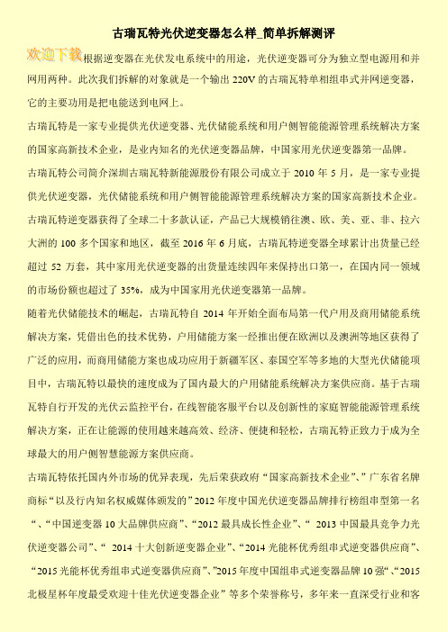
古瑞瓦特光伏逆变器怎么样_简单拆解测评根据逆变器在光伏发电系统中的用途,光伏逆变器可分为独立型电源用和并网用两种。
此次我们拆解的对象就是一个输出220V的古瑞瓦特单相组串式并网逆变器,它的主要功用是把电能送到电网上。
古瑞瓦特是一家专业提供光伏逆变器、光伏储能系统和用户侧智能能源管理系统解决方案的国家高新技术企业,是业内知名的光伏逆变器品牌,中国家用光伏逆变器第一品牌。
古瑞瓦特公司简介深圳古瑞瓦特新能源股份有限公司成立于2010年5月,是一家专业提供光伏逆变器,光伏储能系统和用户侧智能能源管理系统解决方案的国家高新技术企业。
古瑞瓦特逆变器获得了全球二十多款认证,产品已大规模销往澳、欧、美、亚、非、拉六大洲的100多个国家和地区,截至2016年6月底,古瑞瓦特逆变器全球累计出货量已经超过52万套,其中家用光伏逆变器的出货量连续四年来保持出口第一,在国内同一领域的市场份额也超过了35%,成为中国家用光伏逆变器第一品牌。
随着光伏储能技术的崛起,古瑞瓦特自2014年开始全面布局第一代户用及商用储能系统解决方案,凭借出色的技术优势,户用储能方案一经推出便在欧洲以及澳洲等地区获得了广泛的应用,而商用储能方案也成功应用于新疆军区、泰国空军等多地的大型光伏储能项目中,古瑞瓦特以最快的速度成为了国内最大的户用储能系统解决方案供应商。
基于古瑞瓦特自行开发的光伏云监控平台,在线智能客服平台以及创新性的家庭智能能源管理系统解决方案,正在让能源的使用越来越高效、经济、便捷和轻松,古瑞瓦特正致力于成为全球最大的用户侧智慧能源方案供应商。
古瑞瓦特依托国内外市场的优异表现,先后荣获政府“国家高新技术企业”、”广东省名牌商标“以及行内知名权威媒体颁发的”2012年度中国光伏逆变器品牌排行榜组串型第一名“、“中国逆变器10大品牌供应商”、“2012最具成长性企业”、“2013中国最具竞争力光伏逆变器公司”、“2014十大创新逆变器企业”、“2014光能杯优秀组串式逆变器供应商”、“2015光能杯优秀组串式逆变器供应商”、”2015年度中国组串式逆变器品牌10强“、“2015北极星杯年度最受欢迎十佳光伏逆变器企业”等多个荣誉称号,多年来一直深受行业和客。
古瑞瓦特逆变器安装说明_安装注意事项
古瑞瓦特UE系列光伏逆变器用于把光伏电池板产生的直流电转换成交流电并以三相方式输送给电网。
古瑞瓦特UE系列逆变器可以接2个组串,拥有2个最大功率追院点跟踪器因此适用于连接2组不同的电池板阵列。
本文主要介绍的是古瑞瓦特UE系列逆变器的安装说明及注意事项,具体的步骤教程跟随小编来了解一下。
一、安装前的安全说明1、安装前请仔细阅读本手册若未按本手册中的说明进行安装或者忽略说明书中的警告而出现设备损坏本公司有权不进行质量保证
2、所有操作和接线请专业电气或机械工程师操作
3、安装时除了接线端子外请不要动机箱内部的其它部分
4、所有电气安装必须符合当地电气安全标准
5、本机器如需要维护请联系当地指定系统安装和维护人员
6、使用本机器并网发电需获得当地供电部门允许
7、白天安装光伏组件时应用不透光的材料遮住光伏组件否则在阳光下组件端电压很高从而产生人身危险。
二、古瑞瓦特逆变器安装说明1、基本安装要求
该部分指导是提供给安装人员以选择合适的安装地点,避免损坏机器或者伤害操作人员。
A、安装逆变器的墙体必须要坚固并且能够长时间承受逆变器的重量。
B、安装地点必须符合逆变器的尺寸。
C、不要把逆变器安装在易燃或者不耐热材料建成的建筑物上。
D、机器的保护等级是IP65的在室内室外都可以安装。
E、为了避免逆变器由于过多而降低输出功率请不要把逆变器直接暴露在阳光下。
F、逆变器周围的环境温度应当在25*~ 60*之间。
G、逆变器可以安装在垂直或向后倾斜的平面上,请参考下图3.1。
古瑞瓦特光伏逆变器常见故障与处理方法
光伏逆变器作为一项电子产品,由众多元器件组成。
逆变器又称电源调整器,根据逆变器在光伏发电系统中的用途可分为独立型电源用和并网用二种。
根据波形调制方式又可分为方波逆变器、阶梯波逆变器、正弦波逆变器和组合式三相逆变器。
本文主要介绍了古瑞瓦特光伏逆变器常见故障与处理方法以及维修时的注意事项,具体的跟随小编一起来了解一下。
古瑞瓦特光伏逆变器常见故障与处理方法
1、绝缘阻抗低
使用排除法。
把逆变器输入侧的组串全部拔下,然后逐一接上,利用逆变器开机检测绝缘阻抗的功能,检测问题组串,找到问题组串后重点检查直流接头是否有水浸短接支架或者烧熔短接支架,另外还可以检查组件本身是否在边缘地方有黑斑烧毁导致组件通过边框漏电到地网。
User Manual Grid-Tied PV InverterHT Series(225-250kW)V1.1-2022-07-20Copyright Statement User Manual V1.1-2022-07-20The information in this user manual is subject to change due to product updates or other reasons. This manual cannot replace the product labels or the safety precautions unless otherwise specified. All descriptions in the manual are for guidance only.TrademarksNoticeand other GoodWe trademarks are trademarks of GoodWe Company.All other trademarks or registered trademarks mentioned in this manual are owned by GoodWe Technologies Co., Ltd.No part of this manual can be reproduced or transmitted to the public platform in any form or by any means without the prior written authorization of GoodWe Technologies Co., Ltd.Copyright ©GoodWe Technologies Co., Ltd., 2022. All rights reservedContent User Manual V1.1-2022-07-20 CONTENT1 About This Manual (1)1.1 Applicable Model (1)1.2 Target Audience (1)1.3 Symbol Definition (2)1.4 Updates (2)2 Safety Precaution (3)2.1 General Safety (3)2.2 DC Side (3)2.3 AC Side (4)2.4 Inverter Installation (4)2.5 Personal Requirements (4)3 Product Introduction (5)3.1 Application Scenarios (5)3.2 Supported Grid Types (5)3.3 Circuit Diagram (6)3.4 Appearance (8)3.4.1 Parts (8)3.4.2 Dimensions (10)3.4.3 Indicators (11)3.4.4 Nameplate (12)4 Check and Storage (13)4.1 Check Before Receiving (13)4.2 Deliverables (13)4.3 Storage (14)5 Installation (15)5.1 Installation Requirements (15)5.2 Inverter Installation (18)5.2.1 Moving the Inverter (18)5.2.2 Installing the Inverter (18)6 Electrical Connection (21)6.1 Safety Precautions (21)User Manual V1.1-2022-07-20Content 6.2 Connecting the PE Cable (24)6.3 Connecting the PV Input Cable (25)6.4 Connecting the AC Output Cable (28)6.5 Communication (30)6.5.1 Connecting the Communication Cable (30)6.5.2 Installing the Communication Module (34)7 Equipment Commissioning (35)7.1 Check Items Before Switching Power ON (35)7.2 Power On (35)8 System Commissioning (36)8.1 Indicators and Button (36)8.2 Setting Inverter Parameters via LCD (37)8.3 Setting Inverter Parameters via App (40)8.4 Monitoring via SEMS Portal (40)9 Maintenance (41)9.1 Power Off the Inverter (41)9.2 Removing the Inverter (41)9.3 Disposing of the Inverter (41)9.4 Troubleshooting (42)9.5 Routine Maintenance (48)10 Technical Parameters (49)User Manual V1.1-2022-07-2001 About This Manual1 About This ManualThis manual describes the product information, installation, electrical connection, commissioning, troubleshooting, and maintenance. Read through this manual before installing and operating the product. All the installers and users have to be familiar with the product features, functions, and safety precautions. This manual is subject to update without notice. For more product details and latest documents, visit .1.1 Applicable ModelThis manual applies to the listed inverters below (HT for short):1.2 Target AudienceThis manual applies to trained and knowledgeable technical professionals. The technical personnel has to be familiar with the product, local standards, and electric systems.01 About This Manual User Manual V1.1-2022-07-201.3 Symbol DefinitionDifferent levels of warning messages in this manual are defined as follows:1.4 UpdatesThe latest document contains all the updates made in earlier issues.V1.0 2022-05-04• First Issue.V1.1 2022-07-20• Updated technical parameters and electrical connections.User Manual V1.1-2022-07-2002 Safety Precaution 2 Safety Precaution2.1 General Safety2.2 DC Side02 Safety Precaution User Manual V1.1-2022-07-202.4 Inverter Installation2.5 Personal RequirementsUser Manual V1.1-2022-07-2003 Product Introduction3 Product Introduction3.1 Application ScenariosThe HT inverter is a three-phase PV string grid-tied inverter. The inverter converts the DC power generated by the PV module into AC power and feeds it into the utility grid. The intended use of the inverter is as follows:PV String Inverter Cabinet The grid structures supported by HT series GW250K-HT, GW250KN-HT, GW225K-HT and GW225KN-HT are IT, as shown in the figure below:3.2 Supported Grid TypesInverterTransformer ITL1L2L3PE03 Product Introduction User Manual V1.1-2022-07-20 3.3 Circuit DiagramThe circuit diagram of GW250K-HT , and GW225K-HT are as follows.User Manual V1.1-2022-07-2003 Product Introduction The circuit diagram of GW225KN-HT, and GW250KN-HT are as follows.03 Product Introduction User Manual V1.1-2022-07-20 3.4 Appearance3.4.1 PartsGW250K-HT , and GW225K-HTGW225KN-HT, and GW250KN-HTUser Manual V1.1-2022-07-2003 Product Introduction03 Product Introduction User Manual V1.1-2022-07-203.4.2 DimensionsUser Manual V1.1-2022-07-2003 Product Introduction 3.4.3 Indicators03 Product Introduction User Manual V1.1-2022-07-20 3.4.4 NameplateThe nameplate is for reference only.Technical parametersSafety symbols and certification marksContact information and serialnumberUser Manual V1.1-2022-07-2004 Check and Storage4 Check and Storage4.1 Check Before Receiving4.2 DeliverablesCheck the following items before receiving the product.1. Check the outer packing box for damage, such as holes, cracks, deformation, and others signs of equipment damage. Do not unpack the package and contact the supplier as soon as possible if any damage is found.2. Check the inverter model. If the inverter model is not what you requested, do not unpack the product and contact the supplier.3. Check the deliverables for correct model, complete contents, and intact appearance. Contact the supplier as soon as possible if any damage is found.04 Check and Storage User Manual V1.1-2022-07-20 4.3 StorageIf the equipment is not to be installed or used immediately, please ensure that the storage environment meets the following requirements:1. Do not unpack the outer package or throw the desiccant away.2. Store the equipment in a clean place. Make sure the temperature and humidity are appropriate and no condensation.3. The height and direction of the stacking inverters should follow the instructions on the packing box.4. The inverters must be stacked with caution to prevent them from falling.5. If the inverter has been long term stored, it should be checked by professionals before being put into use.User Manual V1.1-2022-07-2005 Installation5 Installation5.1 Installation RequirementsInstallation Environment Requirements1. Do not install the equipment in a place near flammable, explosive, or corrosive materials.2. Install the equipment on a surface that is solid enough to bear the inverter weight.3. Install the equipment in a well-ventilated place to ensure good dissipation. Also, theinstallation space should be large enough for operations.4. The equipment with a high ingress protection rating can be installed indoors or outdoors.The temperature and humidity at the installation site should be within the appropriate range.5. Install the equipment in a sheltered place to avoid direct sunlight, rain, and snow. Build asunshade if it is needed.6. Do not install the equipment in a place that is easy to touch, especially within children’sreach. High temperature exists when the equipment is working. Do not touch the surface to avoid burning.7. Install the equipment at a height that is convenient for operation and maintenance, electricalconnections, and checking indicators and labels.8. Install the inverters far away from noise-sensitive areas, such as the residential area, school,hospital etc., in order to avoid the noises bothering people nearby.9. Install the inverter away from high magnetic field to avoid electromagnetic interference.Ifthere is any radio or wireless communication equipment below 30MHz near the inverter, you have to:• Install the inverter at least 30m far away from the wireless equipment.• Add a low pass EMI filter or a multi winding ferrite core to the DC input cable or AC output cable of the inverter.Mounting Support Requirements1. The mounting support shall be nonflammable and fireproof.2. Make sure that the support surface is solid enough to bear the product weight load.3. Do not install the product on the support with poor sound insulation to avoid the noise generated by the working product, which may annoy the residents nearby.05 Installation User Manual V1.1-2022-07-20Installation Angle Requirements• Install the inverter vertically or at a minimum back tilt of 10 degrees.•Do not install the inverter upside down, forward tilt, back forward tilt, or horizontally.User Manual V1.1-2022-07-2005 Installation Installation Tool RequirementsThe following tools are recommended when installing the equipment. Use other auxiliary tools on site if necessary.05 Installation User Manual V1.1-2022-07-20Step 1 Put the mounting plate on the wall horizontally and mark positions for drilling holes.Step 2 Drill holes to a depth of 65mm using the hammer drill. The diameter of the drill bit should be 13mm.Step 3 Fix the mounting plate on the wall or the bracket.Step 4 Install the handles or the hoisting rings.Step 5 Grab the handles to lift the inverter or hoist the inverter to place it on the mounting plate.Step 6 Tighten the nuts to secure the mounting plate and the inverter.5.2 Inverter Installation5.2.2 Installing the Inverter5.2.1 Moving the InverterMounting on the wallUser Manual V1.1-2022-07-2005 Installation Mounting on the plateUser Manual V1.1-2022-07-2006 Electrical Connection 6 Electrical Connection6.1 Safety Precautions06 Electrical Connection User Manual V1.1-2022-07-20User Manual V1.1-2022-07-2006 Electrical Connection≤≤20mm≤Dimensions of the AC OT terminals after crimping:112mm06 Electrical Connection User Manual V1.1-2022-07-20 6.2 Connecting the PE CableUser Manual V1.1-2022-07-2006 Electrical Connection 6.3 Connecting the PV Input CableConnecting the DC Input CableStep 1 Prepare DC cables.Step 2 Crimp the crimp contacts.Step 3 Disassemble the PV connectors.Step 4 Make the DC cable and detect the DC input voltage.Step 5 Plug the PV connectors into the PV terminals.06 Electrical Connection User Manual V1.1-2022-07-20 Devalan DC ConnectorUser Manual V1.1-2022-07-2006 Electrical Connection MC4 DC Connector06 Electrical Connection User Manual V1.1-2022-07-20An AC circuit breaker should be installed on the AC side to make sure that the inverter can safety disconnect the grid when an exception happens. Select the appropriate AC circuit breaker in compliance with local laws and regulations. Recommended AC circuit breakers:Select and Install RCD depending on local laws and regulations.Type A RCDs (Residual Current Monitoring Device) can be connected to the outside of the inverter for protection when the DC component of the leakage current exceeds the limit value. The following RCDs are for reference: Step 1 Make the AC output cable.Step 2 Dismantle the AC cover and take out the rubber ring. Step 3 Cut the rubber ring to right size.Step 4 Crimp the AC cable OT terminalStep 5 Connect the AC output cables and install the cover.User Manual V1.1-2022-07-2006 Electrical ConnectionSingle-core cable:06 Electrical Connection User Manual V1.1-2022-07-206.5 Communication6.5.1 Connecting the Communication CableRouterRS485 networking scenarioConnect the RS485 port of the inverter to the Data Logger. The total length of the connection cable is less than 1000m.Keep the communication cable away from power cables to prevent the communication from being interrupted.If more than 2 inverters are connected and also connected to the data logger, at most 20 inverters are allowed on the daisy chain.InverterInverterInverterConnecting the RS485 Communication CableUser Manual V1.1-2022-07-2006 Electrical Connection06 Electrical Connection User Manual V1.1-2022-07-20Connecting the Remote Shutdown and Emergency Power Off Communication Cable Remote Shutdown and Emergency Power Off networking scenario Remote Shutdown or Emergency Power Off Remote Shutdown: For Europe only.Emergency Power Off: For India only.Remote Shutdown or Emergency Power OffRemote Shutdown or Emergency Power OffUser Manual V1.1-2022-07-2006 Electrical Connection06 Electrical Connection User Manual V1.1-2022-07-206.5.2 Installing the Communication ModulePlug a Bluetooth module into the inverter to establish a connection between the inverter and the smartphone or web pages. Set inverter parameters, check running information and fault information, and observe system status in time via the smartphone or web pages.User Manual V1.1-2022-07-2007 Equipment Commissioning7 Equipment Commissioning7.1 Check Items Before Switching Power ON7.2 Power OnStep 1 Turn on the AC breaker between the inverter and the utility grid.Step 2 Turn on the DC switch of the inverter.PV08 System Commissioning User Manual V1.1-2022-07-20 8 System Commissioning8.1 Indicators and ButtonModel without LCDModel with LCDUser Manual V1.1-2022-07-2008 System Commissioning 8.2 Setting Inverter Parameters via LCDLCD Button DescriptionStop pressing the button for a period in any page, the LCD will get dark and go back to the initial page, which means the parameter in that page has been saved successfully.08 System Commissioning User Manual V1.1-2022-07-20 LCD Menu IntroductionThis part describes the menu structure, allowing you view inverter information and set parameters more conveniently.First level menu Second level menuUser Manual V1.1-2022-07-2008 System Commissioning08 System CommissioningUser Manual V1.1-2022-07-208.3 Setting Inverter Parameters via AppSolarGo AppSolarGo App User ManualSolarGo is an application used to communicate with the inverter via Bluetooth module, WiFi module, Wi-Fi/LAN module, 4G module, or GPRS module. Commonly used functions: 1. Check the operating data, software version, alarms of the inverter, etc.2. Set grid parameters and communication parameters of the inverter.3. Maintain the equipment.For more details, refer to the SolarGo APP User Manual. Scan the QR code or visit https:///Ftp/EN/Downloads/User%20Manual/GW_SolarGo_User%20Manual-EN.pdf to get the user manual.8.4 Monitoring via SEMS PortalSEMS Portal is an monitoring platform used to manage organizations/users, add plants, and monitor plant status.For more details, refer to the SEMS Portal User Manual. Scan the QR code or visit https:///Ftp/EN/Downloads/User%20Manual/GW_SEMS%20Portal-User%20Manual-EN.pdf to get the user manual.SEMS Portal User ManualSEMS PortalUser Manual V1.1-2022-07-2009 Maintenance9 Maintenance9.1 Power Off the InverterStep 1 Issue a command to the inverter for halting the grid via SolarGo APP.Step 2 Turn off the AC switch between the inverter and the utility grid.Step 3 Turn off the DC switch of the inverter.9.2 Removing the InverterStep 1 Disconnect all the cables, including DC cables, AC cables, communication cables, the communication module, and PE cables.Step 2 Handle or hoist the inverter to take it down from the wall or the bracket.Step 3 Store the inverter properly. If the inverter needs to be used later, ensure that the storage conditions meet the requirements.9.3 Disposing of the InverterIf the inverter cannot work any more, dispose of it according to the local disposal requirements for electrical equipment waste. Do not dispose of it as household waste.09 Maintenance User Manual V1.1-2022-07-209.4 TroubleshootingPerform troubleshooting according to the following methods. Contact the after-sales service if these methods do not work.Collect the information below before contacting the after-sales service, so tha the problems can be solved quickly.1. Inverter information like serial number, software version, installation date, fault time, fault frequency, etc.2. Installation environment, including weather conditions, whether the PV modules aresheltered or shadowed, etc. It is recommended to provide some photos and videos to assist in analyzing the problem.3. Utility grid situation.User Manual V1.1-2022-07-2009 Maintenance09 Maintenance User Manual V1.1-2022-07-20User Manual V1.1-2022-07-2009 Maintenance09 Maintenance User Manual V1.1-2022-07-20。
产.=■迥■■ • ar1.rWw"■ ■ ■« ■ *- 一•■■ ・■■■"t UJU* UMd -flrMAfl* ■ J* *h i■^■touL -Ma** - - • wB B M MM MU L* t iis* M--' -** * * ■ ■*■ P ■!■■ i • I-撑下,古瑞瓦特新能源在国际公开测试中屡获佳绩。
2010年9月Growatt 5000TL 在PHOTON测评获得A+,同年特获得In tersolar进步最快逆变器奖。
另外公司还是中国首家转换率达到98%的光伏逆变器制造商,中国首家两登美国CEC榜单的逆变器制造商。
中国逆变器在世界市场的领军企业。
2011年古瑞瓦特新能源以巨大优势荣膺国内同行业出口榜首,从成立到成长为国际市场的领军企业仅用了18个月的时间。
目前,公司已经成为澳大利亚最大的逆变器供应商(占有率超过SMA、施耐德、POWER ONE等)、唯一在美洲大批量安装并得到认可的中国光伏逆变器厂商(安装超过5000个屋顶)、中国出口欧洲排名第一的逆变器厂商。
最具发展潜力的新能源企业。
目前古瑞瓦特新能源拥有深圳格瑞特新能源一家全资子公司,并在美国、澳大利亚、德国、香港设立了分公司。
2012年初,公司于国际著名风险资金-红杉资本和国内投资巨头招商局集团投资成功牵手合作,并计划上市发展,届时公司市值有望超过100亿。
现在也是未来”丁永强总裁激励着所有公司员工不断努力,不断完善Growatt光伏逆变器产品。
相信在印有Growatt标识的新能源产品不断被应用到世界各个角落的同时,古瑞瓦特新能源也在把绿色生态的理念推向全球。
技术特点最高转换效率98%,带来高发电量;技术前沿高端。
GT拓扑,无变压器,无风扇,IP65,多通讯模式。
多路MPPT设计和宽MPPT电压范围,更高发电可靠性;能够安装在室内或户外,只需简单调整,就能满足不同国家不同电网的要求;具备电网监控和漏电流保护(GFCI)功能;所有逆变器运行寿命超过25年;2010年12月在Photon实验室测评A+;产品稳定性和可靠性都位居国际Top One 水平。
Growatt逆变器更适用于BAPV和BIPV :效率高,MPPT路数多,MPPT范围宽,启动电压低,安装方便,组件布局布板方便,多通讯监控模式,易维护,附加成本低,更适合分布式光伏并网特点。
03/04最大直流输入功率1800W2300W3200W4600W5000W/5200W最大直流输入电压450V500V500V580V580V 满载MPP 电压范围175V - 430V195V - 450V250V - 450V250V - 500V250V - 500VMPPT 工作电压范围120V - 450V120V - 450V120V - 450V120V - 500V120V - 500V 开机电压/关断电压100V / 70V100V / 70V100V / 70V100V / 70V100V / 70V最大并联组串数12233MPP跟踪数量11111最大输入电流10A12A15A20A20A输出数据(交流)额定交流输出功率1600W2000W2850W4200W4600W最大交流输出功率1650W2000W3000W4400W4600W/5000W 最大输出电流8A 11A15A21A22.7A电网电压范围180V - 280V180V - 280V180V - 280V180V - 280V180V - 280V 电网频率范围50Hz, 60Hz;±Hz50Hz, 60Hz; ±Hz50Hz, 60Hz; ±Hz50Hz, 60Hz; ±Hz50Hz, 60Hz; ±Hz 功率因数(cos )11111THDI<3%v3%v3%v3%<3% 交流连接类型单相单相单相单相单相效率最大效率97%97%97%97.8%97.8%欧洲加权效率96%96%96.5%97.4%97.4%MPPT 效率99.5%99.5%99.5%99.5%99.5%设备防护直流错极性保护yesyesyesyesye交流断路开关yesyesyesyesye接地故障监测yesyesyesyesyeSt网监测yesyesyesyesye内置全极感应漏电电流监测装置yesyesyesyesye 输出过流保护yesPhntnnDTI Al陥■怖耐UYU II■址Growatt 50(H) TLA96.B % al high irradiation 02^2011www.photor>dnEernatioiiaLcomPhntnnGrowa-n 5000TLB96.0 % at medium 02/2011www-photan-inEe^atiantilXDniyesyesyesyes常规数据尺寸(宽/高/厚,毫米)360/329/132360/329/132360/329/132406/406/192406/406/19重量11.5KG11.7KG12.2KG21KG21KG运行温度范围-25 C ... +60 C-25 ° ... +60 C-25 ° ... +60 C-25 ° ... +60 C-25°C ... +60 C 噪音指数(通常)< 25 dB(A) < 25 dB(A) < 25 dB(A) < 25 dB(A) < 25 dB(A) 功率损耗:待机/夜间< 5W / < 0.5 W< 5W / < 0.5 W< 5W / < 0.5 W< 5W / < 0.5 W<5W / < 0.5 W拓扑架构无变压器无变压器无变压器无变压器无变压器冷却方式自然冷却自然冷却自然冷却自然冷却自然冷却安装:室内/户外(IP65)yes / yesyes /yesyes / yesyes / yesyes / ye最高海拔2000m2000m技术数据Growatt 2500 MTLGrowatt 3000 MTL输入数据(直流)最大直流输入功率2700W3200W最大直流输入电压500V500V输入电压范围MPPT100V - 500V100V - 500V 满载MPP 电压范围200V - 450V200V - 450V 开机电压/关断电压100V / 70V100V / 70V最大效率98%98%98%CEC效率97%97%97%MPPT效率99.5%99.5%99.5%设备防护直流错极性保护yesyesyes交流断路开关yesyesyes接地故障监测yesyesyes电网监测yesyesyes内置全极感应漏电电流监测装置yesyesyes常规数据尺寸(宽/高/厚,毫米)360/650/188360/650/188360/650/188重量28.3KG28.3KG28.3KG 运行温度范围-25 C ... +60 C-25 C ... +60 C-25 C ... +60 °C噪音指数(通常)< 25 dB(A) < 25 dB(A) < 2A)功率损耗:待机/夜间< 5W / < 0.5 W< 5W / < 0.5 W< 5W / < 0.5 W拓扑架构无变压器无变压器无变压器冷却方式自然冷却自然冷却自然冷却安装:室内/户外(Type 3R)yes / yesyes / yesyes / ye最高海拔2000m2000m2000m相对空气湿度0 ~ 95%,无冷凝0 ~ 95%,无冷凝0 ~ 95%,无冷凝特征直流输入连接器:(H4/MC4)yes / opt yes / opt yes / opt交流输出:螺丝压接端子yesyesyesLCD显示yesyesyes通讯接口:RS485/RS232蓝牙/RF/ZigBeeyes / yes / opt / opt / optyes / yes / opt / opt / optyes / yes / opt / opt / opt质保期:10 年/15 年yes / optyes / optyes / op认证与许可UL 1741,IEEE1547,CSA C22.2 No.107.1,FCC Part15(Class B)13/14Growatt 2000HF / 2500HF / 3000HF技术特征最高效率96.5%,宽电压输入范围内置直流开关GT拓扑结构设计内置高频隔离变压器,无风扇设计多路MPP技术多路并联组串IP65设计,声控LCD安装简单技术数据Growatt 2000HFGrowatt 2500HFGrowatt 3000HF输入数据(直流)最大直流输入功率2200W2700W3200W最大直流输入电压600V600V600V 启动电压150V150V150V额定输入电压360V360V360V输入电压范围MPPT100V -600V100V - 600V100V - 600VMPP 电压范围195V - 480V195V - 480V250V - 480V 开机电压/关断电压100V / 70V100V / 70V100V / 70VMPP追踪器数量/各追踪器最大并联组串数1 / 21 / 21 / 2最大输入电流/各组串12A/12A15A/15A15A/15A输出数据(交流)额定交流输出功率2000W2500W3000W 最大交流输出功率2000W2500W3000W额定输出电流8.7A10.8A13A最大输出电流10A 12A 14.3A额定交流电压/范围230V;207V - 263V 230V;207V - 263V 230V;207V - 263V电网频率范围50Hz;芳Hz 50Hz; ±Hz 50Hz; ±Hz功率因数(cos )>0.99>0.99>0.99THDI<3%<3%<3%交流连接类型单项单项单项效率最大效率96.5%96.4%96.3%欧洲加权效率95.5%95.5%95.5%MPPT效率99.5%99.5%99.5%设备防护直流错极性保护yesyesyes交流断路开关yesyesyes接地故障监测yesyesyes电网监测yesyesyes内置全极感应漏电电流监测装置yesyesyes常规数据尺寸(宽/高/厚,毫米)440 / 455 / 135440 / 455 / 135440 / 455 / 135重量18KG18KG18.5KG 运行温度范围-25 C ... +60 C-25 C ... +60 C-25 C ... +60 C ° 连续满载输出的温度范围-25 C ... +45 C-25 C ... +45 C-25 C ... +45 C噪音指数(通常)< 25 dB(A)< 25 dB(A)< 25 dB功率损耗:待机/夜间< 5W / < 0.5 W<Growatt 10000UE / 12000UE / 18000UE / 20000UE技术特征高达1000V 的直流输入电压最高效率98%,宽电压输入范围 内置直流开关GT 拓 扑结构设计无变压器设计多路 MPP 技术多路并联组串IP65设计,声控LCD 安装 简单 真正符合太阳能分布式特点更高发电量:多MPPT ,更宽工作电压;更稳定:启动功率/电压低,可将系统运行不一致性造成的影响降到最低;易维 护:平均无故障时间极少;电网友好:有功调节,无功补偿。