SMC气动阀说明书
- 格式:doc
- 大小:374.44 KB
- 文档页数:2
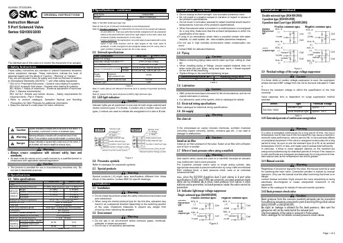
Instruction Manual5 Port Solenoid Valve Plug-in Type Series SY3000/5000/7000The intended use of this valve is to control the movement of an actuator.These safety instructions are intended to prevent hazardous situations and/or equipment damage. These instructions indicate the level of potential hazard with the labels of “Caution,” “Warning” or “Danger.”They are all important notes for safety and must be followed in addition to International Standards (ISO/IEC) *1), and other safety regulations. *1)ISO 4414: Pneumatic fluid power - - General rules relating to systems.ISO 4413: Hydraulic fluid power - - General rules relating to systems.IEC 60204-1: Safety of machinery - -Electrical equipment of machines. (Part 1: General requirements)ISO 10218-1: Robots and robotic devices - Safety requirements for industrial robots - Part 1: Robots.• Refer to product catalogues, Operation Manual and Handling Precautions for SMC Products for additional information.Warning•Always ensure compliancewith relevantsafetylaws andstandards.All work must be carried out in a safe manner by a qualified person in compliance with applicable national regulations.Caution• The product is provided for use in manufacturing industries only. Do not use in residential premises.2.1 Manifold specifications *See section3.2, environment, for mounting and operating environment restrictions for metal seal type. Note 1) See section 3.18Note 2) 5Hz or less for power saving circuit type.Note 3) Impact resistance: No malfunction occurred when it was tested with a drop tester in the axial direction and at right angles to the main valve & armature; in both energized & de-energised states and for every time in each condition. (Values at the initial period.)Vibration resistance: No malfunction occurred in a one-sweep test between 45 and 2000 Hz. Tests are performed at both energized and de-energized states in the axial direction and at right angles to the main valve & armature. (Values at the initial period).Note 1) Due to the internal circuit in S/Z type and T type (power saving circuit), the allowable voltage fluctuation should be within the following:S/Z type 24 VDC: –7% to +10% T type 24 VDC: –8% to +10% 12 VDC: –4% to +10% 12 VDC: –6% to +10%Note 2) Valve state is not defined if electrical input is outside the specified operating range.2.4 Special productsWarningSpecial products (-X) might have specifications different from those shown in this section. Contact SMC for specific drawings. 2.5 Pneumatic symbolsRefer to catalogue for pneumatic symbols.3 Installation3.1 InstallationWarning• Do not install the product unless the safety instructions have been read and understood.• When using double solenoid type for the first time, actuators may travel in an unexpected direction depending on the switching position of the valve. Implement countermeasures to avoid any danger that may occur due to the actuator’s operation. 3.2 EnvironmentWarning• Do not use in an environment where corrosive gases, chemicals, salt water or steam are present.• Do not use in an explosive atmosphere.• Do not expose to direct sunlight. Use a suitable protective cover.• Do not install in a location subject to vibration or impact. Check the product specifications.• Do not mount in a location exposed to radiant heat.• Products with IP65 and IP67 enclosures (based on IEC60529) are protected against dust and water; however, these products cannot be used in water.• Products compliant to IP65 and IP67 satisfy the specifications by mounting the product appropriately. Be sure to read the Specific Product Precautions for each product.• When using built-in silencer type manifold with an IP65 or IP67 enclosure, keep the exhaust port of the silencer from coming in directcontact with water or other liquids.• The metal seal valve is provided with a hole to discharge the pilot EXH. When using in atmospheres containing water and dust, mount horizontally.• Do not use in high humidity environment where condensation can occur.• If using in an atmosphere where there is possible contact with water drop-lets, oil, weld spatter, etc., take suitable preventive measures. • When the solenoid valve is mounted in a control panel or it is energized for a long time, make sure that the ambient temperature is within the specification of the valve. •Contact SMC for altitude limitations.3.3 PipingCaution• Before piping make sure to clean up chips, cutting oil, dust etc.• When installing piping or fittings, ensure sealant material does not enter inside the port. When using seal tape, leave 1 thread exposed on the end of the pipe/fitting.• Tighten fittings to the specified tightening torque.3.4 LubricationCaution• SMC products have been lubricated for life at manufacture, and do not require lubrication in service.• If a lubricant is used in the system, refer to catalogue for details. 3.5 One-touch fittings3.5.1 Tube attachment and detachmentCautionRefer to the Specific Precautions in the catalogue.3.6 Precautions on other tube brandsCautionWhen using non-SMC brand tubes, refer to the Specific Precautions in the catalogue.3.7 Indicator Light/Surge Voltage SuppressorIf a valve type without suppression is used, suppression should be provided as close as possible to the valve by the host controller. 3.8 Polarity Surge voltage suppressor (□S)Surge voltage suppressor (□S)Positive common Double solenoid, 3-position, 4-position Negative common Double solenoid, 3-position, 4-positionSurge voltage suppressor (□S)Surge voltage suppressor (□NS)Figure 13.8.2 Non-polar typeWith surge voltage suppressor (□R)Single solenoidDouble solenoidORIGINAL INSTRUCTIONSPolarity protection diodePolarity protection diodePolarity protection diodePolarity protection diodePolarity protection diodePolarity protection diodePolarity protection diodePolarity protection diodeCoil CoilCoil CoilCoil CoilCoilCoil Coil CoilCoilCoilCoilCoilVaristorVaristorVaristor(Green) (Green) (Orange)(Orange)Figure 23.9 With power saving circuitPower consumption is decreased by approximately 1/3rd by reducingthe wattage required to hold the valve in an energized state.(Effective energizing time is over 67 ms at 24 VDC).*Be careful of the energizing time, as quick response and high pressuretypes will become operational when the energizing time is over 40 ms.Standard High pressureFigure 3•The above circuit reduces the power consumption for holding in orderto save energy. Refer to the catalogue for details.•The 12 VDC specification with power saving circuit (standardspecification) does not have the polarity protection diode. Do notmake a mistake with the polarity.•Since the voltage will drop by approx. 0.5 V due to the transistor, payattention to the allowable voltage fluctuation. (For details, refer to thesolenoid specifications of each type of valve.)3.10 Residual VoltageCaution•If a varistor or diode surge voltage suppressor is used, thesuppressor arrests the back EMF voltage from the coil to the levelindicated in Table 7. Ensure the transient voltage is within thespecification of the host controller.•Valve response time is dependent on surge suppression method3.11 Countermeasure for surge voltageCautionAt times of sudden interruption of the power supply, the energy storedin a large inductive device may cause non-polar type valves in a de-energised state to switch.When installing a breaker circuit to isolate the power, consider a valvewith polarity (with polarity protection diode), or install a surge absorptiondiode across the output of the breaker.WarningIf a valve is energized continuously for a long period of time, the rise intemperature due to heating-up of the coil assembly may cause adecline in solenoid valve performance, reduce service life, or haveadverse effects on peripheral equipment.If the valve is energized continuously for a long period of time, be sureto use a valve with power saving circuit. In particular, if three or moreadjacent stations on the manifold are energized simultaneously forextended periods of time or if the valves on A side and B side areenergized simultaneously for a long period of time, take special care asthe temperature rise will be greater.3.13 Momentary energizationCautionIf a double solenoid valve will be operated with momentary energization,it should be energized for at least 0.1 second. However, depending onthe secondary load conditions, it should be energized until the cylinderreaches the stroke end position, as there is a possibility of malfunctionotherwise.3.14 Light IndicationWhen equipped with indicator light and surge voltage suppressor, thelight window turns orange when solenoid ‘a’ is energized, and it turnsgreen when solenoid ‘b’ is energized.Figure 43.15 Valve MountingCaution•Mount the valve so that there is no slippage or deformation in gaskets•Refer to catalogue for other screw torque values.3.16 Manual overrideWarningRegardless of an electric signal for the valve, the manual override isused for switching the main valve. Connected actuator is started bymanual operation. Only use the manual override after confirming thatthere is no danger.WarningLocked manual overrides might prevent the valve responding to beingelectrically de-energised or cause unexpected movement in theequipment.Refer to the catalogue for details of manual override operation.3.17 Changing Connector Entry DirectionCautionRefer to the Specific Product Precautions in the catalogue.3.18 Reverse flowCautionOnly the external pilot variants are suitable for reverse flow withpressure supplied on ports 3 and 5 provided the pressure is less than0.7 MPa. Reverse flow cannot be applied to 'H' variants with built incheck-valves or valves fitted with SY#0M-24-1A check valves.3.19 Back pressure check valvesBack pressure from the common manifold exhausts can be preventedfrom affecting actuators connected to ports 2 and 4 by using the ‘H’variant valve or fitting SY#0M-24-1A check valves.The flow capacity of the valve is reduced in these cases.See catalogue for full details on back pressure check valves.3.20 Effect of back pressure when using a manifoldWarningUse caution when valves are used on a manifold, because an actuatormay malfunction due to back-pressure.For 3-position exhaust centre valve or single acting cylinder, takeappropriate measures to prevent malfunction by using it with anindividual EXH interface block or an individual exhaust manifold.3.21 External pilot exhaustsCautionThe external pilot variants use the manifold PE connection for pilotexhaust. Ensure that this connection is always vented to atmosphereand not subject to any pressure pulses from other devices.3.22 Change of piping types between Top and Side, port blockwhile mounted on a manifold and one-touch fittingsCautionRefer to the Specific Product Precautions in the catalogue.3.23 One-touch FittingsCautionWhen fittings are used, they may interfere with one another dependingon their types and sizes. Therefore, the dimensions of the fittings to beused should first be confirmed in their respective catalogues.4 How to Order4.1 Standard productsRefer to catalogu e for ‘How to order’ information.4.2 Special productsFor special products (-X number) refer to product drawing for ‘How toorder’ details and specifications.5 Outline Dimensions (mm)Refer to the catalogue for outline dimensions.6 Maintenance6.1 General MaintenanceCaution•Not following proper maintenance procedures could cause theproduct to malfunction and lead to equipment damage.•If handled improperly, compressed air can be dangerous.Maintenance of pneumatic systems should be performed only byqualified personnel.•Before performing maintenance, turn off the power supply and besure to cut off the supply pressure. Confirm that the air is released toatmosphere.•After installation and maintenance, apply operating pressure andpower to the equipment and perform appropriate functional andleakage tests to make sure the equipment is installed correctly.•If any electrical connections are disturbed during maintenance,ensure they are reconnected correctly and safety checks are carriedout as required to ensure continued compliance with applicablenational regulations.•Do not make any modification to the product.•Do not disassemble the product, unless required by installation ormaintenance instructions.•When the 3-position closed centre type is in its rest position, air canbe trapped between the valve and the cylinder. Exhaust this airpressure before removing piping or performing any maintenance.•When the equipment is operated after remounting or replacement,first confirm that measures are in place to prevent lurching ofactuators, etc. Then, confirm that the equipment is operatingnormally.•Operate the valve at least once every 30 days.6.2 Supply airWarningUse clean airIf the compressed air supply includes chemicals, synthetic materials(including organic solvents), salinity, corrosive gas etc., it can lead todamage or malfunction.CautionInstall an air filterInstall an air filter upstream of the valve. Filtration degree should be5μm or less.7 Limitations of UseWarningThe system designer should determine the effect of the possible failuremodes of the product on the system.7.1 Limited warranty and Disclaimer/Compliance RequirementsRefer to Handling Precautions for SMC Products.7.2 Holding of pressureSince valves are subject to air leakage, they cannot be used forapplications such as holding pressure (including vacuum) in a system.7.3 Cannot be used as an emergency shut-off valveThis product is not designed for safety applications such as anemergency shut-off valve. If the valves are used in this type of system,other reliable safety assurance measures should be adopted.7.4 Mounting orientationRefer to Section 2.2, table 4 and Section 3.2.7.5 Intermediate stoppingRefer to Handling Precautions for 3/4/5 port Solenoid Valves.Caution7.6 Leakage voltageEnsure that any leakage current when the switching element is OFFcauses ≤3% of the rated voltage across the valve.7.7 Low temperature operationUnless otherwise indicated in the specifications for each valve,operation is possible to -10˚C, but appropriate measures should betaken to avoid solidification or freezing of drainage and moisture, etc.7.8 Air returned or air/spring returned spool valvesWarning•The use of 2-position single valves with air returned or air/springreturned spools has to be carefully considered.•The return of the valve spool into the de-energized position dependson the pilot pressure. If the pilot pressure drops below the specifiedoperating pressure the position of the spool cannot be defined.•The design of the system must take into account such behaviour.•Additional measures might be necessary. For example, theinstallation of an additional air tank to maintain the pilot pressure.Such measures must be evaluated by risk assessment within the7.9 Safety relays or PLCWarningIf a safe output from a safety relay or PLC is used to operate this valve,ensure that any output test pulse duration is shorter than 1 ms to avoidthe valve solenoid responding.8 Product DisposalThis product shall not be disposed of as municipal waste. Check yourlocal regulations and guidelines to dispose this product correctly, inorder to reduce the impact on human health and the environment.9 ContactsRefer to or www.smc.eu for your localdistributer/importer.URL : https:// (Global) https:// www.smc.eu (Europe)SMC Corporation, 4-14-1, Sotokanda, Chiyoda-ku, Tokyo 101 0021, JapanSpecifications are subject to change without prior notice from the manufacturer.© 2021 SMC Corporation All Rights Reserved.Template DKP50047-F-085FPolarity protection diodePolarity protection diodeNot available for the 12 VDCspecificationElectric circuit diagram(with power saving circuit)In the case of single solenoidI1: Starting current, i2: Holding currentSolenoid aSolenoid bLightA side: OrangeB side: GreenCoilCoilCoilVaristorVaristorVaristor。
气动阀门的使用方法说明书使用方法说明书1. 引言气动阀门是一种常见的工业设备,广泛应用于流体控制系统中。
本使用方法说明书旨在向用户提供关于气动阀门的正确使用方法和操作指南,以确保阀门的正常运行和安全性。
2. 产品概述气动阀门是一种通过气压控制的自动化装置,能够在流体管道中实现流体的开启、关闭、调节和分配等功能。
它由阀体、阀盖、阀座、阀芯、活塞和气动执行器等组成。
3. 安全注意事项在使用气动阀门之前,请务必仔细阅读并遵守以下安全注意事项:3.1 确保阀门安装和维护时遵循相关安全规定和操作规程。
3.2 在操作过程中,避免过高的气压,以免对阀门和管道造成损坏或危险。
3.3 切勿将阀门用于超出其设计能力的工况,以免引发事故或损坏设备。
3.4 定期检查阀门和执行器的工作状态,如有异常及时维修或更换。
3.5 在操作阀门时,注意防止冲击、振动和异物进入阀门,以免影响其正常工作。
3.6 使用气动阀门时,请佩戴个人防护装备,确保人身安全。
4. 阀门安装与调试4.1 安装阀门前,请先确保工作区域干燥、清洁,避免灰尘和杂物进入阀门。
4.2 根据阀门的连接方式,正确选择管道和法兰,并确保连接紧固牢固。
4.3 安装完毕后,进行泄漏测试,检查管道和法兰连接处是否存在泄漏现象。
4.4 阀门调试前,请检查气源压力和电源电压是否符合阀门的工作要求。
4.5 在调试阀门时,使用适当的工具和设备,并按照阀门调节指示进行操作。
4.6 调试完成后,测试阀门的开启、关闭和调节功能,并确保阀门工作正常。
5. 阀门操作与维护5.1 操作阀门前,请确保气源处于正常状态,并确认气源压力符合阀门的工作要求。
5.2 气动阀门操作时,请遵循阀门的启闭顺序和操作规程,确保操作正确、平稳。
5.3 在长时间不使用阀门时,应及时关闭气源并进行定期维护保养,以延长阀门寿命。
5.4 阀门的定期维护包括清洁阀门表面、检查法兰连接处的紧固情况、润滑曲轴套等。
5.5 如发现阀门有异常现象,如泄漏、卡阻、无法闭合等,应及时停止使用,并寻求专业维修人员的帮助。
文件No.VM*-OMP0001-A延时阀VR21101.安全注意事项2~82.用途93.规格 94.型式表示方法 95.动作样式106.特性10~117.外形尺寸图 12安全注意事项此处所示的注意事项是为了确保您能安全正确地使用本产品,预先防止对您和他人造成危害和伤害而制定的。
这些注意事项,按照危害和损伤的大小及紧急程度分为「注意」「警告」「危险」三个等级。
无论哪个等级都是与安全相关的重要内容,所以除了遵守国际标准(ISO/IEC)、日本工业标准(JIS)*1)以及其他安全法规*2)外,这些内容也请务必遵守。
*1) ISO 4414: Pneumatic fluid power -- General rules relating to systemsISO 4413: Hydraulic fluid power -- General rules relating to systemsIEC 60204-1: Safety of machinery -- Electrical equipment of machines (Part 1: General requirements)ISO 10218: Manipulating industrial robots-SafetyJIS B 8370: 空气压系统通则JIS B 8361: 油压系统通则JIS B 9960-1: 机械类的安全性‐机械的电气装置(第1部: 一般要求事项)JIS B 8433: 产业用操作机器人-安全性等*2) 劳动安全卫生法等注意误操作时,有人员受伤的风险,以及物品破损的风险。
警告误操作时,有人员受到重大伤害甚至死亡的风险。
危险在紧迫的危险状态下,如不回避会有人员受到重大伤害甚至死亡的风险。
安全注意事项保证以及免责事项/适合用途的条件本产品适用于下述“保证以及免责事项”、“适合用途的条件”。
请在确认、允许下述内容的基础上,使用本公司产品。
文件No.VQZ100V-OMT0001电磁阀VQZ系列(先导阀V100搭载)安全注意事项 -------------------------------------------------------------------------------------- 2,3设计注意事项--------------------------------------------------------------------------------------4,5选定---------------------------------------------------------------------------------------------------4,5安装--------------------------------------------------------------------------------------------------6配管-------------------------------------------------------------------------------------------------6配线--------------------------------------------------------------------------------------------------6给油--------------------------------------------------------------------------------------------------6空气源--------------------------------------------------------------------------------------------------7使用环境-----------------------------------------------------------------------------------------------7维修保养-----------------------------------------------------------------------------------------------7产品个别注意事项-----------------------------------------------------------------------------------8~14故障与对策方法-----------------------------------------------------------------------------------15,16安全注意此处所示的注意事项是为了确保您能安这些注意事项,按照危害和损伤的大小都是与安全相关的重要内容,所以除了外,这些内容也请务必遵守。*1) ISO 4414: Pneumatic fluid power ISO 4413: Hydraulic fluid power IEC 60204-1: Safety of machinery ISO 10218-1992: Manipulating indus JIS B 8370: 空气压系统通则 JIS B 8361: 油压系统通则JIS B 9960-1: 机械类的安全性、机械 JIS B 8433-1993: 产业用操作机器人*2) 劳动安全卫生法 等注意注意误操作时, 警告警告 误操作时,危险危险在紧迫的危险①本产品的适合性请由系统设计者或规因为本产品的使用条件多样化,所以析和试验进行判断。
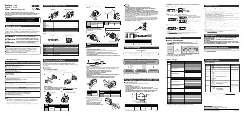
Piping for the One-touch fitting•Insert the tube all the way into the fittingso that it cannot be pulled out.•Insertion with excessive force can cause damage.•Ensure there is no leakage after piping.•Use the product within the specified operating pressure and temperature range.TroubleshootingSpecifications / DimensionsRefer to the product catalogue or operation manual from SMC website(URL ) for more information about the product specifications anddimensions.Note: Specifications are subject to change without prior notice and any obligation on the part of the manufacturer.© 2011-2015 SMC Corporation All Rights ReservedAkihabara UDX 15F, 4-14-1, Sotokanda, Chiyoda-ku, Tokyo 101-0021, JAPANPhone: +81 3-5207-8249 Fax: +81 3-5298-5362URL Refer to the operation manual from SMC website (URL ) for moreinformation about troubleshooting.Function SettingPress the S buttonfor 2 secondsor longer.Press the S button once in measurement mode.[P_1] or [n_1] and [the current set value] are displayed in turn.in turnS∗: For models with switch outputs for both OUT1 and OUT2, [P_2] or [n_2] will be displayed too.Set as above.∗: If a mode other than Hysteresis Mode is selected, refer to the operation manual from SMC website(URL ) or contact SMC.∗: Note that the set value and hysteresis settings are limited by each other.<Operation>(The illustration shows PFMB7201, when not using the reversed display function.)Press the △or ▽button to change the set value.The △button is to increase and the ▽button is to decrease the set value.Press the△button continuouslyto keep increasing the set value.Press the S button to complete the setting.Return to measurement mode.S∗2: This setting is only available for models with switch outputs for both OUT1 and OUT2.∗3: This setting is only available for models with the external input.∗4: This setting is only available for models with the analogue output.Peak/Bottom value displayThe maximum (minimum) flow from when the power was supplied to this moment isdetected and updated. In peak/bottom display mode, the maximum (minimum) flow isdisplayed•For peak display, when the △button is pressed for 1 second or longer,[the maximum flow] and [Hi] are displayed in turn.To release holding the display of the maximum flow, press the △button for 1 second orlonger again to return to measurement mode.•For bottom display, when the ▽button is pressed for 1 second or longer,[the minimum flow] and [Lo] are displayed in turn.To release holding the display of the minimum flow, press the ▽button for 1 second orlonger again to return to measurement mode.If the △and ▽buttons are pressed simultaneously for 1 second or longer while the flowvalue is being held, the peak (bottom) values are reset.Reset operationThe accumulated flow value can be reset, when displaying the accumlated flow.The reset the accumulated flow, press the △and ▽buttons simultaneously for1 second or longer.The peak/bottom value can be reset, when displaying the peak value (bottom value).To reset the peak/bottom value, press the △and ▽buttons simultaneously for 1 secondor longer.Key lock functionTo use each of these functions, refer to the operation manual from SMC website(URL ) or contact SMC.MaintenanceTo change setting, refer to the operation manual from SMC website(URL ) or contact SMC.12321Safety InstructionsMounting•Never mount the product in a place where it will be used as a mechanical support.•Mount the product so that the fluid flows in the direction indicated by the arrow on the sideof the body.Safety InstructionsMounting and InstallationThese safety instructions are intended to prevent hazardous situations and/orequipment damage.These instructions indicate the level of potential hazard with the labels of"Caution", "Warning" or "Danger". They are all important notes for safety and mustbe followed in addition to International standards (ISO/IEC) and other safetyregulations.InstallationPanel mounting (Only PFMB7201)•Refer to the diagram and table below for mounting details.•Refer to the dimension from SMC website (URL )for panelthickness and panel mount cut-out dimensions.OperatorBodyPFMB7201PFMB7501/7102/7202DisplayPFMB7201PFMB7501/7102/7202Bracket mounting•Refer to the diagram and table below for mounting details.•Refer to the dimension from SMC website (URL )for bracketthickness and mounting hole dimensions.Connecting/Disconnecting•When mounting the connector, insert it straight into the socket, holding the lever andconnector body, and push the connector until the lever hooks into the housing, and locks.+ 2 1-1234Power is supplied∗: The outputs will continue to operate during setting.∗: If a button operation is not performed for 30 seconds during the setting, the display will flash.(This is to prevent the setting from remaining incomplete if, for instance, an operator were to leave during setting)∗: 3 step setting mode and Function selection mode are reflected on each other.Flow Setting (set value only) of OUT1 · OUT2Flow[L/min][H_1]Switch ONSwitch OFFSet value[P_1]Outline of settingsDIN rail mounting (Only PFMB7201)•Refer to the diagram and table below formounting details.3 step setting modeIn this mode, only the set values can be input, in just 3 steps.∗: When the reversed display is used, the function of the△and▽buttons is reversed.Piping•Never mount the product upside down.•The straight piping length shall be 8 cm or longer.Otherwise, if a straight section of piping is not installed, the accuracy varies byapproximately ±2%F.S.•Avoid sudden changes in the piping size on the IN side of the product.•Do not release the OUT side piping port of the product directly to the atmospherewithout the piping connected.If the product is used with the piping port released to atmosphere, the accuracy may vary.Piping for the metal attachment•Tighten to the specified torque. Refer to the table below for the required torque values.•Use a suitable spanner for the appropriate torque. Do not use a spanner 40 cm orlonger.•If the tightening torque is exceeded, the product can be broken.If the tightening torque is insufficient, the fitting may become loose.•Avoid any sealing tape getting inside the flow path.•Ensure there is no leakage after piping.•When mounting the fitting, a spanner should be used on the metal part (attachment) ofthe fitting only.Holding other parts of the product with a spanner may damage the product.Specifically, make sure that the spanner does not damage the connector.Direct mounting•Refer to the diagram and table below for mounting details.•Refer to the dimension from SMC website (URL )for mountinghole size.Thank you for purchasing an SMC PFMB7 series Digital Flow Switch.Please read this manual carefully before operating the product and make sure youunderstand its capabilities and limitations. Please keep this manual handy forfuture reference.Before UseDigital Flow SwitchPFMB7201/7501/7102/7202Connector pin numbers (lead wire)Press the▽button continuouslyto keep decreasing the set value.PF※※-OMP0003-AHow to reset the product after a power cut or when the power has beenunexpectedly removedThe settings of the product are retained from before the power cut orde-energizing.The output condition also recovers to that before power cut or de-energizing, butmay change depending on the operating environment. Therefore, check the safetyof the whole installation before operating the product.settingsdefault settings are shown below.When the flow exceeds the set value [P_1], the switch will be turned ON.When the flow falls below the set value by the amount of hysteresis [H_1] or more, theswitch will turn OFF.If the operation shown in the diagram below is acceptable, then keep these settings.For more detailed settings, set each function in the function selection mode.Default settingsWiringConnection•Connections should only be made with the power supply turned off.•Use a separate route for the product wiring and any power or high voltage wiring.Otherwise, malfunction may result due to noise.•Ensure that the FG terminal is connected to ground when using a commerciallyavailable switch-mode power supply. When a switch-mode power supply is connectedto the product, switching noise will be superimposed and the product specification canno longer be met. This can be prevented by inserting a noise filter, such as a line noisefilter and ferrite core, between the switch-mode power supply and the product or byusing a series power supply instead of a switch-mode power supply.Error indicationNOTEThe direct current power supply used should be UL approved as follows.Circuit (class 2) of maximum 30 Vrms (42.4 V peak) or less, with UL 1310class 2 power supply unit or UL 1585 class 2 transformer.The product is a UL approved product only if it has a mark on the body.Function selection modeIn measurement mode, press the S button for 2 seconds or longer, to display [F 0].The [F] indicates the mode for changing each Function Setting.Press the S button for 2 seconds or longer in function selection mode to return tomeasurement mode.。
文件No.SY3000∗-OMH0002电磁阀SY系列(搭载V100先导阀)安全上的注意事项 --------------------------------------------------------------------------------------2,3设计上的注意事项-------------------------------------------------------------------------------------- 4,5选定---------------------------------------------------------------------------------------------------------4,5安装-------------------------------------------------------------------------------------------------------- 6配管-------------------------------------------------------------------------------------------------------- 6配线-------------------------------------------------------------------------------------------------------- 6润滑-------------------------------------------------------------------------------------------------------- 6气源--------------------------------------------------------------------------------------------------------7使用环境-----------------------------------------------------------------------------------------------7维护点检-----------------------------------------------------------------------------------------------7产品个别注意事项---------------------------------------------------------------------------------------- 8~14 故障及应对方法 -------------------------------------------------------------------------------------------15,16安全上的注意事项这里所指注意事项,记载了产品应如何正确安全的使用,以防止对您及他人造成损伤。
3 p o r t d i r e c t a c t i n g v a l v e1063M3PA*M3PB*Note 1: Effective sectional area S and sonic conductance C are converted as S 5.0 C. 10643 p o r t d i r e c t a c t i n g v a l v e1065500 mm 1000 mm 2000 mm 3000 mmSeries variation3PA/3PB SeriesLead wire (11/0.16)1066Electric connection circuit diagram3PA/3PB Series3 p o r t d i r e c t a c t i n g v a l v e1067Pneumatic componentsSafety precautionsAlways read this section before starting use.Refer to Intro 63 for valve general precautions.3 port direct acting valve pneumatic valve 3PA/3PB SeriesThe application differs from the solenoid valve for maintaining the vacuum. When using a pad, set a filter between the pad and valve so that foreign matter does not enter.Do not use this as a solenoid valve for emergency shut down.If left pressurized for a long time, the starting response could be delayed.When using with a vacuum, select direct current (DC) specifications.Install a vacuum filter on the suction port.CAUTIONEnergizing for a long time could impair solenoid valve performance.Similar caution is required in the following use.· During intermittent energizing, it takes longer than non-energizing.· During intermittent energizing, one energizing session exceeds 30 min.Consider heat dissipating measures when installing.Consult with CKD when using this device in a continuous energizing state.During Use & MaintenanceCAUTIONThe surge suppressor enclosed with the solenoid valve is to protect the output contact for that solenoid valve's drive. There is no significant protection for the other peripheral devices, and devices could be damaged or malfunction by the surge. Surge generated by other devices could be absorbed and cause damage such as burning. Care must be taken for points below.(1) The surge suppressor functions to limit a solenoid valve surge voltage, which can reach several hundred V, to a low voltage level that the output contact can withstand. Depending on the output circuit used, this may be insufficient and could result in damage or malfunction. Check whether the surge suppressor can be used by the surge voltage limit of the solenoid valve in use, the output device's withstand pressure and circuit structure, and by the degree of return delay time.If necessary, provide other surge measures. The inverse voltage surge generated when OFF can be suppressed to the following levels.(2) When using the NPN type output unit, the voltage given in the left table and a surge voltage equivalent to the power voltage could be applied on the output transistor. Increase the contact protection circuits in this case.(3) If another device or solenoid valve is connected in parallel to the solenoid valve, the inverse voltage surge generated when the valve is OFF would apply to those devices. Even when using the solenoid valve with surge suppressor for 24 VDC, the surge voltage may reach minus several ten V depending on the model. This inverse polarity voltage could damage or cause the other devices connected in parallel to malfunction. Avoid parallel connection of devices susceptible to reversing polarity voltages, e.g., LED indicators.When driving several solenoid valves in parallel, the surge from other solenoid valves could enter the surge suppressor of one solenoid valve with a surge suppressor. Depending on the current value, that surge suppressor could burn.When driving several solenoid valves with surge suppressors in parallel, surge current could concentrate at the surge suppressor with the lowest limit voltage and cause similar burning. Even if the solenoid valve type is the same, the surge suppressor's limit voltage can be inconsistent, and in the worst case, could result in burning. Avoid driving several solenoid valves in parallel.(4) The surge suppressor incorporated in the solenoid valve often short-circuits if damaged by overvoltage or overcurrent from a source other than the solenoid valve. If the surge suppressor fails, if a large current flows when output is on, the output circuit or solenoid valve could be damaged or ignite. Do not keep power on in a faulty state.Provide an overcurrent protection circuit on the power or drive circuit or use a power supply with overcurrent protection so that alarge current does not flow continuously.(Example of output transistor protective circuit installation 1)(Example of output transistor protective circuit installation 2)Programmable controller sideSolenoid valve sideProgrammable controller sideSolenoid valve side1068D i s c r e t e 3 p o r t d i r e c t a c t i n g v a l v e10693PA/3PB SeriesDiscrete valveHow to order discrete valve10703PA SeriesDiscrete valve: Body portingInternal structure and parts list 2-position single solenoid 3PA1103PA210Repair parts listMain parts list Operational principle3P Series is a pressure balance poppet valve which is not effected by working pressure. This valve maintains large flow rale but low wattage consumption.Port can be pressurized from either 1, 2 or 3 port.The diameters of valve seat and packing seal of stem assembly are same. Since pressure differentials of each port are stabilized by through hole of stem assembly, pressure is well balanced during ON and OFF.When de-energizedThe stem assembly is pushed toward port 1 side by the plunger spring force transmitted by the plunger.Valve seat and packing seal of stem assembly close port 1, while open port 2 and 3.*Port No. 1, 2, 3 indicates; Port 1: P, NC Port 2: A, COM Port 3: R, NO23131*3: Precautions apply when assembling the coil assembly into thevalve. Contact CKD for information.D i s c r e t e 3 p o r t d i r e c t a c t i n g v a l v e10713PB SeriesDiscrete valve: Sub-plate portingInternal structure and parts list2-position single solenoid3PB1103PB210When energizedWhen energizing the coil, the plunger is absorbed toward the coil side, while the stem assembly is moved by the stem spring force. This opens port 1 and 2, but closes port 3.*Port No. 1, 2, 3 indicates; Port 1: P, NC Port 2: A, COM Port 3: R, NO23 1313PA110-M53PA1/3PA2 Series2-position single solenoid: Grommet lead wire Mounting plate: (P) 3PA210-062-position single solenoid: Grommet lead wire Mounting plate: (P)1072D i s c r e t e 3 p o r t d i r e c t a c t i n g v a l v e1073Discrete valve: Body portingDimensionsø4, ø6 push-in joint: (GS4, GS6)3PA1C-connector: (C, C1, C2, C3) D-connector: (D, D1, D2, D3) Locking manual override: (M1)3PA1/3PA2 SeriesTerminal box: (B)Terminal box: (B, L, LS)Terminal box with indicator light: (L, L2, LS)C-connector: (C, C1, C2, C3)D-connector: (D, D1, D2, D3)Locking manual override: (M1)ø4, ø6 push-in joint: (GS6, GS8)3PA2(ø6 push-in joint)10743PB110-063PB1/3PB2 Series2-position single solenoid: Grommet lead wire3PB210-06 082-position single solenoid: Grommet lead wireD i s c r e t e 3 p o r t d i r e c t a c t i n g v a l v e1075Discrete valve: Sub-plate portingDimensionsTerminal box: (B)3PB13PB2C-connector: (C, C1, C2, C3) D-connector: (D, D1, D2, D3)Locking manual override: (M1)C-connector: (C, C1, C2, C3)D-connector: (D, D1, D2, D3)Locking manual override: (M1)3PB1/3PB2 SeriesTerminal box with indicator light: (L, L2, LS)Terminal box: (B, L, LS)Note 2: Response time is the value when ON for supply pressure 0.5 MPa, pre-lubricated. The value varies depending on pressure and quality of lubricant.1076I n d i v i d u a l w i r i n g m a n i f o l d 3 p o r t d i r e c t a c t i n g v a l v e1077M3PA/M3PB SeriesIndividual wiring manifold* Gasket, set screw attachedM3PA/M3PB SeriesIndividual wiring manifoldHow to order individual wiring manifoldHow to order masking plate kit* Gasket and set screw attached5S1MP 2Indicate the quantity.How to order mixed manifold models(1) Indicate the quantity for each function (solenoid position) at the end of the model.Functions and symbols are indicated below.(2) Indicate the function (solenoid position) and layout position in the remarks field.Example: 2-position single solenoid –› S1Example: S1 = 1 to 5 (1 to 5th station is 2-position single solenoid.)2-position single solenoid (S1): 5 piece (1 to 5th station)Masking plate: 2 piece (6, 7th station)M3PB180-06-M1-B-7-3<Example of model number>For 7 stationSolenoid position symbol = , th station (facing the piping port, the left side is the 1st station.)LayoutSymbolS1 = 1 to 5 MP = 6 to 75S1MP2How to order mix manifold5S1MP2S1 = 1 to 5, MP = 6 to 71079M3PA/M3PB SeriesIndividual wiring manifoldI n d i v i d u a l w i r i n g m a n i f o l d 3 p o r t d i r e c t a c t i n g v a l v e1080M3PA180-M5M3PA1/M3PA2 SeriesPort 2 - Individual piping Port 1, 3 - Common porting: Grommet lead wireM3PA280-06Port 2 - Individual piping Port 1, 3 - Common porting: Grommet lead wire3PA119-M5-[Option]-[Voltage]Model no. of discrete solenoid valve for manifold 3PA219-06-[Option]-[Voltage]Individual wiring manifold: Body porting DimensionsM3PA1C-connector: (C, C1, C2, C3) D-connector: (D, D1, D2, D3) Locking manual override: (M1)M3PA1/M3PA2 SeriesTerminal box: (B)Terminal box with indicator light: (L, L2, LS)ø4, ø6 push-in joint: (GS4, GS6)C-connector: (C, C1, C2, C3) D-connector: (D, D1, D2, D3) Locking manual override: (M1)ø6, ø8 push-in joint: (GS6, GS8) Terminal box: (B, L, LS)M3PA2Individualwiringmanifold3portdirectactingvalve10811082M3PB180-06M3PB1 SeriesPort 2 - Individual piping Port 1, 3 - Common porting: Grommet lead wireM3PB180-06APort 2, 3 - Individual piping Port 1 - Common porting: Grommet lead wireModel no. of discrete solenoid valve for manifold 3PB119-00-[Option]-[Voltage]1083Individual wiring manifold: Sub-plate portingDimensionsM3PB1C-connector: (C, C1, C2, C3)D-connector: (D, D1, D2, D3)Locking manual override: (M1)M3PB1 SeriesTerminal box: (B)Terminal box with indicator light: (L, L2, LS)M3PB180-06BPort 1, 2 - Individual piping Port 3 - Common porting: Grommet lead wireø4, ø6 push-in joint: (GS4, GS6)I n d i v i d u a l w i r i n g m a n i f o l d 3 p o r t d i r e c t a c t i n g v a l v e1084M3PB280-06M3PB2 SeriesPort 2 - Individual piping Port 1, 3 - Common porting: Grommet lead wireM3PB280-06YPort 2 - Back porting Port 1, 3 - Common portingM3PB280-06APort 2, 3 - Individual piping Port 1 - Common porting: Grommet lead wireModel no. of discrete solenoid valve for manifold 3PB219-00-[Option]-[Voltage]Model no. of discrete solenoid valve for manifold 3PB219-00-[Option]-[Voltage]JIS symbolJIS symbol1085Individual wiring manifold: Sub-plate portingDimensionsM3PB2C-connector: (C, C1, C2, C3)D-connector: (D, D1, D2, D3)Locking manual override: (M1)M3PB2 SeriesTerminal box: (B, L, LS)M3PB280-06BPort 1, 2 - Individual piping Port 3 - Common porting: Grommet lead wireø6, ø8 push-in joint: (GS6, GS8)I n d i v i d u a l w i r i n g m a n i f o l d 3 p o r t d i r e c t a c t i n g v a l v e10862°3PA/3PB SeriesTechnical data (1) How to wire terminal box wiring and connectorHow to wire terminal box wiring and connectorRefer to the following drawing, and wire the terminal boxfollowing steps 1) to 3) below.1) Pass the cap (4), washer (5), and gasket (6) in order through the cabtire cable (7), and insert in case (2).2) When using a crimp terminal, treat the cabtire cable (7) at an appropriate length as shown in the figure, and crimp the crimp terminal (8) onto the end.3) Remove screw (10) from terminal gland (3), and pass through crimp terminal (8). (When using the Y type terminal, loosen and sandwich the terminal.) Then, tighten screw (10) again. Note: Tighten at torque of 0.5 N·m ±15%.Remarks: Bare wires can be wired. In this case, loosen screw (10), andinsert leads into the fitting, then tighten again.The cord’s direction can be changed by pulling the gland out of the case, rotating it 180°, then pressing it into the case again.The following crimp terminals (8) can be used.Use equivalent products when using other brands.3 p o r t d i r e c t a c t i n g v a l v e1087O.D. ø4 to 6.5Tighten the lead wire with the set screw.A small flat-tipped screwdriver is required.23( )Note: Do not tighten together with thesurge suppressor.Insert the gasket andterminal block into the voltage terminal and grounding terminal.Technical data (1) How to wire terminal box wiring and connector3PA/3PB SeriesPower consumption 1.8 W becomes 2.0 W when the 24 VDC light is enclosed.。
产品名称:SMC中文说明书
SMCCORPORATION成立于1959年,总部设在日本东京都。
时至今日,SMC已成为世界级的气动元件研发、制造、销售商。
在日本本土更拥有庞大的市场网络,为客户提供产品及售后服务。
SMC 作为世界最著名的气动元件制造和销售的跨国公司,其销售网及生产基地遍布世界。
SMC产品以其品种齐全、可靠性高、经济耐用、能满足众多领域不同用户的需求而闻名于世。
在日本市场占有率已超过60%的SMC,通过分布于世界51个国家的海外子公司及分销商,将世界各国SMC产品的生产、销售连成一体,为用户提供直接、完善的服务。
SM-14S M C系列阀门电动装置使 用 说 明 书天津百利二通机械有限公司TIANJIN BAILI ERTONG MACHINERY CO.,LTD.目 录第一部分 SMC系列普通型产品使用说明第二部分 SMC系列整体型产品使用说明第三部分 SMC系列隔爆型产品使用说明第四部分 SMC-04~SMC-2低温型产品使用说明第一部分 SMC系列普通型产品使用说明1.概述SMC系列多回转型阀门电动装置(以下称电动装置)用于驱动控制阀瓣作直线运动的闸阀、截止阀、隔膜阀等多回转阀门。
SMC系列中的部分机座产品也可以同BA伞齿轮减速器或直齿轮减速器组合,形成SMC/BA等组合式多回转电动装置。
当SMC系列产品与HBC蜗轮减速器或JA行星减速器组合后则成为组合式部分回转电动装置,它用于驱动控制阀瓣作旋转运动的球阀、蝶阀、旋塞阀等部分回转阀门。
SMC系列电动装置可以远距离电动操作(控制室内操作),可以根据订货要求加装现场按钮灯盒,从而具备现场操作功能。
SMC系列产品的手动机构可完成现场手动操作阀门。
由于SMC/BA、SMC/HBC、SMC/JA等组合型式电动装置的控制、调节部件均在SMC系列产品上,所以本说明书同样适用于上述产品。
(图1)~(图9)所示为SMC、SMC/BA、SMC/HBC、SMC/JA普通型产品的外形主视图。
上述产品的外形和法兰连接尺寸可参见我公司有关产品样本。
所用电动装置的输出转矩、转速、转圈数、电动机功率等详见该电动装置的铭牌。
2.基本技术参数产品符合GB/T24923-2010《普通型阀门电动装置技术条件》2.1动力电源:380V、50Hz(特殊订货可提供220V、415 V、440 V、460 V、480 V、660 V、690 V,50Hz、60Hz)三项正弦交流电(根据用户要求,某些规格可提供单相220V电源的电动机)。
2.2外壳保护等级:IP65~IP67(IP68订货时提出)2.3使用环境温度:-20℃~70℃(根据用户订货要求)2.4环境相对湿度:≤90%(25℃时)2.5海拔高度:≤1000m2.6短时工作:时间定额为10、15、30min(根据电动机负载情况而定)2.7无强烈振动工况。