丰田卡罗拉_电路部件说明
- 格式:pdf
- 大小:23.30 KB
- 文档页数:2
——转向信号和危险警告灯 (107)——照明、尾灯 (111)——车内照明灯 (119)——前雾灯 (125)——后雾灯 (128)——自动灯光控制、车灯自动熄灭系统 (132)——钥匙提醒(不带智能进入和起动系统) (135)——前刮水器和清洗器 (139)——ABS、TRC、VSC (141)——SRS (150)——换档锁止 (156)——座椅安全带警告 (157)——座椅加热器 (161)——门锁控制 (163)——无线门锁控制(不带智能进入和起动系统) (169)——防盗 (175)——电动车窗 (180)——滑动天窗 (185)——EPS (189)——遥控后视镜(不带卷收器) (193)——遥控后视镜(带卷收器) (195)——喇叭 (197)——点烟器 (198)——电动座椅 (199)——音响系统、后视野监视系统、导航系统 (201)——组合仪表(不带TFT显示屏) (208)——组合仪表(带TFT显示屏) (217)——冷却风扇 (226)——PTC加热器(带手动空调)、手动空调 (231)——PTC加热器(带自动空调)、自动空调 (237)——车灯提醒器 (243)——后窗除雾器、后视镜加热器 (247)——时钟 (250)——接地点 (251)九、插接器表 (259)如何使用本手册 B 本手册将车辆上安装的电路按所属系统划分,提供各系统电路的资料。
各系统电路的实际配线是指从蓄电池开始的电源点到各搭铁点的配线。
(所有电路图均显示所有开关关闭时的状态。
)对任何故障进行故障排除时,首先要了解故障电路的工作原理 (参见“系统电路”一章),了解对此电路供电电源的工作原理 (参见“电源”一章) 和搭铁点的工作原理 (参见“搭铁点”一章),同时还可参见“系统概述”来了解电路的工作原理。
了解电路原理后,可以开始对故障电路进行故障排除,找出故障原因。
利用“继电器位置分布图”和“电路图”来找出各个零件、接线盒和线束连接器、线束和线束连接器及系统电路的搭铁点。
丰田卡罗拉_电路使用说明2丰田卡罗拉_电路使用说明2本文是关于丰田卡罗拉电路使用说明的详细解释,包括了车辆的电路结构、电路元件的功能、常见故障及其排查方法等内容。
通过本文的阅读,您将对丰田卡罗拉的电路系统有更深入的了解,能够更好地使用和维护您的爱车。
一、电路结构1.动力电路:包括发动机、传动系统、燃油系统等与动力相关的电路。
2.照明电路:包括前照灯、尾灯、转向灯等车辆照明系统的电路。
3.仪表电路:包括仪表盘、指示灯、警示灯等仪表系统的电路。
4.供电电路:包括电瓶、发电机、点火系统等供电设备的电路。
5.控制电路:包括故障诊断、电子控制单元等控制系统的电路。
二、电路元件及其功能1.电瓶:负责存储电能并提供起动电流。
2.发电机:通过转动发电机产生电流,为电瓶充电。
3.点火系统:提供火花点火能量,启动发动机。
4.开关:控制电路的开关,如车门开关、点火开关等。
5.传感器:感知车辆状态并将信号转换为电信号,如氧气传感器、轮速传感器等。
6.电控单元:根据传感器的信号控制相关设备,如发动机控制单元、空调控制单元等。
7.继电器:将小电流信号转换为大电流信号,用于控制高功率设备,如大灯继电器、雨刷继电器等。
三、常见故障及排查方法1.车辆无法点火:故障可能原因:点火开关损坏、电瓶电量不足、发电机故障。
排查方法:首先检查点火开关是否正常工作,如有必要更换开关。
然后检查电瓶电量,如电量不足,需充电或更换电瓶。
最后检查发电机正常工作,如有问题,需修理或更换发电机。
2.灯光不亮:故障可能原因:灯泡损坏、继电器故障、电路断开。
排查方法:首先检查灯泡是否损坏,如有必要更换灯泡。
然后检查继电器是否正常工作,如有问题,需修理或更换继电器。
最后检查电路是否有断开的地方,如有断开,需修复电路连接。
3.指示灯故障:故障可能原因:仪表盘故障、传感器故障、电控单元故障。
排查方法:首先检查仪表盘是否有损坏,如有必要更换仪表盘。
然后检查传感器是否正常工作,如有问题,需修理或更换传感器。
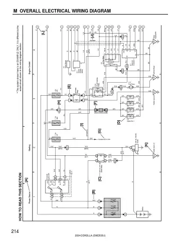
M OVERALL ELECTRICAL WIRING DIAGRAM2142004 COROLLA (EWD533U)2004 COROLLA (EWD533U) 215[A]:System Title[B]:Indicates the wiring color.Wire colors are indicated by an alphabetical code.B=Black W=White BR=BrownL=Blue V=Violet SB=Sky BlueR=Red G=Green LG=Light GreenP=Pink Y=Yellow GR=GrayO=OrangeThe first letter indicates the basic wire color and thesecond letter indicates the color of the stripe.Example: L – Y(Blue)(Yellow)[C]:The position of the parts is the same as shown inthe wiring diagram and wire routing.[D]:Indicates the pin number of the connector.The numbering system is different for femaleand male connectors.Example :Numbered in orderfrom upper left tolower rightNumbered in orderfrom upper right tolower leftFemale MaleThe numbering system for the overall wiring diagram isthe same as above[E]:Indicates a Relay Block. No shading is used andonly the Relay Block No. is shown to distinguishit from the J/B.[F]:Junction Block (The number in the circle is the J/B No.and the connector code is shown beside it).Junction Blocks are shaded to clearly separate themfrom other parts.3C indicates thatit is insideJunction BlockNo.3Example:[G]:Indicates related system.[H]:Indicates the wiring harness and wiring harnessconnector. The wiring harness with maleterminal is shown with arrows ( ).Outside numerals are pin numbers.[I]:( ) is used to indicate different wiring andconnector, etc. when the vehicle model, engine type,or specification is different.[J]:Indicates a shielded cable.[K]:Indicates and located on ground point.[L]:The same code occuring on the next page indicatesthat the wire harness is continuous.M2004 COROLLA (EWD533U)216SYSTEMS LOCATION SYSTEMS LOCATIONABS12–2. . . . . . . . . . . . . . . . . . . . . . . . . . . . . . . . . . . . . . . . . . . . . . . . . . . . .Air Conditioning26–2. . . . . . . . . . . . . . . . . . . . . . . . . . . . . . . . . . . . . . . . . . .Automatic Glare–Resistant EC Mirror with Compass14–4. . . . . . . . . . .Back–Up Light10–8. . . . . . . . . . . . . . . . . . . . . . . . . . . . . . . . . . . . . . . . . . . .Charging2–2. . . . . . . . . . . . . . . . . . . . . . . . . . . . . . . . . . . . . . . . . . . . . . . . . . .Cigarette Lighter21–2. . . . . . . . . . . . . . . . . . . . . . . . . . . . . . . . . . . . . . . . . . .Clock21–2. . . . . . . . . . . . . . . . . . . . . . . . . . . . . . . . . . . . . . . . . . . . . . . . . . . .Combination Meter24–2. . . . . . . . . . . . . . . . . . . . . . . . . . . . . . . . . . . . . . . .Cruise Control11–2. . . . . . . . . . . . . . . . . . . . . . . . . . . . . . . . . . . . . . . . . . . . . .Door Lock Control15–2. . . . . . . . . . . . . . . . . . . . . . . . . . . . . . . . . . . . . . . . .Electronically Controlled Transmission10–2. . . . . . . . . . . . . . . . . . . . . . . .Engine Control3–2. . . . . . . . . . . . . . . . . . . . . . . . . . . . . . . . . . . . . . . . . . . . . .Fog Light4–8. . . . . . . . . . . . . . . . . . . . . . . . . . . . . . . . . . . . . . . . . . . . . . . . . . .Headlight4–3. . . . . . . . . . . . . . . . . . . . . . . . . . . . . . . . . . . . . . . . . . . . . . . . . . .Heater27–2. . . . . . . . . . . . . . . . . . . . . . . . . . . . . . . . . . . . . . . . . . . . . . . . . . .Horn21–4. . . . . . . . . . . . . . . . . . . . . . . . . . . . . . . . . . . . . . . . . . . . . . . . . . . . .Ignition1–3. . . . . . . . . . . . . . . . . . . . . . . . . . . . . . . . . . . . . . . . . . . . . . . . . . . . .Illumination8–2. . . . . . . . . . . . . . . . . . . . . . . . . . . . . . . . . . . . . . . . . . . . . . . . .Interior Light9–2. . . . . . . . . . . . . . . . . . . . . . . . . . . . . . . . . . . . . . . . . . . . . . . .Key Reminder Buzzer19–4. . . . . . . . . . . . . . . . . . . . . . . . . . . . . . . . . . . . . .Light Reminder Buzzer19–3. . . . . . . . . . . . . . . . . . . . . . . . . . . . . . . . . . . . .Moon Roof18–3. . . . . . . . . . . . . . . . . . . . . . . . . . . . . . . . . . . . . . . . . . . . . . .Power Outlet21–3. . . . . . . . . . . . . . . . . . . . . . . . . . . . . . . . . . . . . . . . . . . . . .Power Source1~27–1. . . . . . . . . . . . . . . . . . . . . . . . . . . . . . . . . . . . . . . . . . .Power Window17–2. . . . . . . . . . . . . . . . . . . . . . . . . . . . . . . . . . . . . . . . . . . .Radiator Fan25–3. . . . . . . . . . . . . . . . . . . . . . . . . . . . . . . . . . . . . . . . . . . . . .Radio and Player23–2. . . . . . . . . . . . . . . . . . . . . . . . . . . . . . . . . . . . . . . . . .Rear Window Defogger22–2. . . . . . . . . . . . . . . . . . . . . . . . . . . . . . . . . . . . .Remote Control Mirror20–2. . . . . . . . . . . . . . . . . . . . . . . . . . . . . . . . . . . . . .Seat Belt Warning19–2. . . . . . . . . . . . . . . . . . . . . . . . . . . . . . . . . . . . . . . . .Shift Lock18–4. . . . . . . . . . . . . . . . . . . . . . . . . . . . . . . . . . . . . . . . . . . . . . . .SRS13–2. . . . . . . . . . . . . . . . . . . . . . . . . . . . . . . . . . . . . . . . . . . . . . . . . . . . .Starting1–2. . . . . . . . . . . . . . . . . . . . . . . . . . . . . . . . . . . . . . . . . . . . . . . . . . . .Stop Light7–2. . . . . . . . . . . . . . . . . . . . . . . . . . . . . . . . . . . . . . . . . . . . . . . . . .Taillight6–2. . . . . . . . . . . . . . . . . . . . . . . . . . . . . . . . . . . . . . . . . . . . . . . . . . . . .Turn Signal and Hazard Warning Light5–2. . . . . . . . . . . . . . . . . . . . . . . . . .TVIP System16–2. . . . . . . . . . . . . . . . . . . . . . . . . . . . . . . . . . . . . . . . . . . . .Wiper and Washer14–2. . . . . . . . . . . . . . . . . . . . . . . . . . . . . . . . . . . . . . . . .Wireless Door Lock Control15–8. . . . . . . . . . . . . . . . . . . . . . . . . . . . . . . . .SYSTEM INDEX M OVERALL ELECTRICAL WIRING DIAGRAM。
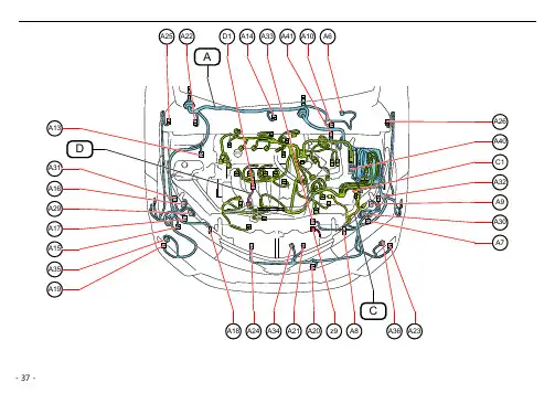

[发动机室]-18-[仪表板]-19-[车身]车门控制接收器 (*1)智能车门控制接收器总成 (*2)燃油泵控制 ECU 总成滑动天窗控制ECU(滑动天窗主动齿轮分总成)* 1: 带智能进入和起动系统* 2: 不带智能进入和起动系统-20-天线-21--22-[发动机室继电器盒和发动机室接线盒内部电路](接下页)120A ALT1250A HTR 1250A ABS NO.11240A RDI1230A ABS NO.21250A DEF 1210A S-HORN 1210A DRL12*11240A H-LP-MAIN1215A EFI-B 1225A EFI-MAIN 1220A STRG LOCK1215A IG21210A TURN&HAZ 1210A ETCS1230A ST 1210A HORN 1230A D/C CUT1211120A RADIO127.5A DOME 1210A ECU-B NO.1121111111111111111111111B11H11E 11G* 1:60A EPS (1ZR-FE, 4ZR-FE) 80A EPS (2ZR-FE, 7ZR-FE)-23-(接上页)7.5A AM21210A ECU-B NO.2125A ECU-B NO.31211111111(接下页)11D 10A H-LP LH-LO1212110A H-LP RH-LO121110A H-LP LH-HI12110A H-LP RH-HI1110A EFI NO.212110A EFI NO.1121110A MIR HTR1230A PTC HTR NO.31230A PTC HTR NO.21230A PTC HTR NO.11211111-24-[发动机室继电器盒和发动机室接线盒内部电路]EFI- MAIN 继电器5 13 21 111 DIM 继电器52311 111 IG2 继电器52311 111 DRL 继电器52311 111 1 号 ST 继电器52311 11 11 11 11 111 541321 111 H-LP 继电器52311 111(接上页)(接下页)DEF 继电器1-25-1 号 FAN 继电器5 23 11 111 2 号 PTC 继电器51321 111 1 号 PTC 继电器51321 111 3 号 PTC 继电器51321 111 EPS 继电器51321 111 HORN 继电器52311 111(接上页)-26-31323334352530292827782423222120919181017161115125613555414535251504948464544434241403938373665432147263132333435253029282778242322212091918101716111512561355541453525150494846454443424140393837366543214726109413211121314151617181920272829303132333435363738394041484950515253545556564221432244237845244625472610941321112131415161718192027282930313233343536373839404148495051525354555656422143224423784524462547261187413291011121314151617182223242526272829303132333435364041424344454647485637193820392187413291011121314151617182223242526272829303132333435364041424344454647485637193820392165413278910111213141516171819202122232425262728293031323334353637383940654132789101112131415161718192021222324252627282930313233343536373839403E3A3D3C2130A POWER2130A P-SEAT 3B(自发动机室主线束)(自仪表板线束)(自仪表板线束)(自地板线束)白色白色白色白色白色(自发动机室主线束)-27-32313029282726252423222120191817主车身 ECU 16151413121110987654321[仪表板接线盒总成内部电路]5A AM1121212127.5A STOP1230A P-SEAT 1220A S/ROOF10A TAIL 7.5A PANELTAIL 继电器FOG RR 继电器13B 553A 283C 273C 43D 123A 133A 473A 483D 93A 273A103E 233D 93D 353C7.5A RR FOG12403E 523C7.5A OBD12127.5A FR FOG33C223D 103D 73A473D 83A 173E 323E233E 283A 103A 243E 483A 493A453A 413D 533C 453D 463D 333E 363A 363D 373D 263E(接下页)W I P F R 25A 12W A S H E R 15A 12R L D O O R 20A 12R R D O O R 20A 12F R D O O R 20A 12D O O R B A C K 10A 12E C U -I G N O .37.5A 12A M 15A 12F R F O G 7.5A 12D /L N O .220A 12S /R O O F 20A 12S T O P 7.5A 12R R F O G 7.5A 12O B D 7.5A 12A /B 7.5A 21M E T 5A 21S E A T H T R 15A 12I G N 7.5A 21E C U -I G N O .55A 12E C U -I G N O .47.5A 12H T R -I G 7.5A 12E C U -I G N O .27.5A 12E C U -I G N O .17.5A 12W I P -S 5A 21P A N E L 7.5A 12T A I L 10A 12S F T L O C K -A C C 5A 12A C C 7.5A 12C I G 15A 12D/LOCK继电器D/UNLOCK 继电器LUG LOCK 继电器133C 143C 83E53C 13E 43C 93E123C23E 393E23A 53E 323C 343C 333C 443A 333D 173D 343D 353D 183D63C183A 393A 383D 193D 203D 83D 1220A D/L NO.21210A DOOR BACK(接下页)(接上页)[仪表板接线盒总成内部电路]253D 243D53D153D323D143D203A313D133D33E383A173A163D373A283E443D423D273D503A283D153A313A433D293D523A513A193C163A383C183C393C7.5A ACC121212121215A CIG63D125A SFTLOCK-ACCACC 继电器263D7.5A HTR-IG7.5A ECU-IG NO.37.5A ECU-IG NO.1127.5A ECU-IG NO.21 号 IG1 继电器(接下页)(接上页)193A 413A 403A 393D 213D 303E 463C 483C 243C 493C263C 473C 93C 563C 123D 43A 33A63A 103C 33D13D 303D3C 113D 13A 23D163C173C 373C 63E 73E13C 1173C 213A 203C 333E 53A 413C 423A553C121212127.5A A/B73D113A125A WIP-S7.5A IGN 5A MET5A ECU-IG NO.51225A WIP FR 43E 23C1215A WASHER1215A SEAT HTR 127.5A ECU-IG NO.43 号 IG1 继电器POWER 继电器2 号 IG1 继电器1230A POWER 1220A RL DOOR 1220A RR DOOR 1220A FR DOOR(接下页)(接上页)(*1)(*2)* 1 : 带防夹功能* 2: 不带防夹功能[仪表板接线盒总成内部电路]4132120528181622FFGO BCTL DIM FLCYILE LSRLGCY HORNDBKL SH LIN2PKBGND1ACT+TRLY ACT-RFGOACCLGYL3HRLY1511814TR+69271029主车身 ECU543A 383E 433C 463A 253E 543C 343E 223E 373E 243A 363E 223C 293E 12143E 403D 353A 443C 423C 213C403C 233C 363C 153C 21563A 273E BECUIG DRLE30293C 433A 163E 313C 503C 303C 153E 313E 24453C 32513C 19353E26533A 17(接上页)4:4 号继电器盒仪表板加强件5533221235115321DOME CUT 继电器HTR 继电器FOG FR 继电器S-HORN 继电器[4 号 R/B 内部电路]523151325231532144444444HTR 继电器S-HORN 继电器4444FOG FR 继电器4444DOME CUT 继电器4444。