菲特18倍AHD高清机芯规格书
- 格式:doc
- 大小:860.50 KB
- 文档页数:22

e-mail:**************For latest product manuals:FV100/FV100-T Series Installation & Operation Manual on Vortex Shedding Flowmeter &Temperature (optional) TransmitterShop online at User’sGuideCONTENTSSubject Page Specifications (3)Operation (4)Applications (4)Using this Manual (5)Model Plate Examples (5)Name Plate Features...........................................................................5/6 Installation.. (6)Electrical/Wiring/Grounding (7)Wiring Diagrams (7)DC Power Supply Voltage Requirements (8)Configuration/Setup.............................................................................8/9 FV100-T Indicators. (10)Model Codes (10)Pressure Drop Data (10)Cabling.................................................................................................3/ 10 Installation Dimensions........................................................................11/12SpecificationsMaximum operating pressure: 300 PSIG (20 Bar)Minimum operating pressure: See page 6 & 10 (Pressure Drop Charts)Maximum operating temperature (fluid and ambient): 185°F (85ºC), 186°F to 210°F (85ºC to 99ºC) with reduced rating of the solid state relay.Minimum operating temperature (fluid and ambient): 35°F (2ºC).Maximum Flow: Meters may be over ranged, occasionally, up to 125% of capacity without damaging the meter****Output is clamped at 21mA, 6.3% over range, display will indicate up to 125% FS Capacities: 3/4" 25 GPM (95 LPM); 1" 50 GPM (190 LPM); 1 1/2" 100 GPM (380 LPM);2" 200 GPM (750 LPM)Process Connections: NPT femaleWetted Parts: Brass, PVDF & VitonEnclosure Rating: Type 1, 3, 4, 12, & 13, IP65Caution: The unit shall be supplied by a SELV (separated extra-low voltage) source inaccordance with CSA Standard C22.2 No.1010.1-92 Annex H.Display: 3 digit LED digital display, 0.3" highEnvironmental conditions: This device has been designed for use in Installation category I, pollution degree 4, at altitudes up to 2000 meters (6560 ft.), either indoors or outdoors as defined in CSA Standard C22.2 No.1010.1-92.Flow (electrical)Accuracy: ± 5% of Full ScaleAnalog Output: 4-20 mA (600 ohm @ 24 Vdc) proportional to flowResponse Time: 1.5 seconds to 63% of step changeRepeatability: ± 0.25% of actual flowAlarm Output: Low flow, Solid State SPST Relay, rated to 125 mA @ 30 Vdc, up to 185° F,*50 mA @ 30 Vdc between 186° F & 210° F (85-99° C)Alarm Deadband: 5% of full scaleAlarm State:NO or NC above setpoint (selectable)Electrical Connection: 5-pin micro dc male connectorTemperature (electrical)Accuracy: ± 1% of Full ScaleAnalog Output: 4-20 mA (600 ohm @ 24 Vdc); 4 mA= 32° F (0° C) to 20 mA = 212° F (110° C) Response Time: 1.5 seconds to 63% of step changeRepeatability: ± 0.25% of actual temperatureAlarm Output: High temperature, Solid State SPST Relay, rated to 125 mA @ 30 Vdc, up to 185° F, *50 mA @ 30 Vdc between 185° & 210° F (85-99° C)Alarm Deadband: 2% of full scaleAlarm State: Same as selected for FlowOPERATIONFV100 is an inline flow meter that utilizes the vortex shedding principle. The fluid strikes a bluff body generating vortices (eddies) that move downstream. The vortices form alternately, from one side to the other. A piezoelectric sensor housed in a sensor tube directly downstream of the bluff senses the pressure zones created by the vortices. The sensor generates a frequency directly proportional to the vortices (flow). The pulses are then amplified by the circuit board and converted to a 4-20 mA output, which is also linear with flow. Flow can be displayed on the LED display in either GPM or LPM. Selection of the preferred units of measure is made from two white front panel push buttons. There is also a solid state relay output that can be set for a low flow contact from 15% to 90% of full-scale flow. The relay can be configured to be NC (normally closed) or NO (normally open) at flow (above set point). It will change state on decreasing flow upon reaching the setpoint.FV100-T meters combine temperature measurement with the flow measuring features of FV100 Series. The housing utilizes a temperature sensor housed in a small thermowell directly downstream of the flow sensor. FV100-T meters display temperature or flow on the LED display. Temperature can be displayed in either degrees Fahrenheit or Celsius and is selectable from the two white front panel buttons. There is a 4-20 mA output proportional to temperature and a solid state relay that can be configured for a high temperature set point. The relay function will be the same as selected for flow, normally closed or normally open, below set point, since it is a high alarm. So, you have two transmitters in one - flow and temperature.APPLICATIONSFV100/FV100-T can be used on low viscosity clean or dirty water-like liquids that are compatible with brass, PVDF & Viton. Metered fluids should not include long fibers or a significant level of abrasive solids. Bluffs are replaceable, as are the sensors, should abrasive wear occur over time. Typical applica-tions will be for cooling loops using water, 50% solutions of glycols, and water soluble machine coolant (up to 10%). These applications are found in most process industries, including rubber, steel, fabrication, manufacturing, refining, paper, chemical, food, petrochemical and power. They cannot be used on flammable liquids or gases including air.NOTE: If this equipment is used in any manner not specified herein, the protection provided by the equipment may be impaired.Cleaning: These meters do not require any special cleaning of the external surfaces. If cleaning is desired, do not use any strong solvents, detergents, or chemicals. Brushing away accumulations of dirt or wiping with a cloth and water is suggested.USING THIS MANUALTo use this manual, you will require the model code, which can be found on the nameplate of the meter, as shown on the example below. See page 10 for “Model Codes.” The Model Code will allow you to determine the minimum & maximum flow capabilities for each as well as related pressure drops.All FV100 or FV100-T meters are equal in terms of features and functions. The only difference is the flow capacity of the various sizes.MODELPLATE EXAMPLESFEATURES: FV100 SeriesINSTALLATIONThere are no upstream or downstream piping requirements to achieve the operating specifications given herein. The meters may be installed in any position as long as good piping installation requirements are adhered to for best results. This includes proper support of adjacent piping to minimize inherent vibra-tions produced within the system. Unions of the same pipe size and full port isolation ball valves may be installed for ease of removal and servicing of equipment, if required. Meters should be placed in hori-zontal, slightly ascending runs or vertical runs to prevent entrained air from accumulating in the meter. They should not be placed at the highest point in the piping for this same reason. Piping system should be filled slowly to prevent water hammer from damaging sensor. The meter sensor can also be damaged by reverse flow.Isolation ball valves, when used, should be in the full open position. Throttling valves should always be placed downstream of the meter, a minimum of 10 pipe diameters downstream.Teflon®tape or pipe sealant can be used in mounting the meter to the piping when using good technique. Teflon®tape, if not applied properly to the connecting piping, can become caught on the bluff and affect the flow measurement.Use of diaphragm or piston pumps will affect metering performance, unless they are installed with a properly sized pulsation dampener and pressure control valve, to minimize pulsating flow. The piping system must create some backpressure on the meter to allow vortex formation and to prevent cavitation, especially at full flow. Minimum required back pressure is 10 PSIG at max flow and 70° F (21° C). Higher back pressures are required at elevated temperatures and occasional surges to 125% of max flow. This situation will not be encountered in most installations. If while increasing the flow, the signal or displayed flow appears to drop off, but reappears when flow is reduced, contact OMEGA to determine back pressure requirements to extend the flow range to the capacity of the meter.Electrical/Wiring/GroundingElectrical Service: General PurposeElectrical Classification: Non-hazardous Type 1, 2, 3, 4 (equal to IP 65), 12, & 13Power Requirements: 24 VDC (10-30 VDC) @ 80 mAElectrical Connections: 5-Pin micro style for FV100 or 8-Pin micro style for FV100-T, DC Cabling: 5 or 8 Pin DC female shielded cable (do not connect shielding at the panel)Grounding: Note, that DC and Chassis Grounds are internally connected to eliminate electrical noise. If this poses a problem with your control wiring, please contact UFM for an alternative solution.Current Output: 4-20 mA (Note: Use of a 250 Ohm, 0.1%, 1/2 watt precision resistor will produce a 1-5 VDC signal for voltage input receivers)Solid State Relay: Optically isolated, current limited to 125 mA @ 30 VDC up to 185° F (85° C), de-rated to 50 mA @ 30 VDC between 186° & 210° F (86° C to 99° C)WIRING DIAGRAMS (Pin Configurations)DC Power Supply Voltage RequirementsCONFIGURATION (Setup)FV100 comes pre-calibrated and pre-configured in Gallons Per Minute, with the Solid State Relay set for 0 flow, which inactivates the relay. To change the engineering units displayed to LPM, reset the solid state relay for a minimum flow condition, or change the relay function (nc-normally closed or no-normally open) requires a simple reconfiguration. By powering up the meter, it can be reconfigured or checked at the bench or installed position.To configure the FV100 display for GPM or LPM, press the SET button so that the LED next to the desired engineering unit is lit. To configure the set point, or alarm function, hold the MENU button down until the display indicates “flo”, then “AL”, then release it. The LED display will indicate zeros or a set point. Change the setting, by pressing the MENU button. Each time it is pressed, it will step the set point upwards, holding it down will ramp the set point up quickly until the desired set point is ap-proached, then pressing discreetly will step it up to the desired setting. At the highest setting for each meter capacity, it will roll over to 0. Then as the MENU button is pressed it will step or ramp up if held down. Once the desired set point is displayed, use the SET button to enter the value.If no set point is required, then select 0 with the SET button - this will inactivate the relay, as well as the local LED indicator, which flashes on reaching the set point. The two LED indicators that are adjacent to GPM & LPM flash when the flow drops to or below the set point. If GPM has been selected, it will remain on solid and the LPM indicator will flash. The opposite occurs when LPM is the selected unit of measure displayed.CONFIGURATION (Setup) continued...The next parameter, relay function, will automatically appear. It may indicate “nc”, normally closed, or “no”, normally open. Pressing the MENU button will change the relay function from one to the other. To select the desired relay condition, merely press the SET button. The relay function selected is at the normal flow condition, above set point. So, by selecting “no”, the relay will be open above the set point and close on reaching the set point or lower. Conversely, if “nc” is selected, the relay will be closed above the set point and open at or below set point.Once the relay function is set, the meter will return to the run mode. If no flow is present, the meter should display zeros and the LED adjacent to the unit of measure not selected will be flashing to indicate a low flow condition (unless a set point of zero was selected).FV100-T includes the features of FV100 plus temperature. FV100-T has a second set of LED’s adjacent to the SET button. One is labeled F, for degrees Farenheit, and the second C, for degrees Celcius.To setup the flow portion of FV100-T, the flow variable must be displayed. Pressing the MENU button one time, toggles between the displayed variables of flow and temperature. Press the MENU button once if temperature is the displayed variable. Then complete the setup for the flow variable as, described above under FV100.To configure the temperature portion of FV100-T , press the MENU once, if the temperature variable is not displayed. Temperature, since it is being measured on power up, will be displayed as degrees F or C dependent upon the status of the LED indicators adjacent to the two units of measure. To enter a set point, hold the MENU button down until “t”, then “AL” are displayed, consecutively. The display will then indicate the set point. To change, press the MENU button to step the value upward, or hold the MENU button down to quickly ramp up the setting, releasing as the desired value is approached, and then pressing incrementally until the set point is reached. Then press the SET button to enter the se-lected value. Again, as in the flow set point, if the set point is passed, continue holding the MENU button down and it will roll over to zero and continue increasing until released and incremented slowly to the desired value. After selecting the set point the meter will return to the run mode.****NOTE: The relay function for temperature is the same as selected for flow. If the “nc”, normally closed condi-tion is selected for flow, it will also function the same way for temperature. The relay function (status) is always at the normal condition. So, if “nc” is selected, the relay will be closed above the flow set point and below the temperature set point. That is because we are normally looking for a low flow condition and a high temperature condition in cooling applications. When either set point is reached for flow or temperature, its respective relay will change state. The set points, when selected in either GPM or LPM and F or C, will automatically con-vert to the correct value, if the other unit of measure is selected.FV100-T LED IndicatorsThe LED’s adjacent to the engineering units of GPM, LPM, F, & C have two functions. The first is to indicate the process variable being displayed and its respective engineering unit, the second to indicate alarm conditions. If temperature is being displayed, say 75 F, then 75 will appear in the display and the LED adjacent to F will be lit. If the temperature would increase to its respective set point, then the actual value will be displayed, the F LED will remain lit and the LED adjacent to C would begin flashing. If, at the same time, there is a low flow condition, both LED’s next to GPM & LPM will also flash - indicat-ing a flow fault also, so that you can press the MENU button to verify the flow rate.In either case, if flow or temperature is the displayed value, when a fault condition occurs on the nondisplayed value, the two indicator LED’s associated with that variable will both flash to providea local indication of a fault. The solid state relays will still function independently, also regardless of the variable being displayed. As will the 4-20 mA outputs.MODEL CODESInstallation DimensionsInstallation Drawings, 3/4" & 1"INInstallation Drawing, 1 1/2" & 2"INWARRANTY/DISCLAIMEROMEGA ENGINEERING, INC. warrants this unit to be free of defects in materials and workmanship for a period of 13 months from date of purchase. OMEGA’s WARRANTY adds an additional one (1) month grace period to the normal one (1) year product warranty to cover handling and shipping time. This ensures that OMEGA’s customers receive maximum coverage on each product.If the unit malfunctions, it must be returned to the factory for evaluation. OMEGA’s Customer Service Department will issue an Authorized Return (AR) number immediately upon phone or written request. Upon examination by OMEGA, if the unit is found to be defective, it will be repaired or replaced at no charge. OMEGA’s WARRANT Y does not apply to defects resulting from any action of the purchaser, including but not limited to mishandling, improper interfacing, operation outside of design limits, improper repair, or unauthorized modification. T his WARRANT Y is VOID if the unit shows evidence of having been tampered with or shows evidence of having been damaged as a result of excessive corrosion; or current, heat, moisture or vibration; improper specification; misapplication; misuse or other operating conditions outside of OMEGA’s control. Components in which wear is not warranted, include but are not limited to contact points, fuses, and triacs.OMEGA is pleased to offer suggestions on the use of its various products. However, OMEGA neither assumes responsibility for any omissions or errors nor assumes liability for any damages that result from the use of its products in accordance with information provided by OMEGA, either verbal or written. OMEGA warrants only that the parts manufactured by the company will be as specified and free of defects. OMEGA MAKES NO OTHER WARRANTIES OR REPRESENTATIONS OF ANY KIND W HATSOEVER, EXPRESSED OR IMPLIED, EXCEPT THAT OF TITLE, AND ALL IMPLIED WARRANTIES INCLUDING ANY WARRANTY OF MERCHANTABILITY AND FITNESS FOR A PARTICULAR PURPOSE ARE HEREBY DISCLAIMED. LIMITATION OF LIABILITY: The remedies of purchaser set forth herein are exclusive, and the total liability of OMEGA with respect to this order, whether based on contract, warranty, negligence, indemnification, strict liability or otherwise, shall not exceed the purchase price of the component upon which liability is based. In no event shall OMEGA be liable for consequential, incidental or special damages.CONDITIONS: Equipment sold by OMEGA is not intended to be used, nor shall it be used: (1) as a “Basic Component” under 10 CFR 21 (NRC), used in or with any nuclear installation or activity; or (2) in medical applications or used on humans. Should any Product(s) be used in or with any nuclear installation or activity, medical application, used on humans, or misused in any way, OMEGA assumes no responsibility as set forth in our basic WARRANTY/DISCLAIMER language, and, additionally, purchaser will indemnify OMEGA and hold OMEGA harmless from any liability or damage whatsoever arising out of the use of the Product(s) in such a manner.RETURN REQUESTS/INQUIRIESDirect all warranty and repair requests/inquiries to the OMEGA Customer Service Department. BEFORE RET URNING ANY PRODUCT(S) T O OMEGA, PURCHASER MUST OBTAIN AN AUT HORIZED RET URN (AR) NUMBER FROM OMEGA’S CUST OMER SERVICE DEPART MENT (IN ORDER T O AVOID PROCESSING DELAYS). The assigned AR number should then be marked on the outside of the return package and on any correspondence.The purchaser is responsible for shipping charges, freight, insurance and proper packaging to prevent breakage in transit.FOR WARRANTY RETURNS, please have the following information available BEFORE contacting OMEGA:1.Purchase Order number under which the productwas PURCHASED,2.Model and serial number of the product underwarranty, and3.Repair instructions and/or specific problemsrelative to the product.FOR NON-WARRANTY REPAIRS,consult OMEGA for current repair charges. Have the following information available BEFORE contacting OMEGA: 1. Purchase Order number to cover the COSTof the repair,2.Model and serial number of the product, and3.Repair instructions and/or specific problemsrelative to the product.OMEGA’s policy is to make running changes, not model changes, whenever an improvement is possible. This affords our customers the latest in technology and engineering.OMEGA is a registered trademark of OMEGA ENGINEERING, INC.© Copyright 2004 OMEGA ENGINEERING, INC. All rights reserved. T his document may not be copied, photocopied, reproduced, translated, or reduced to any electronic medium or machine-readable form, in whole or in part, without the prior written consent of OMEGA ENGINEERING, INC.Where Do I Find Everything I Need for Process Measurement and Control?OMEGA…Of Course!Shop online at TEMPERATUREⅪߜThermocouple, RTD & Thermistor Probes, Connectors, Panels & AssembliesⅪߜWire: Thermocouple, RTD & ThermistorⅪߜCalibrators & Ice Point ReferencesⅪߜRecorders, Controllers & Process MonitorsⅪߜInfrared PyrometersPRESSURE, STRAIN AND FORCEⅪߜTransducers & Strain GagesⅪߜLoad Cells & Pressure GagesⅪߜDisplacement TransducersⅪߜInstrumentation & AccessoriesFLOW/LEVELⅪߜRotameters, Gas Mass Flowmeters & Flow ComputersⅪߜAir V elocity IndicatorsⅪߜTurbine/Paddlewheel SystemsⅪߜTotalizers & Batch ControllerspH/CONDUCTIVITYⅪߜpH Electrodes, Testers & Accessorie sⅪߜBenchtop/Laboratory MetersⅪߜControllers, Calibrators, Simulators & PumpsⅪߜIndustrial pH & Conductivity EquipmentDA T A ACQUISITIONⅪߜData Acquisition & Engineering SoftwareⅪߜCommunications-Based Acquisition SystemsⅪߜPlug-in Cards for Apple, IBM & CompatiblesⅪߜDatalogging SystemsⅪߜRecorders, Printers & PlottersHEATERSⅪߜHeating CableⅪߜCartridge & Strip HeatersⅪߜImmersion & Band HeatersⅪߜFlexible HeatersⅪߜLaboratory HeatersENVIRONMENTALMONITORING AND CONTROLⅪߜMetering & Control InstrumentationⅪߜRefractometersⅪߜPumps & TubingⅪߜAir, Soil & Water MonitorsⅪߜIndustrial Water & Wastewater TreatmentⅪߜpH, Conductivity & Dissolved Oxygen Instruments。
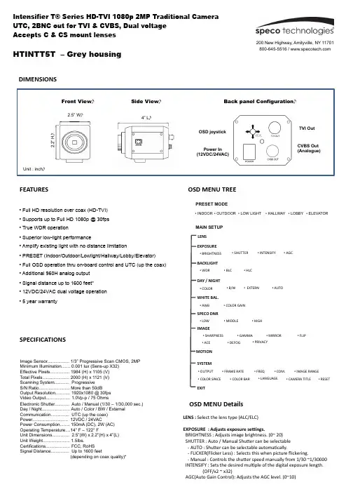
DIMENSIONSFEATURESHTINTT5T – Grey housingSPECIFICATIONSImage Sensor.................. 1/3” Progressive Scan CMOS, 2MP Minimum Illumination....... 0.001 lux (Sens-up X32) Effective Pixels................ 1984 (H) x 1105 (V) Total Pixels...................... 2000 (H) x 1121 (V) Scanning System............ Progressive S/N Ratio......................... More than 50dB Output Resolution............ 1920x1080 @ 30fps Video Output.................... 1.0Vp-p / 75 OhmsElectronic Shutter............ Auto / Manual (1/30 – 1/30,000 sec.) Day / Night....................... Auto / Color / BW / External Communication............... UTC (up the coax) Power............................. 12VDC / 24VACPower Consumption........ 150mA (DC), 2W (AC) Operating Temperature....14° F – 122° FUnit Dimensions.............. 2.5”(W) x 2.2”(H) x 4”(L) Unit Weight...................... 1.5Ibs.Certifications.................... FCC, RoHS Signal Distance............... Up to 1600 feet(depending on coax quality)*• Full HD resolution over coax (HD-TVI) • Supports up to Full HD 1080p @ 30fps • True WDR operation• Superior low-light performance• Amplify existing light with no distance limitation• PRESET (Indoor/Outdoor/Lowlight/Hallway/Lobby/Elevator) • Full OSD operation thru on-board control and UTC (up the coax) • Additional 960H analog output • Signal distance up to 1600 feet* • 12VDC/24VAC dual voltage operation • 5 year warrantyOSD M ENU T REEEXPOSURE• B /W• E XTERN• L OW• M IDDLE• H IGH• S HARPNESS • G AMMA • M IRROR • F LIPDAY / N IGHTWHITE B AL.SPECO D NRIMAGEEXIT• B RIGHTNESS• S HUTTERBACKLIGHT• H LC• B LC• W DR• A UTO• A WB• C OLOR G AIN• A CE• D EFOGSYSTEM• C OM.• I MAGE R ANGE • C OLOR S PACE• F RAME R ATE• I NTENSIFY• A GC• C OLOR• P RIVACYLENS MOTION • O UTPUT • L ANGUAGE• C OLOR B AR• R ESET• C AMERA T ITLE• F REQLENS : S elect t he l ens t ype (ALC/ELC)EXPOSURE : A djusts e xposure s eEngs.B RIGHTNESS : A djusts i mage b rightness. (0~ 20) S HUTTER : A uto / M anual S huTer c an b e s electable -‐ A UTO : S huTer c an b e s electable a utomaVcally.-‐ F LICKER(Flicker L ess) : S elects t his w hen p icture flickering.-‐ M anual : C ontrols t he s huTer s peed m anually f rom 1/30 ~1/30000 I NTENSIFY : S ets t he d esired m ulVple o f t he d igital e xposure l ength. (OFF/x2 ~ x 32)A GC(Auto G ain C ontrol): A djusts t he A GC l evel. (0~10)OSD M ENU D etailsPRESET MODE• INDOOR • OUTDOOR • LOW LIGHT • LOBBY • HALLWAY • ELEVATORMAIN SETUP Side ViewFront ViewBack panel ConfigurationUnit : inchTVI OutCVBS Out (Analogue)Power In (12VDC/24VAC)OSD joystick4” L2.5” W2.2” HSpeco T echnologies i s c onstantly d eveloping p roduct i mprovements. We r eserve t he r ight t o m odify p roduct d esign a nd s pecificaRons w ithout noRce a nd w ithout i ncurring a ny o bligaRon. R ev. 160809OSD M ENU D etailsDAY / N IGHT : A djust D ay / N ight o pRons . C OLOR : A lways C olor m ode. B /W : A lways B /W m ode.-‐ A NTI-‐SAT. : A djusts t he A nV S aturaVon l evel (0~20) E XT : p lease d o n ot u se t his m ode f or t his i temA UTO : D ay / N ight i s s witching a utomaVcally b y A GC l evel. -‐ A NTI-‐SAT. : A djusts t he A nV S aturaVon l evel (0~20) -‐ A GC T HRES : A djusts A GC T HRES (0~20) -‐ A GC M ARGIN : A djusts A GC m argin (0~20)-‐ D ELAY : A djusts t he c hanging d elay V me (LOW/MIDDLE/HIGH)WHITE B AL. : A djusts w hite b alancing o pRons.A WB : i t g oes t o o pVmized c olor l evel a utomaVcally.C OLOR G AIN : S ets t he d esired C olor G ain v alue (0~20)S PECO D NR : U ses t o r educe t he b ackground n oise i n a l ow l uminance e nvironment w ith 2D + 3D filtering s ystem.BACKLIGHT : A djusts b acklight o pRons.W DR : W DR i lluminates d arker a reas o f a n i mage w hile r etaining t hes ame l ight l evel f or b righter a reas t o e ven o ut t he o verall b rightness o f i mages w ith h igh c ontrast b etween b right a nd d ark a rea -‐ A djusts t he W DR W eight (LOW/MIDDLE/HIGH) * C VBS o ut c annot a djust t his f uncVon.B LC : P roduces a c learer i mage o f a n o bject d arkened b y s trong b acklighVng. -‐ H -‐POS : A djusts t he h orizontal p osiVon(0~20) -‐ V -‐POS : A djusts t he V erVcal p osiVon(0~20) -‐ H -‐SIZE : A djusts t he h orizontal b lock s ize (0~20) -‐ V -‐SIZE : A djusts t he v erVcal b lock s ize (0~20)H LC : U ses t o c ontain e xtremely b right a reas s uch a s f rom c ar h eadlight, t he l ight c an b e m asked o ut m uch o f t he o n-‐screen d etails. IMAGE : A djusts v arious i mage o pRons.S HARPNESS: A djusts s harpness l evel. I ncreasing t his v alue, t he p icture o utline b ecomes s tronger a nd c lear. (0~10) G AMMA : S ets t he d esired G amma v alue. (0.45 ~ 0.75) M IRROR : C hange t he v ideo d irecVon h orizontally. F LIP: C hange t he v ideo d irecVon p erpendicularly.A CE (D-‐WDR) : U ses a d igital w ide d ynamic r ange t o b alance d ark a nd o ver s aturated a reas w ithin t he i mage.D EFOG : A cVvated t his m ode w hen t he v ideo o r t he w eather i s f oggy. P RIVACY : U sed t o h ide r egions o f t he i mage. -‐ Z ONE N UM : S elects t he z one n umber u p 15. -‐ Z ONE D ISP : S elects d esired z one w ith O N o r O FF -‐ H -‐POS : A djusts t he h orizontal p osiVon(0~60) -‐ V -‐POS : A djusts t he v erVcal p osiVon(0~40) -‐ H -‐SIZE : A djusts t he h orizontal s ize(0~40) -‐ V -‐SIZE : A djusts t he v erVcal s ize(0~40)-‐ Y -‐LEVEL : A djusts t he y ellow c olor l evel (0~20) -‐ C B L EVEL : A djusts t he b lue c olor l evel (0~20) -‐ C R L EVEL : A djusts t he r ed c olor l evel (0~20)SYSTEM : A djusts v arious c amera s ystem o pRons. O UTPUTF RAME R ATE: S elect t he f rame r ate 30fps/60fps a ccording t o t he v ideooutput m ode. F REQ C OM.-‐ C AM I D : S ets t he c amera I D f or t he R S-‐485 (0~255)-‐ B AUD R ATE : S ets t he b aud r ate f or t he R S-‐485 (2400~115200). I MAGE R ANGE C OLOR S PACEC OLOR B AR : M anufacturer’s o pVonL ANGUAGE : S ets t he d esired O SD l anguage C AMERA T ITLER ESET: P ress w ith l ong t o r eset a ll s elngs t o f actory d efaults.MOTION : A djust m oRon d etecRon s eEngs.-‐ S ENSITIVITY : S ets t he d esired o f “MoVon” (0~20)-‐ W INDOW T ONE : A djusts t he w indow t one v alue (0~60) -‐ W INDOW U SE : A djusts t he w indow s elng s ize (0~3) -‐ W INDOW Z ONE : a cVvate o r d eacVvate m oVon w indow -‐ D ET H -‐POS :Adjusts t he h orizontal p osiVon(0~60) -‐ D ET V -‐POS : A djusts t he v erVcal p osiVon(0~40) -‐ D ET H -‐SIZE : A djusts t he h orizontal s ize(0~60) -‐ D ET V -‐SIZE : A djusts t he v erVcal s ize(0~40) -‐ A LARM : S elect A larm b etween O N o f O FFHTINTT5T – Grey housing。
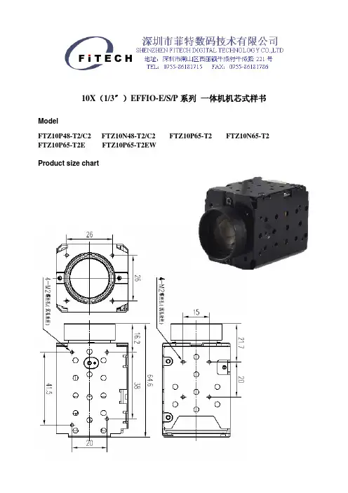
10X(1/3〞)EFFIO-E/S/P系列一体机机芯式样书ModelFTZ10P48-T2/C2 FTZ10N48-T2/C2 FTZ10P65-T2 FTZ10N65-T2 FTZ10P65-T2E FTZ10P65-T2EWProduct size chartSpecificationsZoom CameraFTZ10P65-T2EWFTZ10P65-T2EFTZ10P65Model FTZ10P48700TVL700TVLResolution 480TVL650TVLCommunication mode RS232Signal system PAL/NTSCCCD 1/3" SONY Exview HAD CCD IIEffective pixels 500(H)×582(V) PAL:960(H)×582(V) / NTSC:967(H)×494(V)Day & Night Colour/ B&W /AutoMini.Illumination 0.01Lux(infra LED on)Sync System Inter-syncVideo output CVBS Output (1Vp-p-p75 Ω)SNR ≥48dBLensFNO./Focal Length F/2 f=5mm~5mmIRCUT IRCUTIRCUT OptionalAUTO IRIS ——FOV H:51.8°(W)~5.86°(T)V:39.1°(W)~4.4°(T)M.O.D 0.5m(W)~1m(T)FunctionsOSD Display SupportLens Initialization AutoExposure Mode Auto/ManualAWB Auto/Indoor/Outdoor/Manual Focus Mode Auto/ManualPicture Effects Auto/Color/B&W/NegativeBacklight Compensator SupportContrast Adjust Saturation AdjustMirror Image Support(HOR)Digital Zoom —— SupportSupport Freeze ——Support Rollovers ——WDRDual-scanD-WDRWDR D-WDR2D/3D-DNR DNR 2D-DNRGeneral SpecificationsSize 38.6(W)* 41(H)* 64.6(L) mmWorking Temp./Hygro. ﹣10℃~50℃,10%RH~60%RHStorage Temp./Hygro. ﹣20℃~60℃,10%RH~80%RHPower Voltage DC 12V±10%Power consumption 2.5W MAXNet Weight 100gCommand ListPin assignmentThe Connect Pins Functions Table: the order of 1 to 9 pin location and the following table.cdefghijkPin NO. Name Specificationc RxD CMOS 3.3V (low: max 0.8V, high: min 2.8V) Read Dated TxD CMOS 3.3V (low: max 0.8V, high: min 2.8V) Send Datee GND (for RxD&TxD)f DC IN 12V±3Vg GND (for DC IN)h VBS OUT 1.0V±0.2Vi GND (for VBS OUT)j NCk GNDCommand List(注明:命令中红色标记项为可选项,根据产品型号对应功能。

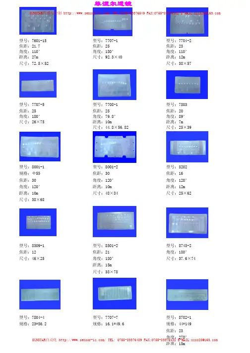
型号:7707-5 型号:7708-1 型号:7803 焦距:25 焦距:25 焦距:20角度:180°角度:79.8°角度:89°尺寸:26×75 距离:10m 距离:7m尺寸:44.8×56.82 尺寸:25×39型号:8001-1 型号:8001-2 型号:8202 规格:Ф55 焦距:30 焦距:16焦距:30 角度:120°角度:120°角度:120°距离:10m 距离:12m距离:10m 尺寸:48×84 尺寸:25×62 尺寸:38×68SUNSTAR自动化/TEL:0755-********FAX:0755-********E-MAIL:**************型号:7707-5 型号:7708-1 型号:7803 焦距:25 焦距:25 焦距:20角度:180°角度:79.8°角度:89°尺寸:26×75 距离:10m 距离:7m尺寸:44.8×56.82 尺寸:25×39型号:8001-1 型号:8001-2 型号:8202 规格:Ф55 焦距:30 焦距:16焦距:30 角度:120°角度:120°角度:120°距离:10m 距离:12m距离:10m 尺寸:48×84 尺寸:25×62 尺寸:38×68型号:7707-5 型号:7708-1 型号:7803 焦距:25 焦距:25 焦距:20角度:180°角度:79.8°角度:89°尺寸:26×75 距离:10m 距离:7m尺寸:44.8×56.82 尺寸:25×39型号:8001-1 型号:8001-2 型号:8202 规格:Ф55 焦距:30 焦距:16焦距:30 角度:120°角度:120°角度:120°距离:10m 距离:12m距离:10m 尺寸:48×84 尺寸:25×62 尺寸:38×68型号:7709-1 型号:7709-2 型号:8202-6焦距:7.6 外径:Ф17 角度:90° 内径:Ф15距离:5m 尺寸:Ф21型号:001 型号:2091 型号:8731-1 外径:Ф55 外径:Ф55 规格:Ф45.2 内径:Ф44内径:Ф44角度:180°距离:10m角度:120°Feinier lens菲涅尔透镜SUNSTAR传感与控制/TEL:0755-********FAX:0755-********E-MAIL:**************SUNSTAR自动化/TEL:0755-********FAX:0755-********E-MAIL:**************SUNSTAR传感与控制/TEL:0755-********FAX:0755-********E-MAIL:**************SUNSTAR商斯达实业集团是集研发、生产、工程、销售、代理经销、技术咨询、信息服务等为一体的高科技企业,是专业高科技电子产品生产厂家,是具有10多年历史的专业电子元器件供应商,是中国最早和最大的仓储式连锁规模经营大型综合电子零部件代理分销商之一,是一家专业代理和分銷世界各大品牌IC 芯片和電子元器件的连锁经营綜合性国际公司。

Philipswidescreen flat TV with Pixel Plus HD26"LCD integrated digital26PFL7532DTurn up your viewing experiencewith Integrated Digital TunerWith this TV you can now enjoy the benefits of digital TV, Electronic Programme Guide and digital quality content. At the same time, you can also watch superb pictures with Pixel Plus HD clarity and details.Vivid, natural and razor sharp images•HD LCD WXGA display, with a 1366 x 768p resolution •Integrated Digital Tuner for DVB-T reception•HD Ready for the highest quality display of HD signals •Pixel Plus HD for better details, depth and clarity•3D combfilter separates colours for a razor-sharp image Exciting and lifelike sound•Incredible Surround™ for enhanced audio enjoyment Slim, stylish design to complement your interior •Compact and slim design that fits in every room Designed for your convenience•1000-page Hypertext for instant fast access to teletext For advanced performance•2 HDMI inputs for full digital HD connection in one cableHighlightsLCD WXGA display, 1366 x 768pThis WXGA display with state-of-the-art LCD screen technology gives you widescreen HD resolution of 1366 x 768p pixels. It produces brilliant flicker-free progressive scan pictures with optimum brightness and superb colours. This vibrant and sharp image will provide you with an enhanced viewing experience. Integrated Digital DVB-T tunerThe integrated DVB-T tuner lets you receive Digital Terrestrial TV to watch or record. This means you do not need an additional set-top box or additional cables.HD ReadyEnjoy the exceptional picture quality of High Definition pictures and be fully prepared for HD sources like HDTV set-top boxes and Blu-ray discs. HD Ready is a protected label that offers picture quality beyond that of progressive scan. It conforms to strict standards laid out by EICTA to offer an HD screen that displays the benefits of the resolution and picture quality of a High Definition signal. It has a universal connection for both analogue YPbPr and uncompressed Digital connection of DVI or HDMI, supporting HDCP. It can display 720p, and 1080i signals at50 and 60 Hz.Pixel Plus HDPixel Plus HD is a picture processingtechnology that enables viewers to watchcontent that is vivid, natural and real. Theresult is superbly razor sharp pictures withincredible details and depth from any HDsource.3D CombfilterThe 3D combfilter separates brightness andcolour signals better in 3D domain to eliminatecross-colour, cross-luminance and dot-crawldistortion - all of which detract from yourviewing pleasure. The 3D digital combfilterperforms field-by-field comparisons of thetelevision image to accurately separate thecolour from the black-and-white informationand remove both horizontally and verticallyhanging dots, as well as dot crawl. The result isa razor sharp image.Incredible Surround™Incredible Surround is an audio technologyfrom Philips that dramatically magnifies thesound field to immerse you in the audio. Usingstate-of-the-art electronic phase shifting,Incredible Surround mixes sounds from leftand right in such a way that it expands thevirtual distance between the two speakers.This wider spread greatly enhances the stereoeffect and creates a more natural sounddimension. Incredible Surround allows you toexperience total surround with greater depthand width of sound, without the use ofadditional speakers.Compact and slim designThis design style emphasises a slim, compactlook that saves space and fits in anywhere.2 HDMI inputsHDMI makes an uncompressed digital RGBconnection from the source to the screen. Byeliminating conversion to an analogue signal, itdelivers an unblemished image. The non-degraded signal reduces flicker and leads to aclearer picture. HDMI intelligentlycommunicates the highest output resolutionwith the source device. The HDMI input is fullybackwards-compatible with DVI sources butincludes digital audio. HDMI uses HDCP copyprotection. With 2 HDMI inputs you canconnect multiple HD sources, for instance anHD set-top box and a Blu-ray player. Your TVis fully prepared for the HD future.Issue date 2011-08-04Version: 4.1.912 NC: 8670 000 26846EAN: 87 12581 31473 6© 2011 Koninklijke Philips Electronics N.V.All Rights reserved.Specifications are subject to change without notice. Trademarks are the property of Koninklijke Philips Electronics N.V. or their respective owners.SpecificationsPicture/Display•Aspect ratio: Widescreen, 16:9•Brightness: 500 cd/m²•Dynamic screen contrast: 4000:1•Response time (typical): 8 ms•Viewing Angle (H / V): 160 / 150 degree •Diagonal screen size: 26 inch / 66 cm•Display screen type: LCD WXGA Active Matrix TFT•Panel resolution: 1366 x 768p•Picture enhancement: Pixel Plus HD, Luminance Transient Improver, Colour TransientImprovement, Dynamic contrast enhancement, Contrast Plus, 3/2 - 2/2 motion pull down, 3D Combfilter, Active Control, Digital NoiseReduction, Jagged Line Suppression, Progressive Scan•Screen enhancement: Anti-Reflection coated screenSupported Display Resolution•Computer formatsResolutionRefresh rate 640 x 480 60, 72, 75, 85 Hz 800 x 600 60, 72, 75, 85 Hz 1024 x 768 60, 70, 75, 85 Hz •Video formats Resolution Refresh rate 480i 60 Hz 480p 60 Hz 576i 50 Hz 576p 50 Hz 720p 50, 60 Hz 1080i 50, 60 Hz 1080p 50, 60 HzSound•Equalizer: 7-bands•Output power (RMS): 2 x 10 W•Sound Enhancement: Auto Volume Leveller, Incredible Surround, Dynamic Bass Enhancement •Sound System: Nicam Stereo, StereoLoudspeakers •Built-in speakers: 2Convenience•Child Protection: Child Lock+Parental Control •Clock: Sleep Timer, Wake-up Clock•Ease of Installation: Auto Programme Naming, Automatic Channel Install (ACI), AutomaticTuning System (ATS), Autostore, Fine Tuning, Plug & Play, Programme Name, Sorting•Ease of Use: Auto Volume Leveller (AVL), Easy toggle Dig/Analogue modes, Programme List, Side Control, Smart Picture, Smart Sound•Electronic Programme Guide: 8-day Electronic Programme Guide •Remote Control: TV•Remote control type: RC2034301/01•Screen Format Adjustments: 4:3, Movie expand 14:9, Movie expand 16:9, Subtitle Zoom, Super Zoom, Widescreen•Picture in Picture: Text dual screen •Teletext: 1000-page Hypertext•Teletext enhancements: 4 favourite pages, Programme information LineTuner/Reception/Transmission•Aerial Input: 75 ohm coaxial (IEC75)•TV system: PAL I, PAL B/G, PAL D/K, SECAM B/G, SECAM D/K, SECAM L/L', DVB COFDM 2K/8K •Video Playback: NTSC, SECAM, PAL •DVB: DVB Terrestrial*•Tuner bands: Hyperband, S-Channel, UHF, VHF •Number of Pre-set Channels: 100•Tuner Display:PLLConnectivity•Ext 1 Scart: Audio L/R, CVBS in/out, RGB•Ext 2 Scart: Audio L/R, CVBS in/out, S-video in •Number of Scarts:2•Ext 3: S-video in, CVBS in, Audio L/R in •Ext 4: YPbPr, Audio L/R in •Ext 5: HDMI •Ext 6: HDMI•Other connections: Headphone out, CommonInterfacePower•Ambient temperature: 5°C to 40°C •Mains power: 220 - 240 V, 50/60 Hz •Power consumption: 120 W•Standby power consumption: < 1 WAccessories•Included Accessories: Tabletop stand, Power cord, Quick start guide, User Manual, Registration card, Warranty certificate, Remote Control, Batteries for remote control•Optional accessories: Floor standDimensions•Colour cabinet: Black cabinet with High Gloss Black deco•Set dimensions (W x H x D): 682 x 472 x 114 mm •Set dimensions with stand (W x H x D): 682 x 537 x 200 mm •Product weight: 12 kg•Product weight (+stand): 15 kg •Box dimensions (W x H x D): 836 x 212 x 592 mm•Weight incl. Packaging: 18 kg•VESA wall mount compatible: 200 x 100 mm。
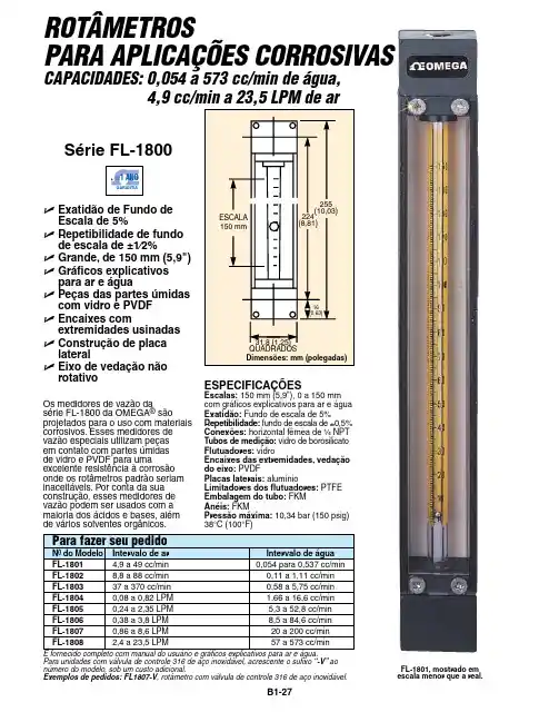
Para unidades com válvula de controle 316 de aço inoxidável, acrescente o sufixo “-V” ao número do modelo, sob um custo adicional.Exemplos de pedidos: FL1807-V , rotâmetro com válvula de controle 316 de aço inoxidável.U E xatidão de Fundo de Escala de 5% U R epetibilidade de fundode escala de ±1⁄2%U G rande, de 150 mm (5,9")U G ráficos explicativospara ar e água U P eças das partes úmidascom vidro e PVDF U E ncaixes comextremidades usinadas U C onstrução de placa lateral U E ixo de vedação nãorotativoOs medidores de vazão da série FL-1800 da OMEGA ® são projetados para o uso com materiais corrosivos. Esses medidores de vazão especiais utilizam peças em contato com partes úmidas de vidro e PVDF para uma excelente resistência à corrosão onde os rotâmetros padrão seriam inaceitáveis. Por conta da sua construção, esses medidores de vazão podem ser usados com a maioria dos ácidos e bases, além de vários solventes orgânicos.FL-1801, mostrado em escala menor que a real.ROTÂMETROS PARA APLICAÇÕES CORROSIVAS CAPACIDADES: 0,054 a 573 cc/min de água,Série FL-1800B1-27ESPECIFICaçõESEscalas:150 mm (5,9"), 0 a 150 mm com gráficos explicativos para ar e água Exatidão:Fundo de escala de 5% Repetibilidade: fundo de escala de ±0,5% Conexões:horizontal fêmea de ¹⁄₄ NPT Tubos de medição: vidro de borosilicato Flutuadores: vidro Encaixes das extremidades, vedação do eixo:PVDF Placas laterais: alumínio Limitadores dos flutuadores: PTFE Embalagem do tubo: FKM anéis: FKMPressão máxima: 10,34 bar (150 psig) 38°C (100°F)。
Série BackBeat FIT 3200 Guide d\'utilisationContenuAperçu des commandes3Alimentation, jumelage et charge4Mise sous tension de l'étui-chargeur4Premier jumelage4Mode de jumelage4Charger4Ajustement et qualité audio6Installer l'application7Principes de base8Mise sous tension et hors tension des écouteurs8Régler le volume8Lire ou mettre en pause du contenu audio8Sélectionner une piste8Faire des appels, répondre et raccrocher9Utilisez Siri et Google Now9Mode DeepSleep9Passez le contrôle pour avoir une meilleure qualité audio9Assistance10Droite Écouteur principal (se jumelle au téléphone)Lecture/pause * Cliquez 1 foisPiste suivante * Cliquez 2 foisPiste précédente * Cliquez 3 foisDécrocher/raccrocher Cliquez 1 foisSiri/Google NOWCliquez et maintenez enfoncé pendant 2 secondes Mise sous tension : Cliquez et maintenez enfoncé pendant 2 secondesMise hors tension : Cliquez et maintenez enfoncé pendant 4 secondesJumelage Alors que les écouteurs sont éteints, cliquez et maintenez enfoncé pendant 4secondesSe reconnecter à l'écouteur gauche Appuyez sur chaque écouteur 3 foisGauche Écouteur secondaire (se connecte à l'écouteur droit)Augmenter le volume Appuyez pour augmenter le volume (bouton tactile)Réduire le volume Touchez et maintenezMise sous tension Cliquez et maintenez enfoncé pendant 2 secondesMise hors tension Cliquez et maintenez enfoncé pendant 4 secondesSe reconnecter à l'écouteur droit Appuyez sur chaque écouteur 3 foisREMARQUE * Cette fonctionnalité varie selon l'application. Elle pourrait ne pas fonctionner avec des applications Web.Aperçu des commandesVotre étui-chargeur est expédié de l’usine dans un mode veille prolongé afin de conserver la charge de la pile. Branchez votre étui-chargeur afin d’alimenter vos écouteurs pour la première utilisation.Cliquez sur le bouton de l'étui-chargeur et maintenez-le enfoncé pendant deux secondes pour l’allumer.Le voyant DEL de l'étui-chargeur s’allume.La première fois que vous retirez les écouteurs de l'étui-chargeur, le processus de jumelage débute.1Retirez les écouteurs de l'étui. Le voyant lumineux situé sur l'écouteur droit clignote en rouge etblanc pour signaler l'activation du mode de jumelage.2Activer la connectivité Bluetooth ® de votre téléphone et lancer la recherche de nouveaux appareils.•iPhone Réglages > Bluetooth > Activé*•Android ™Paramètres > Bluetooth: Activé > Rechercher des appareils*REMARQUE * Le menu peut varier selon l'appareil.3Sélectionnez PLT BBFIT31XX Series Une fois le jumelage réussi, vous entendrez « pairing successful » (jumelage réussi) et le voyant lumineux DEL de l'écouteur arrête de clignoter.Alors que l'écouteur est éteint, cliquez l'écouteur droit et maintenez-le enfoncé jusqu'à ce que vous entendiez « Pairing » (jumelage).Pour charger vos écouteurs, placez-les dans l'étui-chargeur. Chargez l'étui-chargeur en lebranchant à un ordinateur ou à un appareil de charge USB. Pour une recharge plus rapide,branchez-les dans un chargeur mural.Alimentation, jumelage et chargeMise sous tension de l'étui-chargeurPremier jumelageMode de jumelageChargerREMARQUE Si l'étui-chargeur est déchargé, rechargez-le d’abord séparément, puis rechargez ensuite les écouteurs.Recharge des écouteurs ActivéeClignotementsRecharge de l'étui-chargeurÉcouteurs entièrementDésactivéechargésDésactivéeÉtui-chargeurentièrement chargéAjustement et qualité audioPour profiter d'un son optimal, une bonne étanchéité du canal auditif est essentielle. Essayez lestrois tailles d'embouts pour trouver celle qui vous convient le mieux. Vous pourriez vous devoirutiliser des embouts de tailles différentes dans chaque oreille pour créer un ajustementpersonnalisé.Enfoncez l'embout et faites-le pivoter vers la gauche pour le déverrouiller.1Retirer l'embout Array2Replacer l'embout Alignez le nouvel embout et faites-le pivoter vers la droite pour le verrouiller.3Essayez-les Insérez les écouteurs dans vos oreilles et assurez-vous que la boucle de stabilisationest fermement enfoncée dans l'oreille pour en assurer la stabilité.Écoutez votre chanson préférée en essayant les différents embouts et sélectionnez ceux qui vousprocurent le plus de confort et le meilleur son.Installer l'applicationProfitez au maximum de vos écouteurs en installant gratuitement notre application BackBeat pouriOS/Android.Cette application vous permet de :•Avec vos écouteurs (My Tap), écoutez une liste de lecture, utilisez un chronomètre, personnalisezvos paramètres de volume et bien plus encore•Changer la langue des écouteurs•Activer/désactiver les paramètres•Passer le contrôle de l'écouteur droit à l'écouteur gauche•Find MyHeadset•Consulter le guide d'utilisationVous pouvez allumer ou éteindre vos écouteurs manuellement ou automatiquement.•Fonction automatique En retirant les écouteurs de l'étui, ils s’allument automatiquement. Àl’inverse, en les remettant dans l'étui, la mise hors tension est automatique et la charge débute.•Fonction manuelle Cliquez le bouton de l'écouteur et maintenez-le enfoncé pendant 2 secondes pour l’allumer manuellement. Pour le mettre hors tension manuellement, cliquez sur le bouton de l'écouteur et maintenez-le enfoncé pendant quatre secondes.REMARQUE Mettre l'écouteur droit hors tension ferme aussi l'écouteur gauche. Pour les mettre en tension, ouvrez-les individuellement.Transfert d’alimentation Si votre écouteur droit perd l’alimentation, toutes ses fonctions ainsi que l’audio sont transférés àl'écouteur droit.L'écouteur gauche à un bouton tactile. Un léger toucher suffit.1Pour augmenter le volume, appuyer sur l'écouteur gauche.2Pour réduire le volume, touchez et maintenez l'écouteur gauche.Cliquez l'écouteur droit.REMARQUE Cette fonctionnalité varie selon l'application.Double-cliquez l'écouteur droit pour passer à la piste suivante ou triple-cliquez l'écouteur droitpour lire la piste précédente.REMARQUE Cette fonctionnalité varie selon l'application. Elle pourrait ne pas fonctionner avec des applications Web.Principes de baseMise sous tension et hors tension des écouteursRégler le volumeLire ou mettre en pause du contenu audioSélectionner une pisteRépondre ou mettre fin à un appel Cliquez l'écouteur droit.Répondez à un second appel D’abord, cliquez l'écouteur droit pour mettre fin à l'appel en cours, puis cliquez l'écouteur droit de nouveau pour répondre à un nouvel appel.Vos écouteurs prennent en charge les assistants personnels virtuels comme Siri et Google Now.Cliquez et maintenez enfoncé l'écouteur droit pendant deux secondes pour utiliser l'assistant personnel virtuel de votre appareil.Si vous laissez vos écouteurs allumés, mais hors de la portée du téléphone auquel ils sont jumelés pendant plus de 120 minutes, ils se mettent en mode DeepSleep pour conserver la pile, puis s’éteignent après sept jours.Pour sortir du mode DeepSleep, vous avez le choix :•After 120 minutes, allumez chaque écouteur.•Après 7 jours, éteignez et rallumez les écouteurs.Pour avoir la meilleure performance Bluetooth, gardez votre téléphone/appareil audio sur le même côté de votre corps que l'écouteur principal.Votre écouteur droit est l’écouteur principal par défaut. Il se jumelle à votre téléphone/appareil audio, et l'écouteur gauche se connecte automatiquement à l'écouteur droit.Si vous préférez avoir votre téléphone/appareil audio sur le côté gauche de votre corps, utilisez la fonction Intervertir l'écouteur principal dans l’application BackBeat afin de désigner l'écouteur gauche comme écouteur principal. Cela transfert la connexion Bluetooth et les contrôles principaux à l'écouteur gauche, alors que le volume et les contrôles My Tap sont transférés àl'écouteur droit.Faire des appels,répondre et raccrocher Utilisez Siri et Google NowMode DeepSleepPassez le contrôle pour avoir une meilleure qualitéaudioAssistanceBESOIN D'AIDE SUPPLÉMENTAIRE?/supportPlantronics, Inc.Plantronics B.V.345 Encinal Street Santa Cruz, CA 95060 United States Scorpius 171 2132 LR Hoofddorp Netherlands© 2019Plantronics, Inc., BackBeat et Plantronics sont des marques de commerce de Plantronics, Inc., déposées aux États-Unis et dans d'autres pays, et Plantronics Hub est une marque de commerce de Plantronics, Inc. Bluetooth est une marque déposée de Bluetooth SIG, Inc., et Plantronics utilise ces marques sous licence. Les autres marques de commerce sont la propriété de leur détenteur respectif.Brevets en instance.215737-12 (08.19)。
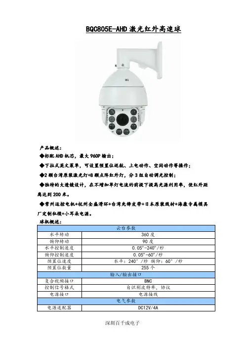
BQC805E-AHD激光红外高速球产品概述:◆标配AHD机芯,最大960P输出;◆下拉式英文菜单,可设置预置位巡航、上电动作、空闲动作等操作;◆2颗台湾原装激光灯+8颗点阵红外灯,分3组自动调光控制;◆独特的大透镜设计,在不增加单灯电流的前提下提高光源利用率,使红外距离达到200米。
◆常州运控电机+杭州全盛滑环+台湾先锋皮带+日本原装线材+海康专属模具厂定制私模+小耳朵电源。
球机概述:云台参数水平转动360度俯仰转动90度水平控制速度0.05º-240º/秒俯仰控制速度0.05º-60º/秒预置位速度水平:240°/秒俯仰:60°/秒预置位数量255个输入/输出接口复合视频接口BNC控制信号格式自识别波特率,协议电源接口电源接线电气参数电源适配器DC12V/4A红外参数6个红外LED灯,2个台湾原装激光灯红外距离180m功率18W净重 5.5kg结构参数材质全金属压铸铝包装材料纸箱+环保纸浆保护托安装支架默认壁装,可选吊装配套附件说明书(x1)、保修卡(x1)、合格证(x1)、支架、电源、六角扳手(x1)环境工作温度-30ºC ~ +60ºC存储温度-20°~ 60°工作湿度20%~ 90%存储湿度20%~ 80%防护等级IP66,内置浪涌及雷击保护装置机芯概述:解晰度1280*720 1280*960摄像元件SONY IMX238信噪比> 47dB动态范围73.3dB镜头18倍光学变焦(4.8-88mm)VIDEO AF聚焦范围0.01m(广角) / 1.0m(远距)视角49.6°(广角) ~ 2.5°(远距)最低照度彩色0.1/黑白0.01LUX视频输出复合视频输出1.0Vp-p(75欧姆/BNC)控制方式标准9PIN输出通信协议VISCA,波特率:9600bps PELCO-D,波特率菜单显示中文、英文聚焦模式自动 / 手动 / 键控电子快门自动 / 手动 1/15 ~ 1/10000秒增益控制自动/手动1~7级调节(5~30db)白平衡自动识别码0-255位夜间模式彩转黑电源DC12V ± 20%尺寸86(长)×50(宽)×57(高)mm 双滤光片切换内置IR-CUT可选自动/白天/夜晚。

PD69104 PD69104B1 and PD69104B1-F ErrataAbout this documentThis document captures all the known erratas for PD69104B1 and PD69104B1-F device versions.PD69104 Table of ContentsAbout this document (1)1.Errata for PD69104B1 and PD69104B1-F Devices (3)1.1.LED Behavior Due to Overload (OVL) or Short at Auto Mode (3)1.2.LED Behavior Due to OVL or Short while Punishment at Auto Mode (3)1.3.Host Communication (3)1.4.UART and I2C Communications (3)2.Revision History (7)The Microchip Website (8)Product Change Notification Service (8)Customer Support (8)Microchip Devices Code Protection Feature (8)Legal Notice (8)Trademarks (9)Quality Management System (10)Worldwide Sales and Service (11)1. Errata for PD69104B1 and PD69104B1-F DevicesThis section lists the errata items and available solutions.1.1 LED Behavior Due to Overload (OVL) or Short at Auto ModeDescriptionThe port LED stays ON, although ports are OFF due to disconnect. This scenario was detected at Auto Mode only.This behavior occurs:•Sometimes when two ports are connected.•Always when three or four ports are connected.The sequence that causes the issue is:1.OVL on all ports at the same time or Short on all ports at the same time.2.Remove OVL or Short back to normal load on all ports at the same time, start-up, and then disconnect theports in any order.3.After disconnecting ports, some of the LEDs will stay ON although there is no load.WorkaroundCurrently, there is no workaround for this issue.1.2 LED Behavior Due to OVL or Short while Punishment at Auto ModeDescriptionThe port LED stays ON, although port is OFF due to disconnect. This scenario was detected at Auto Mode only. This behavior occurs always:•OVL or Short on one port, then two seconds punishment timer starts and disables this port from starting up, which causes this issue.•During this punishment time, disconnect the port.•After disconnecting the port, the LED will stay ON; although there is no load.WorkaroundCurrently, there is no workaround for this issue.1.3 Host CommunicationDescription•During UART communication, the PD69104B1 device writes zeros once the host starts to transmit the packet (starting from the first bit). The PD69104B1 device must wait until the host finishes the transmission and thenstarts to transmit another packet.WorkaroundThe host must ignore any data containing 0 before receiving the header.1.4 UART and I2C CommunicationsFor UART communications, operation of registers 0x2-0x3, 0x4-0x5, 0x6-0x7, 0x8-0x9, and 0xA-0xB is reversed from operation published in the PD69104B1 - Generic Registers Map.For I2C communication, operation is as described in the PD69104B1 - Generic Registers Map.Registers Mapping and Description for UART OperationNotes: R/W Access Key:•COR - Clear on Read. Register clears when read. Writing to these registers has no effect.•R/W - Read/Write. Register can be read or written.•RO - Read Only. Register can be read-only. Writing to these registers has no effect.•SO - Set Only. Writing 1 - set the bit, Writing 0 – bit is unchanged (Data read from these registers has no effect).•/ - Bit (or Byte) default value – depends on IC I/O configuration (pull-up or pull-down).Table 1-1. Registers Mapping and Description for UART OperationRevision History 2. Revision HistoryThe Microchip WebsiteMicrochip provides online support via our website at /. This website is used to make files and information easily available to customers. Some of the content available includes:•Product Support – Data sheets and errata, application notes and sample programs, design resources, user’s guides and hardware support documents, latest software releases and archived software•General Technical Support – Frequently Asked Questions (FAQs), technical support requests, online discussion groups, Microchip design partner program member listing•Business of Microchip – Product selector and ordering guides, latest Microchip press releases, listing of seminars and events, listings of Microchip sales offices, distributors and factory representativesProduct Change Notification ServiceMicrochip’s product change notification service helps keep customers current on Microchip products. Subscribers will receive email notification whenever there are changes, updates, revisions or errata related to a specified product family or development tool of interest.To register, go to /pcn and follow the registration instructions.Customer SupportUsers of Microchip products can receive assistance through several channels:•Distributor or Representative•Local Sales Office•Embedded Solutions Engineer (ESE)•Technical SupportCustomers should contact their distributor, representative or ESE for support. Local sales offices are also available to help customers. A listing of sales offices and locations is included in this document.Technical support is available through the website at: /supportMicrochip Devices Code Protection FeatureNote the following details of the code protection feature on Microchip products:•Microchip products meet the specifications contained in their particular Microchip Data Sheet.•Microchip believes that its family of products is secure when used in the intended manner, within operating specifications, and under normal conditions.•Microchip values and aggressively protects its intellectual property rights. Attempts to breach the code protection features of Microchip product is strictly prohibited and may violate the Digital Millennium Copyright Act.•Neither Microchip nor any other semiconductor manufacturer can guarantee the security of its code. Code protection does not mean that we are guaranteeing the product is “unbreakable”. Code protection is constantly evolving. Microchip is committed to continuously improving the code protection features of our products. Legal NoticeThis publication and the information herein may be used only with Microchip products, including to design, test,and integrate Microchip products with your application. Use of this information in any other manner violates these terms. Information regarding device applications is provided only for your convenience and may be supersededby updates. It is your responsibility to ensure that your application meets with your specifications. Contact yourlocal Microchip sales office for additional support or, obtain additional support at /en-us/support/ design-help/client-support-services.THIS INFORMATION IS PROVIDED BY MICROCHIP "AS IS". MICROCHIP MAKES NO REPRESENTATIONSOR WARRANTIES OF ANY KIND WHETHER EXPRESS OR IMPLIED, WRITTEN OR ORAL, STATUTORYOR OTHERWISE, RELATED TO THE INFORMATION INCLUDING BUT NOT LIMITED TO ANY IMPLIED WARRANTIES OF NON-INFRINGEMENT, MERCHANTABILITY, AND FITNESS FOR A PARTICULAR PURPOSE, OR WARRANTIES RELATED TO ITS CONDITION, QUALITY, OR PERFORMANCE.IN NO EVENT WILL MICROCHIP BE LIABLE FOR ANY INDIRECT, SPECIAL, PUNITIVE, INCIDENTAL, OR CONSEQUENTIAL LOSS, DAMAGE, COST, OR EXPENSE OF ANY KIND WHATSOEVER RELATED TO THE INFORMATION OR ITS USE, HOWEVER CAUSED, EVEN IF MICROCHIP HAS BEEN ADVISED OF THE POSSIBILITY OR THE DAMAGES ARE FORESEEABLE. TO THE FULLEST EXTENT ALLOWED BY LAW, MICROCHIP'S TOTAL LIABILITY ON ALL CLAIMS IN ANY WAY RELATED TO THE INFORMATION OR ITS USE WILL NOT EXCEED THE AMOUNT OF FEES, IF ANY, THAT YOU HAVE PAID DIRECTLY TO MICROCHIP FOR THE INFORMATION.Use of Microchip devices in life support and/or safety applications is entirely at the buyer's risk, and the buyer agrees to defend, indemnify and hold harmless Microchip from any and all damages, claims, suits, or expenses resulting from such use. No licenses are conveyed, implicitly or otherwise, under any Microchip intellectual property rights unless otherwise stated.TrademarksThe Microchip name and logo, the Microchip logo, Adaptec, AnyRate, AVR, AVR logo, AVR Freaks, BesTime, BitCloud, CryptoMemory, CryptoRF, dsPIC, flexPWR, HELDO, IGLOO, JukeBlox, KeeLoq, Kleer, LANCheck, LinkMD, maXStylus, maXTouch, MediaLB, megaAVR, Microsemi, Microsemi logo, MOST, MOST logo, MPLAB, OptoLyzer, PIC, picoPower, PICSTART, PIC32 logo, PolarFire, Prochip Designer, QTouch, SAM-BA, SenGenuity, SpyNIC, SST, SST Logo, SuperFlash, Symmetricom, SyncServer, Tachyon, TimeSource, tinyAVR, UNI/O, Vectron, and XMEGA are registered trademarks of Microchip Technology Incorporated in the U.S.A. and other countries. AgileSwitch, APT, ClockWorks, The Embedded Control Solutions Company, EtherSynch, Flashtec, Hyper Speed Control, HyperLight Load, IntelliMOS, Libero, motorBench, mTouch, Powermite 3, Precision Edge, ProASIC, ProASIC Plus, ProASIC Plus logo, Quiet- Wire, SmartFusion, SyncWorld, Temux, TimeCesium, TimeHub, TimePictra, TimeProvider, TrueTime, WinPath, and ZL are registered trademarks of Microchip Technology Incorporated in the U.S.A.Adjacent Key Suppression, AKS, Analog-for-the-Digital Age, Any Capacitor, AnyIn, AnyOut, Augmented Switching, BlueSky, BodyCom, CodeGuard, CryptoAuthentication, CryptoAutomotive, CryptoCompanion, CryptoController, dsPICDEM, , Dynamic Average Matching, DAM, ECAN, Espresso T1S, EtherGREEN, GridTime, IdealBridge, In-Circuit Serial Programming, ICSP, INICnet, Intelligent Paralleling, Inter-Chip Connectivity, JitterBlocker, Knob-on-Display, maxCrypto, maxView, memBrain, Mindi, MiWi, MPASM, MPF, MPLAB Certified logo, MPLIB, MPLINK, MultiTRAK, NetDetach, NVM Express, NVMe, Omniscient Code Generation, PICDEM, , PICkit, PICtail, PowerSmart, PureSilicon, QMatrix, REAL ICE, Ripple Blocker, RTAX, RTG4, SAM-ICE, Serial Quad I/O, simpleMAP, SimpliPHY, SmartBuffer, SmartHLS, SMART-I.S., storClad, SQI, SuperSwitcher, SuperSwitcher II, Switchtec, SynchroPHY, Total Endurance, TSHARC, USBCheck, VariSense, VectorBlox, VeriPHY, ViewSpan, WiperLock, XpressConnect, and ZENA are trademarks of Microchip Technology Incorporated in theU.S.A. and other countries.SQTP is a service mark of Microchip Technology Incorporated in the U.S.A.The Adaptec logo, Frequency on Demand, Silicon Storage Technology, Symmcom, and Trusted Time are registered trademarks of Microchip Technology Inc. in other countries.GestIC is a registered trademark of Microchip Technology Germany II GmbH & Co. KG, a subsidiary of Microchip Technology Inc., in other countries.All other trademarks mentioned herein are property of their respective companies.© 2021, Microchip Technology Incorporated and its subsidiaries. All Rights Reserved.ISBN: 978-1-5224-9129-3Quality Management SystemFor information regarding Microchip’s Quality Management Systems, please visit /quality.Worldwide Sales and Service© 2021 Microchip Technology Inc. and its subsidiaries Errata DS80000977A-page 11。
寰宇微视网络高清机芯系列产品技术手册UV-ZN4237非常感谢您购买我司产品,如您有任何疑问或需求请随时联系我们。
本手册可能包含技术上不准确的地方、或与产品功能及操作不相符的地方、或印刷错误。
我司将根据产品功能的增强或变化而更新本手册的内容,并将定期改进及更新本手册中描述的软硬件产品。
更新的内容将会在本手册的新版本中加入,恕不另行通知。
本手册中内容仅为用户提供参考指导作用,不保证与实物完全一致,请以实物为准。
文档修订记录:完成日期文件状态版本号简要说明2019-8-8初稿V1.0初始起草目录目录 (4)一.产品特性 (5)二.接口说明 (6)2.1网络高清机芯UV-ZN4237尺寸图 (6)2.2网络高清机芯UV-ZN4237接口 (7)2.3网络高清机芯对外接口定义说明表 (8)三.通信协议 (9)3.1高清机芯的应用模式 (9)3.2高清机芯的RS485通讯协议 (10)3.2.1PELCO-D协议 (10)3.2.2PELCO-P协议 (12)3.3高清机芯的RS232串口通信协议 (14)3.3.1RS232串口设置命令接口 (14)3.3.2RS232串口查询命令接口 (18)四.UV-ZN4237基本参数规格 (21)五.附录 (23)附表1倍率表 (23)一.产品特性UV-ZN4237是37倍400万网络高清机芯,图像清晰细腻真实,色彩丰富。
机芯采用业界优异的编码压缩技术,最大限度的减少压缩损失,在同等图像质量下要求的码率更低,从而减少传输带宽和存储空间。
内置优异的自动聚焦和自动曝光技术,聚焦准、速度快,曝光效果达到最佳。
同时具有良好的低照度性能,体积小、功耗低,绿色节能环保。
可方便的接入球机、云台,帮助客户快速实现模拟标清球机到网络高清球机的升级。
产品特点●支持视频结构化,场景中全目标的检测,机动车、非机动车、人员检测及目标的属性分析及抓图(可支持)●支持人脸抓拍功能,支持对运动人脸进行检测、跟踪、抓拍、评分、筛选,输出最优的人脸抓图,支持人脸宽度20像素以上的人脸检测(可支持)●内含1T智能算力,支持深度算法学习,提升智能事件算法性能●最高分辨率可达400万像素(2560*1440),最大可输出全高清2560*1440@30fps实时图像●支持H.265/H.264/MJPEG视频压缩算法,支持多级别视频质量配置●星光级超低照度,0.0005Lux/F1.5(彩色),0.0001Lux/F1.5(黑白),0Lux with IR●支持37倍光学变倍,16倍数字变倍●支持光学透雾,极大提升图像雾天效果●支持移动侦测等基本侦测功能●支持三码流技术,每路码流可独立配置分辨率及帧率●ICR红外滤片式自动切换,实现真正的日夜监控●支持背光补偿,自动电子快门等功能,适应不同监控环境●支持3D数字降噪、强光抑制、电子防抖、120dB光学宽动态●支持255个预置位,8条巡航扫描●支持定时抓图与事件抓图功能●支持一键守望、一键巡航功能●支持1路音频输入和1路音频输出●内置1路报警输入和1路报警输出,支持报警联动功能●支持USB可扩展最大256G的Micro SD/SDHC/SDXC卡存储●支持ONVIF、GB/T28181接入●接口丰富,方便功能扩展●体积小、功耗低,方便接入球机、云台二.接口说明2.1网络高清机芯UV-ZN4237尺寸图图表1UV-ZN4237尺寸2.2网络高清机芯UV-ZN4237接口图表2UV-ZN4237接口2.3网络高清机芯对外接口定义说明表类型引脚序列针脚名称说明Description 36pinFPC 座子1DC_12V DC12V 输出2DC_12V DC12V 输出3DC_12V DC12V 输出4GND 电源地5GND电源地6CVBS_OUT 模拟视频信号输出7GND电源地8LINEOUT 音频输出信号9GND 电源地10LINEIN 音频输入信号11悬空无12TX+自适应网口,物理发信号(+差分)13TX-自适应网口,物理发信号(-差分)14RX+自适应网口,物理收信号(+差分)15RX-自适应网口,物理收信号(-差分)16GND 电源地17LINK#LINK#指示灯信号18ACT#ACT#指示灯信号19ALM_OUT 报警输出20ALM_IN 报警输入21GND 电源地22SD_EN SDIO 数据卡电源使能23悬空无24SD_CD SDIO 数据卡检测脚25SD_CLK SDIO 时钟信号26SD_CMD SDIO_CMD 27SD_DATA3SDIO 数据bit328SD_DATA2SDIO 数据bit229SD_DATA1SDIO 数据bit130SD_DATA0SDIO 数据bit031GND 电源地32RS-485-RS-485B 线,采用Pelco 协议33RS-485+RS-485A 线,采用Pelco 协议34UART3_TXD UART 口,机芯端发送信号(3.3V ),采用Visca 协议35UART3_RXDUART 口,机芯端接收信号(3.3V ),采用Visca 协议三.通信协议3.1高清机芯的应用模式寰宇微视网络高清机芯方便、快捷的接入特点,可以帮助用户快速的开发网络高清快球,机芯参数可通过IE控件或客户端配置。
Philips 5800 series Ultra Slim Full HD LED Smart TV80 cm (32") Full HD LED TVDVB T/C/T2/T2-HD/S/S2 32PFS5803Ultra Slim Full HD LED Smart TV with Pixel Plus HDThe Philips 5800 Series with Smart TV brings all your favorite apps and content to the big screen in full HD. Now blockbuster movie, live sports and multiplayer are just a few clicks away.Beautiful attention to detail•Open frame stand creates a sensation of lightnessSee every detail•Pixel Plus HD gives you beautiful images you’ll love•Full HD LED TV—brilliant LED images with incredible contrastConnect to a bigger world with this Smart TV•Philips app gallery brings entertainment to you•SAPHI. The smart way to enjoy your TV.Television viewing at your convenience•Two HDMI inputs and Easylink for integrated connectivity•USB for multimedia playbackHighlightsNew open standA television with modern, refined lines deserves a stand that lifts it above the ordinary. That is why the designers at Philips TV created this unique, open stand to integrate beautifully with your decor.Pixel Plus HDPhilips Pixel Plus HD engine optimizes picture quality to deliver crisp images with beautiful contrast. So whether you’re streaming online or watching from a disc, you’ll enjoy sharper images with brighter whites and blacker blacks. Full HD LED TVPicture Quality matters. Regular HDTVs deliver quality, but you expect more. Imagine crisp detail paired with high brightness, incredible contrast and realistic colors for atrue to life picture.Philips TV/STA galleryPhilips app gallery is a wide-ranging collectionof online apps that you can access as soon asyour Smart TV is connected to the Internet.It’s that easy! Just switch on your TV, connectto the Internet and experience a whole newworld of entertainment online.SAPHISAPHI is a fast, intuitive operating system thatmakes your Philips Smart TV a real pleasure touse. Enjoy great picture quality and one-buttonaccess to a clear icon-based menu. Operateyour TV with ease, and quickly navigate topopular Philips Smart TV apps includingYouTube, Netflix, and more.Two HDMI inputs with EasylinkAvoid cable clutter with a single HDMI cable tocarry both picture and audio signals from yourdevices to your TV. HDMI uses uncompressedsignals, ensuring the highest quality fromsource to screen. Together with PhilipsEasylink, you’ll need only one remote controlto perform most operations on your TV, DVD,Blu-ray, set top box or home theatre system.USB (photos, music, video)Share the fun. Connect your USB memory-stick, digital camera, mp3 player or othermultimedia device to the USB port on your TVto enjoy photos, videos and music with theeasy to use onscreen content browser.Issue date 2020-08-19 Version: 2.0.112 NC: 8670 001 55806 EAN: 87 18863 01714 2© 2020 Koninklijke Philips N.V.All Rights reserved.Specifications are subject to change without notice. Trademarks are the property of Koninklijke Philips N.V. or their respective owners.SpecificationsPicture/Display•Display: LED Full HD•Panel resolution: 1920x1080p•Aspect ratio: 4:3/16:9•Picture enhancement: Pixel Plus HD •Diagonal screen size: 32 inch / 80 cm•Peak Luminance ratio: 65 %Smart TV Features•SmartTV apps*: Online video stores, Open internet browser, Social TV, TV on demand, Youtube•Ease of Use: One-stop smart menu button, Onscreen usermanual•Ease of Installation: Auto detect Philips devices, Device connection wizard, Network installation wizard, Settings assistant wizard•Program: Pause TV, USB recording*•Firmware upgradeable: Firmware auto upgrade wizard, Firmware upgradeable via USB, Online firmware upgrade•Interactive TV:HbbTV•Philips TV Remote app*: Apps, Channels, Control, NowOnTV, TV Guide, Video On Demand •Screen Format Adjustments: Basic - Fill Screen, Fit to screen, Zoom, stretch•User Interaction: SimplyShareSound•Output power (RMS): 16W•Sound Enhancement: Incredible Surround, Clear Sound, Auto Volume Leveler, Bass Control, Smart Sound•Speaker configuration: 2x8W full range speaker Connectivity•Number of HDMI connections: 2•Number of USBs: 2•Other connections: Common Interface Plus (CI+), Digital audio out (optical), Antenna IEC75, Ethernet-LAN RJ-45, Satellite Connector, Headphone out•EasyLink (HDMI-CEC): Remote control pass-through, System audio control, System standby, One touch play•Wireless connections: Built-in 1T1R Single band Multimedia Applications•Video Playback Formats: Containers: AVI, MKV, H264/MPEG-4 AVC, MPEG-1, MPEG-2, MPEG-4,WMV9/VC1, HEVC (H.265), VP9•Subtitles Formats Support: .SMI, .SRT, .SSA, .SUB,.TXT, .ASS•Music Playback Formats: AAC, MP3, WAV, WMA(v2 up to v9.2)•Picture Playback Formats: JPEG, BMP, GIF, PNGSupported Display Resolution•Computer inputs: up to 1920x1080 @ 60Hz•Video inputs: up to 1920x1080pTuner/Reception/Transmission•Digital TV: DVB-T/T2/T2-HD/C/S/S2•MPEG Support: MPEG2, MPEG4•Video Playback: NTSC, PAL, SECAM•HEVC supportPower•Mains power: AC 220 - 240 V 50/60Hz•Standby power consumption: <0.3W•Off mode power consumption: <0.3 W•Ambient temperature: 5 °C to 35 °C•Power Saving Features: Auto switch-off timer, Ecomode, Picture mute (for radio)•Energy Label Class: A+•Eu Energy Label power: 24 W•Annual energy consumption: 36 kW·h•Mercury content: 0 mg•Presence of lead: Yes*Dimensions•Box dimensions(W x H x D):798 x 520 x 133 mm•Set dimensions(W x H x D):731.8 x 435.3 x 77.3 mm•Set dimensions with stand (W x H x D):731.8 x 454.0 x 166.2 mm•TV stand width distance: 549.8 mm•Product weight: 4.5 kg•Product weight (+stand): 4.6 kg•Weight incl. Packaging: 6.1 kg•VESA wall mount compatible: Y=100mmAccessories•Included accessories: Remote Control, 2 x AAABatteries, Power cord, Quick start guide, Legal andsafety brochure, Table top standColor & Finishing•TV Front: Black High Gloss*EPG and actual visibility (up to 8 days) is country and operatordependent.*Energy consumption in kWh per year, based on the powerconsumption of the television operating 4 hours per day for 365days. The actual energy consumption will depend on how thetelevision is used.*The TV supports DVB reception for 'Free to air' broadcast. SpecificDVB operators may not be supported. An up to date list can befound in the FAQ section of the Philips support website. For someoperators Conditional Access and subscripction are required.Contact your operator for more information.*(Philips) only compatible with specific Philips player device.*This television contains lead only in certain parts or componentswhere no technology alternatives exist in accordance with existingexemption clauses under the RoHS Directive.。
MT4601B02-1 Product SpecificationVer. 1.1ContentsRevision History (4)1. General Description (5)1.1 Product Features (5)1.2 Overview (5)1.3 General Information (5)2. Absolute Maximum Ratings (6)2.1 Absolute Maximum Ratings (Ta = 25 ± 2 °C) (6)2.2 Environment Requirement (6)2.3 Package Storage (7)3. Electrical Specification (8)3.1 Electrical Characteristics (8)3.1.1 Power Consumption (Ta = 25 ± 2 ºC) (8)3.1.2 LVDS Characteristics (9)3.2 Backlight Converter Unit (10)3.2.1 LED Converter Electrical Characteristics (Ta = 25 ± 2 ºC) (10)3.2.2 LED Converter Power Sequence (11)4. Electrical Block Diagram (12)5. Input Terminal Pin Assignment (13)5.1 TFT LCD Module (13)5.2 Converter Unit (15)5.2.1 Converter Input Connector Pin Definition (15)5.3 Block Diagram of Interface (16)5.4 LVDS Interface (16)5.4.1 VESA Format (SELLVDS = H) (16)5.4.2 JEIDA Format (SELLVDS = L or Open) (16)5.5 Color Data Input Assignment (17)6. Interface Timing (18)6.1 Timing Table (DE Only Mode) (18)6.2 Power On/Off Sequence (19)7. Optical Characteristics (20)7.1 Measurement Conditions (20)7.2 Optical Specifications (21)8. Mechanical Characteristics (25)8.1 Mechanical Specification (25)8.2 Packing (27)8.2.1 Packing Specifications (27)8.2.2 Packing Method (27)9. Definition of Labels (29)9.1 Module Label (29)9.2 Carton Label (29)9.3 Pallet Label (30)10. Precautions (31)10.1 Assembly and Handling Precautions (31)10.2 Safety Precautions (31)Revision History1. General Description1.1 Product Features-FHD Resolution (1920 x 1080)-High Brightness: 350 cd/m²-Very High Contrast Ratio: 4000:1-Fast Response Time-High Color Saturation: 72% NTSC-Ultra Wide Viewing Angle: 178° (H)/178° (V) (CR ≥ 10) -Low Power Consumption: Typ. 85 W2. Absolute Maximum Ratings2.1 Absolute Maximum Ratings (Ta = 25 ± 2 °C)The followings are maximum values which, if exceeded, may cause damage to the unit.The maximum operating temperature is based on the test condition that the surface temperature of display area is less than or equal to 65 ºC with LCD module in a temperature controlled chamber alone. Thermal management should be considered in final product design to prevent the surface temperature of display area from being over 65 ºC. The range of operating temperature may degrade in case of improper thermal management in the end product design.(3) The TFT module including glass should be avoided any shock or vibration.While testing shock and vibration, the fixture holding the module should be assured to be hard and rigid enough to prevent the module twisted or bent by the fixture. The test conditions should be less than:Shock (Non-operating): 35 G, 11 ms, half sine wave, 1 time for ± X, ± Y, ± Z.Vibration (Non-operating): Random 1.0 Grms, 10 ~ 200 Hz, 10 min, 1 time for each X, Y, Z.2.3 Package StorageWhen storing modules as spares for a long time, please follow the precaution instructions:(1) Do not store the module in high temperature and high humidity for a long time. It is highly recommended to store themodule with temperature from 0 ºC to 35 ºC in normal humidity.(2) The module shall be stored in a dark area and avoided to be exposed in direct sunlight or fluorescent light.3. Electrical Specification3.1 Electrical CharacteristicsFig. 3.2 Test patterns3.2 Backlight Converter UnitFig. 3.5 The power sequence of V BL and V BLONNOTE:The power sequence :POWER ON : V BL > V P_DIM >V BLON POWER OFF :V BLON >= V P_DIM> V BLV V V4. Electrical Block Diagram5. Input Terminal Pin Assignment5.1 TFT LCD ModuleCN1: 0-511037-5 (Xi Da Yi Tong) or equivalent (see Note (1))CN1(6)Fig. 5.1 LVDS connector direction sketch map(2) For CSOT internal only, please let it open.(3) High: connect to + 3.3 V →VESA format; Low: connect to GND or Open →JEIDA format.5.2 Converter Unit5.2.1 Converter Input Connector Pin DefinitionCN1: CI0114M1HR0-NH (Cvilux) or equivalent (see 5.2 Note (1))Fig. 5.2 Power input connector direction sketch map Attention:If the external PWM function includes 10% dimming ratio, the judge conditions are as below:(1) Backlight module must be lighted on normally.(2) All protection functions must work normally.(3) Uniformity and flicker could not be guaranteed.5.3 Block Diagram of InterfaceFig. 5.5 JEIDA format5.5 Color Data Input AssignmentThe brightness of each primary color is based on the 8-bit gray scale data input for each color. The higher the binary input, the brighter the color. The table below provides the assignment of the color versus.Attention:0: Low level voltage; 1: High level voltage.6. Interface TimingFig. 6.1 Interface signal timing diagram6.2 Power On/Off SequenceTo prevent a latch-up or DC operation of LCD module, the power on/off sequence should be as the diagram below.(2) Apply the lightbar voltage within the LCD operation range. When the backlight turns on before the LCD operation or theLCD turns off before the backlight turns off, the display may momentarily become abnormal screen.(3) In case that V CC is in off level, please keep the level of input signals on the low or high impedance. If T2 < 0, that maycause electrical overstress.(4) T4 should be measured after the module has been fully discharged between power off and on period.(5) Interface signal shall not be kept at high impedance when the power is on.7. Optical Characteristics7.1 Measurement ConditionsThe table below is the test condition of optical measurement.N means the actual number of the pixels in the area S.7.2 Optical SpecificationsThe table below of optical characteristics is measured by MINOLTA CS2000, MINOLTA CA310, ELDIM OPTI Scope-SA and ELDIM EZContrast in dark room.CR-W is the luminance measured by LMD(light-measuring device) at the center point of the LCD module with full-screen displaying white. The standard setup of measurement is illustrated in Fig. 7.3;CR-D is the luminance measured by LMD at the center point of the LCD module with full-screen displaying black.(2) The LMD in the item could be a spectroradiometer such as (KONICA MINOLTA) CS2000, CS1000, (TOPCON) SR-UL2or the same level spectroradiometer. Other display color analyzer (KONICA MINOLTA) CA210, CA310 or (TOPCON) BM-7 could be involved after being calibrated with a spectroradiometer on each stage of a product.Fig. 7.3 The standard setup of CR measurement(3) Response time T L is defined as the average transition time in the response time matrix. The table below is the responseX to YAll the transition time is measured at the center point of the LCD module by ELDIM OPTI Scope-SA.(4) Definition of center luminance (L W):The luminance is measured at the center point of the LCD module with full-screen displaying white. Fig. 7.5 shows the standard setup of luminance measurement.and themin Uniformity=L(6)color R,G,B and white.G,Bcoordinates and the area is defined by NTSC1953color standard in the CIE color space.Chromaticity coordinates are measured by CS2000 and the standard setup of measurement is shown in Fig. 7.7.Fig. 7.7 The standard setup of color chromaticity measurement (7) Definition of viewing angle coordinate system (θH, θV):angles: upθV+8. Mechanical Characteristics 8.1 Mechanical Specification8.2 PackingFig. 8.1 Packing method (protector film stick on the front of the LCD module)Protector Film LCD Module PE BagCorrugated BoardPP BeltCarton LabelTop CushionMasking TapePalletBottom CushionAround BoardLCD ModuleEarth CoverPallet Label PalletPE FilmPE SheetPP BeltFig. 8.2 Shipping method9. Definition of Labels 9.1 Module LabelManufactured Date:Year: 2010 = 10, 2011 = 11…2020 = 20, 2021 = 21…9.3 Pallet LabelSerial Number: XXX XX XXX XXXXXCSOT Internal UseYear, MonthMT4601B02-1 Product Specification 10. Precautions10.1 Assembly and Handling Precautions(1) Do not apply rough force such as bending or twisting to the LCD module during assembly.(2) It is recommended to assemble or install a LCD module into the user’s system in clean working areas. The dustand oil may cause electrical short or damage the polarizer.(3) Do not apply pressure or impulse to the LCD module to prevent the damage to LCD panel and backlight.(4) Always follow the correct power-on sequence. This can prevent the damage and latch-up to the LSI chips.(5) Do not plug in or pull out the interface connector while the module is in operation.(6) Do not disassemble the LCD module.(7) Use soft dry cloth without chemicals for cleaning because the surface of polarizer is very soft and easily bescratched.(8) Moisture can easily penetrate into the LCD module and may cause the damage during operation.(9) High temperature or humidity may deteriorate the performance of the LCD module. Please store LCD modules inthe specified storage conditions.(10) When ambient temperature is lower than 10ºC, the display quality might be deteriorated. For example, theresponse time will become slow, and the starting voltage of LED light bar will be higher than that in roomtemperature.10.2 Safety Precautions(1) If the liquid crystal material leaks from the panel, it should be kept away from the eyes or mouth. In case ofcontact with hands, skin or clothes, it has to be washed away thoroughly with soap.(2) After the LCD module’s end of life, it is not harmful in case of normal operation and storage.The copyright belongs to Shenzhen China Star 31 / 31 Ver. 1.1 Optoelectronics Technology Co., Ltd.Any unauthorized use is prohibited.。
ODT TimingOnce a 12ns delay (t MOD) has been satisfied, and after the ODT function has been ena-bled via the EMR LOAD MODE command, ODT can be accessed under two timing cate-gories. ODT will operate either in synchronous mode or asynchronous mode, depend-ing on the state of CKE. ODT can switch anytime except during self refresh mode and afew clocks after being enabled via EMR, as shown in Figure 81 (page 130).There are two timing categories for ODT—turn-on and turn-off. During active mode(CKE HIGH) and fast-exit power-down mode (any row of any bank open, CKE LOW,MR[12 = 0]), t AOND, t AON, t AOFD, and t AOF timing parameters are applied, as shown inFigure 83 (page 131).During slow-exit power-down mode (any row of any bank open, CKE LOW, MR[12] = 1)and precharge power-down mode (all banks/rows precharged and idle, CKE LOW),t AONPD and t AOFPD timing parameters are applied, as shown in Figure 84 (page 132).ODT turn-off timing, prior to entering any power-down mode, is determined by the pa-rameter t ANPD (MIN), as shown in Figure 85 (page 132). At state T2, the ODT HIGH sig-nal satisfies t ANPD (MIN) prior to entering power-down mode at T5. When t ANPD(MIN) is satisfied, t AOFD and t AOF timing parameters apply. Figure 85 (page 132) alsoshows the example where t ANPD (MIN) is not satisfied because ODT HIGH does not oc-cur until state T3. When t ANPD (MIN) is not satisfied, t AOFPD timing parameters apply.ODT turn-on timing prior to entering any power-down mode is determined by the pa-rameter t ANPD, as shown in Figure 86 (page 133). At state T2, the ODT HIGH signal sat-isfies t ANPD (MIN) prior to entering power-down mode at T5. When t ANPD (MIN) issatisfied, t AOND and t AON timing parameters apply. Figure 86 (page 133) also showsthe example where t ANPD (MIN) is not satisfied because ODT HIGH does not occur un-til state T3. When t ANPD (MIN) is not satisfied, t AONPD timing parameters apply.ODT turn-off timing after exiting any power-down mode is determined by the parame-ter t AXPD (MIN), as shown in Figure 87 (page 134). At state Ta1, the ODT LOW signalsatisfies t AXPD (MIN) after exiting power-down mode at state T1. When t AXPD (MIN) issatisfied, t AOFD and t AOF timing parameters apply. Figure 87 (page 134) also shows theexample where t AXPD (MIN) is not satisfied because ODT LOW occurs at state Ta0.When t AXPD (MIN) is not satisfied, t AOFPD timing parameters apply.ODT turn-on timing after exiting either slow-exit power-down mode or precharge pow-er-down mode is determined by the parameter t AXPD (MIN), as shown in Figure 88(page 135). At state Ta1, the ODT HIGH signal satisfies t AXPD (MIN) after exiting pow-er-down mode at state T1. When t AXPD (MIN) is satisfied, t AOND and t AON timing pa-rameters apply. Figure 88 (page 135) also shows the example where t AXPD (MIN) is notsatisfied because ODT HIGH occurs at state Ta0. When t AXPD (MIN) is not satisfied,t AONPD timing parameters apply.Figure 80: RESET FunctionCKE R TT Bank addressDM 3DQS 3Address A10CKCK#Command Don’t CareTransitioning Data ODTDQ 3Unknown R TT On initialization sequence Indicates a break intime scale Notes: 1.V DD , V DDL , V DDQ , V TT , and V REF must be valid at all times.2.Either NOP or DESELECT command may be applied.3.DM represents DM for x4/x8 configuration and UDM, LDM for x16 configuration. DQS represents DQS, DQS#, UDQS, UDQS#, LDQS, LDQS#, RDQS, and RDQS# for the appropri-ate configuration (x4, x8, x16).4.In certain cases where a READ cycle is interrupted, CKE going HIGH may result in the completion of the burst.5.Initialization timing is shown in Figure 43 (page 89).2Gb: x4, x8, x16 DDR2 SDRAM Reset。
18X(1/3〞)AHD高清一体机机芯式样书产品型号
FTZ18SH72-AHD
产品外观图
规格参数
引脚定义
9P FPC 的接口定义是:(第一脚如上图所示位置) ① ②③ ④⑤⑥⑦⑧⑨
菜单
扩展设置命令:
MENU: 菜单
第一页菜单:
LANG EN
ADDR 01
BAUD 9600
OSD-DISP ON/OFF
ADDR-DISP ON/OFF
D-ZOOM ON/OFF
D&N AUTO/COL/BW/CDS
D&N-LV 0~31
N&D-LV 0~31
MIRROR OFF/LR/UD/FLIP
第二页菜单:
AE AUTO)/MANUAL/IRIS/SHUTT
DSS 00
IRIS 08
SHUTTER 00
GAIN 00
AGC 0-31
BRIGHT 0-31
CONTRAST 0-31
SHARPNESS 0-31
SATURATION 0-31
第三页菜单:
ATR OFF/LOW/MID/HIGH
2D-NR 00/01/02/03
3D-NR 00/01/02/03
WB AUTO/ATW/PUSH/HOLD/CRS/FLUO/IN/OUT/MANU/USER RGAIN 00
BGAIN 00
DE-FOG 00/01/02/03
OUTPUT AHD
FORMATE 720/25,720/30,720/50,720/60,1080/25,1080/30 BLC ON/OFF
第四页菜单:
HLC 00
ZOOM 18
DZOOM 01
Command List
FOCUS AF/MF
Z-SAVE ON/OFF
F-RANGE 1.8M
ZDISP-POS LU/RD/RU/LD/LU+1/LU+2/RD-1/RD-2/RU-1/RU-2/LD+1/LD+2
RESET
SAVE-EXIT
操作:
菜单光标上下: ZOOM TELE命令 ZOOM WIDE命令(见标准协议命令)
菜单光标左右: FOCUS NEAR命令 FOCUS FAR命令(见标准协议命令)
菜单上下左右连续操作间隔需200ms以上
翻页操作:在第一页最后一行光标向下则翻到第二页第一行
在第二页第一行光标向上则翻到第一页最后一行
ADDR(地址),(BAUD)波特率 OUTPUT(视频输出格式)修改不立即生效,在退出
菜单后才生效。
ADDR(地址) 和 (BAUD)波特率默认锁定,不可修改
菜单中FOCUS 模式的TRIG为变倍触发(只在变倍完成后会有一次聚焦,然后不
再对焦)
菜单复位功能:进入菜单第二页,光标上下移动到“复位”处,NEAR/FAR进行
复位
复位后地址(ADDR), 波特率(BAUD)和视频输出格式(OUTPUT)会保持进入菜
单之前的值,其他的数据将回复到出厂默认值。
同时会退出菜单。
SONY协议高清命令列表
(注明:命令中红色标记项为可选项,根据产品型号对应功能。
)
Function Command List
标准协议命令:
VISCA Command Setting Values Register Setting:
Exposure Control
Zoom Ratio Optical Zoom
Zoom Ratio Optical Zoom
Title setting
字符索引表(索引号16进制):
编号50H~69H为扩展字符。