英文版挖掘机使用说明书
- 格式:docx
- 大小:36.87 KB
- 文档页数:2

OWNER’S MANUALSUPER KODIAKMODEL # KP-2INTRODUCTIONOPERATIONSAFETYSERVICEWARRANTYCONTACTSPECIFICATIONSTROUBLESHOOTING PLEASE READ AND SAVE THESEINSTRUCTIONSINTRODUCTION TO B-AIR KP-2YOUR NEW KODIAK B-AIR #KP-2 BLOWER HAS A 2 HP HIGH EFFICIENCY MOTOR, WHICH HAS STATE OF THE ART CONSTRUCTION AND SCREENS ON OPEN VENTS FOR SAFETY AND LONG LIFE. THE HANDLE IS DESIGNED FOR EASY CARRYING. UNITS ARE ALSO STACKABLE FOR SPACE EFFICIENCY. OPERATION/USEFOR COMMERCIAL APPLICATIONS ONLYNOT INTENDED FOR HOME USETHIS HIGH PRESSURE AIR VOLUME UNIT IS INTENDED TO INFLATE LARGE COMMERCIAL INFLATABLE PLAY STRUCTURES.A)CAREFULLY PLACE THE B-AIR UNIT ON STABLE FLAT DRY SURFACE-KEEPING CHILDREN AWAY.B)ATTACH AN INFLATABLE TUBE AROUND THE EXHAUST OPENINGUSING STRAPS OR ANY OTHER FORM OF TIGHTENER.C)PLUG CORD INTO A GROUNDED GFCI OUTLET ONLY.D)TURN ON SWITCH AND MAKE SURE IT IS OPERATING CORRECTLY.E)ALL BLOWERS IN OPERATION MUST BE SUPERVISED AT ALL TIMES. STORAGESTORE UNIT INDOORS IN A CLEAN DRY ENVIRONMENT TO ENSURE LONG LIFEWARNINGALL BLOWERS IN OPERATION MUST BE SUPERVISED AND ATTENDED AT ALL TIMES.THE USE OF A 3-PRONG TO 2-PRONG ADAPTER IS PROHIBITED.ONLY USE A 2-PRONG TO 2-PRONG ADAPTER.IF THE POWER SUPPLY CORD IS DAMAGED, IT MUST BE REPLACED BY THE MANUFACTURER, ITS SERVICE AGENT OR SIMILARLY QUALIFIED PERSONS IN ORDER TO AVOID A HAZARD.SAFETY1)BLOWER MUST HAVE BACK PRESSURE, MEANING IT MUST BEATTACHED TO AN INFLATABLE OR DUCT TO AVOID ANY DAMAGETO MOTOR.2)KEEP CHILDREN AWAY FROM UNIT AT ALL TIMES WHILE INOPERATION AND/OR PLUGGED IN.3)DO NOT PUT FINGERS OR OTHER OBJECTS IN UNIT WHILE INOPERATION AND/OR PLUGGED IN.4)DO NOT OPERATE IN POOLED WATER TO AVOID ELECTRIC SHOCK.5)UNIT MUST BE KEPT DRY AT ALL TIMES, INCLUDING MOTOR,WIRING AND EXTERIOR. IF UNIT BECOMES WET, THOROUGHLYDRY BEFORE NEXT OPERATION.6)INDOOR USE: USE ONLY WITH A GROUNDED PLUG AND/OREXTENSION CORD TO AVOID RISK OF ELECTRICAL SHOCK ORFIRE. REMEMBER NEVER TO USE A CORD WITH ANY KIND OFDAMAGE OR WEAR.7)MAKE SURE THE POWER SOURCE IS SUFFICIENT TO MEET THEREQUIREMENTS OF THE BLOWER.8)KEEP AIR INTAKES CLEAR AT ALL TIMES TO AVOID CLOGGING ORBLOCKING IN ORDER TO PREVENT OVERHEATING THE UNIT.BLOCKING THE AIR INTAKES COULD RESULT IN A FIRE ORELECTRICAL HAZARDS. AN OPTIONAL “MESH FILTER SYSTEM” TOMINIMIZE LINT BUILD-UP IN INDOOR FACILITIES IS ALSOAVAILABLE.9)DO NOT REMOVE ANY SCREENS OR SAFETY GUARDS FROM THISUNIT TO PREVENT INJURY TO PERSONS, AND TO AVOID OBJECTSFROM COMING IN CONTACT WITH THE BLOWER WHEEL. UNITDAMAGE IN THIS MANNER WILL VOID YOUR WARRANTY.10)DO NOT OPERATE UNIT CLOSE TO ANY DANGEROUS AREAS, SUCHAS EXPLOSIVE GASES, FLAMMABLES, HEATERS ANDUNVENTILATED ENVIRONMENTS, WHICH MAY RESULT INEXPLOSIONS OR ELECTRICAL HAZARDS.11)DO NOT USE ANY FORM OF SPEED CONTROL DEVICE AS DOING SOMAY RISK INJURY OR FIRE.12)ALWAYS PLACE BLOWER ON A SMOOTH AND LEVELED SURFACEFOR SAFE OPERATION.13)DO NOT OPERATE IN STACKED POSITION.14)DO NOT USE UNIT IF DAMAGED.15)BEFORE CLEANING OR SERVICING UNPLUG UNIT.16)ALL BLOWERS IN OPERATION MUST BE SUPERVISED AT ALL TIMES.17)DO NOT EXPOSE TO RAIN, WATER OR SNOW.18)OUTDOOR USE: UNIT MUST BE CONNECTED TO A G.F.C.I (GROUNDFAULT CIRCUIT INTERRUPTER) PROTECTED RECEPTACLE.WARRANTY1 YEAR:B-AIR WILL COVER ALL PARTS (EXCEPT POWER CORD).WHITHIN ONE YEAR OF PURCHASE B-AIR WILL PAY REPAIR COSTS AND ONE WAY UPS GROUND SERVICE SHIPPING TO YOUR LOCATION WHITHIN THE 48 CONTIGUOUS STATES. PROOF OF PURCHASE IS REQUIRED.CUSTOMER IS RESPONSIBLE FOR SHIPMENT OF DAMAGED UNIT TO B-AIR WAREHOUSE FOR REPAIR.CANADA AND NON-CONTIGUOUS STATES MUST PAY FREIGHT BOTH WAYS.5-YEAR:B-AIR WILL COVER HOUSING FROM DATE OF ORIGINAL PURCHASE. PROOF OF PURCHASE IS REQUIRED.SERVICEIN ORDER TO RECEIVE SERVICE OR REPLACEMENT PARTS UNDER WARRANTY, YOU MUST:A) CALL FOR A RMA# (Return Merchandise Authorization Number)B) HAVE PROOF OF PURCHASEC) SHIP TO B-AIR BLOWER•IF IMMEDIATE SERVICE IS REQUIRED, B-AIR WILL SHIP A REFURBISHED BLOWER IMMEDIATELY TO REPLACE THEONE REQUIRING SERVICE PROVIDED A VALID CREDIT CARDIS PROVIDED AND CHARGED. ONCE WE RECEIVE YOURBLOWER, WE WILL CREDIT YOUR CREDIT CARD ACCOUNT.•WE WILL GLADLY REPAIR YOUR BLOWER AND SHIP WITHIN24 HOURS.UPON INSPECTION, WE WILL ADVISE YOU OF THE REPAIRS NEEDED AND THE COST (IF APPLICABLE).B-AIR WILL ISSUE REPAIR OR REPLACEMENT PARTS DEPENDING ON WARRANTY.CORDS1)DO NOT USE EXTENSION CORDS FOR OUTSIDE USE.2)USE 3 PRONG ADAPTORS THAT ARE UL AND CE APPROVED AND NOTLESS THAN 12-3 WITH GROUND FAULT CIRCUIT INTERRUPTER(GFCI).3)DO NOT USE CORDS THAT SHOW ANY KIND OR WEAR OR DAMAGE.4)CORDS ARE NOT COVERED BY WARRANTY.B-AIR BLOWERS LIMITED WARRANTYCOVERS1)B-AIR BLOWERS ARE COVERED AGAINST DEFECTS IN MATERIALAND CRAFTSMANSHIP USED UNDER NORMAL INTENDED USE TOORIGINAL PURCHASER FOR A TERM OF (1) ONE-YEAR FROM THEORIGINAL DATE OF PURCHASE.2)B-AIR BLOWERS HOUSING IS COVERED FOR A TERM OF (5) FIVEFULL YEARS FROM THE DATE OF THE ORIGINAL PURCHASE. DOES NOT COVER1)ANY SIGNS OF MISUSE INCLUDING; BUT NOT LIMITED TO ROUGHHANDLING, ABUSE, TAMPERING, IMPROPER VOLTAGE USE,UNAUTHORIZED MAINTENANCE AND REPAIRS.CONTACTINTERTEX, INC. / B-AIR BLOWERS1851 TYBURN STREETGLENDALE, CA 912041-877-800-2247 (BAIR)FAX: (818) 242-2430EMAIL:**************WEB SITE: SPECIFICATIONSMODEL# KP-2VOLTS 115 V 230 VCYCLE 60 Hz 50 HzMAX AIR VOLUME 1520 CFM 1480 CFMAMPS 14 A 10 AMAX STATIC PRESSURE 10.8 INCH 8.6 INCHWEIGHT NET/SHIP 46/50 LBS 46/50 LBSUNIT SIZE (L x W x H) 19”x 18”x 18.5” 19”x 18”x 18.5”WHEEL SPEED (RPM) 3460 2850MOTOR 2 HP 2 HPATTACHED CORD 25 FT / 12AWG 25 FT / 1.5MM2TROUBLESHOOTINGPROBLEM POSSIBLE CAUSE SOLUTIONMotor Not Running a) Switch is OFF a) Turn Switch ONb) Bad Outlet b) Check Outlet/ Change toAnother Outletc) Faulty Switch/Cord c) Call Factory for newSwitch/Replace Cord Scraping Noise From Blower a) Wheel Out Of Line a) Call Factory forReplacement Advise Weak Air Flow a) Obstructed Vents/Inlets a) Clean Out Vents/Inlets。
Mini digger SpringerMAX-PROINSTRUCTIONContact:P.H.U. ELGO-PLUSul. Przemysłowa 187-880 Brześć Kujawski POLANDTel.: +48 602 841 094www.elgoplus.ple-mail: *******************1.INTRODUCTIONThis instruction contains basic informations of usage and terms of use mini digger SpringerMAX-PRO. Proper maintenance and the correct way to use the machine condition the safe and reliable operation. The procedures described in this manual are the optimal methods of working with the machine and perform maintenance. In order to reduce the likelihood of an accident and prevention of incidents as a result of which the machine could be damaged or cause to make it dangerous to be thoroughly familiar with the content of warnings and comments given in the instructions for the machinery.Operators should carefully read all of this manual and observe all its recommendations.Failure to follow these recommendations could be the basis for the withdrawal of the manufacturer's warranty for the product.This manual must be readily available and always kept near the mini digger!ELGO-PLUS reserves the right to change specifications, construction, instruction, and extension or modernization of the product without prior notice. ELGO-PLUS Company is not obligated to make such changes to previously manufactured machines.Description of signs used in instruction:2.MACHINE FEATURES2.1.General descriptionThe machine is designed for earthworks carried out in normal daylight conditions. If the machine is to be used for other purposes or have to work in a potentially hazardous environment, then follow the special safety regulations, and the machine itself should be equipped according to the working conditions. For further information, please contact the manufacturer.KJPIC.2.1 General construction2.2.Technical dataPIC.2.MACHINES DIMENSIONS2.4.Removable equipmentPIC. 2.3 NAME PLATE3.SAFETY INSTRUCTIONSThe mini diggers user duties are knowledge of and compliance with applicable laws, therefore, included safety instructions are only recommendations.•The operator must be healthy and be at least 18 years of age.•Mini digger must be maintained in good condition.•Inspection and repairs can be carried out only after the machine is turned off•It is forbidden to make unauthorized modifications to the machine without the manufacturer's consent•It is forbidden to work the machine in explosive atmospheres and confined spaces without adequate ventilation•Mini digger is not intended for public roads, it can only moves beyond them.•It is forbidden to smoking and approaching other sources of ignition while refueling.•The operator should exercise extreme caution when working, all people nearby mini digger should still be within his sight.•Do not fill fuel other than what is recommended for the engine. Detailed recommendations are contained in the engine manual.•Mini digger can be operated at the appropriate level of engine and hydraulic oil.•Mini digger is designed to work in the daytime, in the case of work in conditions of limited visibility, it should be provided appropriate lighting equipment to the work area on Your own.•It is forbidden to use the machine in clothing unsuitable for this or another that can cause danger (eg. long dangling pieces of clothing).•It is forbidden to use the machine if the operator contamination with substances such as oil, grease, etc. that may cause a slip hazard.•The contents of this chapter contains instructions and precautions that must be followed to ensure proper and safe operation and maintenance.These rules do not exempt the operator from the obligation to comply with the law or other applicable rules regarding safety and health.Users dutiesThe user is obliged to pay attention to the specific requirements and hazards during work as well as personal safety. This is necessary to prevent serious injury or damage, and even deaths Responsibility for otherIt should work with the machine so as to avoid the risk of accidents and injuries. You have the right and obligation to prevent this. No one is allowed to enter the working area of the machine during its operation without prior notice to the operator. If someone must enter into the working area of the machine to perform a specific job, that person must exercise extreme caution and without the need not to move from the back of the machine or remain in a dangerous areaIf someone is in the area of machine operation the operator must keep extra care. The operator can operate the machine only when you see this person, or if this person comprehensible signals to the operator, where it is locatedDamagesUser duty is to report any damage or wear that could affect safety. During the inspection, maintenance and repairs, on-site operator allowed to stay only person with the required knowledge of operating the machine and knowledge of controls.Safety information when using and operating the batteryWhile use battery, observe the safety instructions and relevant national regulations. Before carrying out any battery operation (including battery charging and starter battery use), you should familiarize yourself with safe methods for working with batteries with an electrolyte.Description of the marks on the machine4.STEERING ELEMENTSPIC.4.1 STEERING ELEMENTSLeft track steering ( A, Pic.4.1)1N2Right track steering ( B, Rys.4.1)1N2Moving forwardPush forward both steering levers (A and B, Pic.4.1), machine will go forward.Moving backwardPull back both steering levers (A and B, Pic.4.1), machine will go backward.Turning leftPush forward the right steering lever (B, Pic.4.1), the right track starts to move forward, the machine will go forward turning left.Or:Pull back left steering lever (A, Pic.4.1) the left track starts to move backward, the machine will go back turning to the left.Turning rightPush forward the left steering lever (A, Pic.4.1), the left track starts to move forward, the machine will go forward turning right. Or :Pull back right steering lever (B, Pic.4.1) the right track starts to move backwards, the machine will go back turning to the right.Support position steering ( C, Pic.4.1)Arm position steering ( D, Pic.4.1)NN 12341 2Jib position steering ( E, Pic.4.1)Hydraulic hammer starting ( F, PIC.4.1)5. USAGE5.1. Before workingN 2341N 1- Before starting the mini digger familiar with the contents of this manual.- Defects and damages that affect safety must be removed before use.- Do not operate the machine while under the influence of alcohol, drugs or other intoxicants. - Dress in appropriate clothing that allows for safe operation.- To increase the safety of the head is recommended to use a protective helmet.- Adjust the seat.- Do not overload the machine. Overloading adversely affect safety.- Before starting the mini see if there is someone in her immediate vicinity.- Check for leaks.- Check for damaged or loose parts that could cause damage.- Check if there is fuel in the tank.- Check the hydraulic oil tank.- Check engine oil level.- Before driving check that the machine is not near other people.- When it is very cold do not direct the machine to work hard after starting.- Check battery mounting.- Check the battery cables mounting.- Check the fuel tank for leaks or cracks.5.2Starting and shutting down the machineMini digger can be started by pulling a starting rope or by a starter with key located next to the engine.Before starting, unlock the fuel / ignition lever and unlock key.To turn off the machine lock the ignition key.RYS.5.1 ENGINEBAPIC.5.2 KEY STARTER5.2.DrivingWhen driving on flat ground, set back attachments and lift it off the ground to avoid knocked out of the terrain elements.When driving on uneven terrain shoul d move the machine so as not tilted to one side more than 10⁰. Riding uphillIf the tracks are sliding on the slope, push the bucket into the ground and pull the arm backwards to facilitate the uphill drive.Riding downhillIn case of downhill riding, drive the mini digger as slow as possible.5.3.StoppingTo park the machine choose flat terrain1. Set steering levers in neutral position2. Lower the bucket to the ground, keeping the bottom of the bucket parallel to the ground5.4.ParkingPay attention to weather conditions and take necessary steps to ensure that the machine is not frozen to the ground, plunged into it, or suffered other consequences.Long-term parkingFollow the instructions for parking and in addition:-check the machine for leaks and if there is no damage to the working system and tracks.-remove form the track accumulated soil-recure the machine against the corrosion and thoroughly lubricate-fill the fuel tank and oil to the maximum-shut off the fuel supply to the engine, according to the recommendations in the engine manual5.5.Bucket workingMini digger is a multi-purpose machine that can be equipped with a variety of specialized work equipment in order to perform many types of work. Below are described some operations5.5.1.Digging ditchesInstall a appropriate bucket for this kind of work. To work effectively set tracks in accordance with the direction of the ditch.In the case of a broad ditches first dig on both sides of the trench, and then select the material from the central area..5.5.2.Loading worksIn order to increase the effectiveness of the trolley set it in order to obtain a small angle of the mini diggers arm and good visibility for the operator.5.6.TransportWhile transporting the machine, follow the existing rules on weight, width, height, length and anchoring loads.Remove grease, oil, mud, ice, etc., from ramps or platform surface to prevent slipping off the machine.5.7.Loading1. Turn on brakes of transporting vehicle2. Put blocks under the wheels of transporting vehicle3. Secure the ramps- check the strength, width, length and thickness of the plank ramps is sufficiently safe for loading, - pay attention to the angle of ramps was 15 ⁰ or less.4. Check that the left and right ramp are the same height.5. Ride slowly to the ramps.6. Load the machine on a vehicle properly and ensure its secured7. Turn off the engine.8. After loading, put blocks under tracks and attached machine using transport belts5.8.Equipment changing1. Place the machine on a flat, sturdy and level ground.2. Lower the light fixture to touch the ground.3. Stop the engine.4. Remove the bolts securing the mounting equipment to the jib and the jib cylinder.5. Remove the bolts and remove the equipment.6. Set the jib that the mounting holes are concentrically positioned fixture with jib holes / arm and the hydraulic cylinder.7.Lubricate the inner surface8. Put pins9. Tighten the screw bolts.B DCARYS.5.2 BUCKET CHANGING5.9.1 FITTING AND OPERATION OF HYDRAULIC HAMMER5.9.1. The hydraulic hammer Atlas Copco SB52 is mounted in place of the bucket (pic.5.9.1)PIC.5.9.15.9.2. To use the hydraulic breaker, connect the hydraulic hoses and connect with quick couplings (PIC 5.9.2 - A,B).ABPIC 5.9.25.9.3 Operation of the hydraulic hammer1. Before start using the hydraulic hammer machine need to run for around 15 minutes to let the hydraulic oil takes the right temperature.2. Hydraulic hummer need to be lubricated before and during using.3. To start working by hammer the tip must be pressed into the breaking material and then hammers is start running by pushing the lever (F, PIC.4.1) to the left.4. Continuous operation of the hammer cannot be longer than 15 seconds, when the material does not want to break, change the place of impact.ALL DETAILED INFORMATION ARE INCLUDED IN HYDRAULIC HAMMER OWNERS MANUAL6.SERVICE6.1.Service positionBefore working by the machine:1. Set the machine on a flat, sturdy and level ground.2. Working system should rest on the ground.3. Allow machine to coolPIC.6.1 POINTS OF LUBRICATION AND OIL REPLENISHMENT6.2.Hydraulic oil replenishmentTake care of proper hydraulic oil level. The tank is located under the driver's seat and has got 24 liters of hydraulic oil.PIC.6.2 HYDRAULIC OIL REPLENISHMENTA BThe hydraulic oil level is checked with a bayonet placed under the oil fill cap6.3.Hydraulic oil changingIt is recommended that the oil and oil filter were changed once a year, assuming that the machine is working 8 hours a day. In justified cases, the exchange should be carried out frequently. The oil filter is located under the oil tank cap B (Pic.6.2).Recommended hydraulic oil is AGIP ARNICA 46 or other with the same parameters (norm ISO L-HV and DIN 51524 t.3 HVLP).6.4.Hydraulic cylinders and pins lubcricationAll points where parts are in move must be properly lubricated. Below there is exepmplary lubrication point, All these points are equipped with grease nipples.APIC.6.4 POINT OF LUBRICATION6.5.Hydraulic pressure controlPIC.6.5 HYDRAULIC PRESSURE CONTROL6.6.Tracks tension regulationIn case of too low tracks tension it is necessary to adjust it by using the adjustment screws on both sides of the mini digger. To tension rubber tracks, first loosen support screws on sides of bracket (A), than regulate the tension by regulation screws (B).BBRYS.6.6 TRACKS TENSION REGULATION6.7.Brass pins changingIn the case of use of the brass pins, replace them with new ones. Knock out the pins out of the nest and embed new.APIC.6.7 BRASS PINS6.8.Hydraulic oli tank valveThe hydraulic oil tank is equipped with shut-off valve. The valve is used when operating the hydraulic pump and preventing oil spills after disconnecting the hydraulic hose.APIC.6.8 TANK VALVE6.9.Battery changingBattery is mounted next to gasoline engine, under the operators seat.The replacement should begin with the disconnection of the black (-) mass lead. Then disconnect the positive (+) cable in red.Loosen the wing screws and remove the retaining plate. After this, you can remove the used battery. Install the new battery in reverse order, paying particular attention to its secure mounting.PIC.6.9 BATTERYAB BCCD6.10.Machine maintenance tableX(1) Empty the tank, when the oil filter is not heavily soiled, you can use it again Mini digger is filled up with hydraulic oil AGIP (ENI) ARNICA 46.To next fill up it is recommended the same oil or other with the same parameters: ISO L-HV and DIN 51524 t.3 HVLP6.11.Pressure throttlingThe pressure in the hydraulic system can be throttled by a throttle valve (at hydraulic distributor).A21PIC.6.9 THROTTLING VALVE7.SPARE PARTSWhen ordering spare parts, always state the information on the name plate of the machine or enter the symbol of the part.WARRANTY CARD1. Warranty for smooth operation of the device is granted for a period of 24 months from the date of purchase for private users and 12 months for companies. Warranty does not cover consumable parts subject to normal use (replace parts).2. The manufacturer provides free repair, in case of under warranty against manufacturing defects.3. The manufacturer provides to resolve the complaint within 30 days from the date of notification.4. The buyer loses all rights guarantees in the event of unauthorized changes in construction or operation contrary to the instructions.5. Any damage caused by improper transportation or storage device, its improper operation, maintenance and other reasons not caused by the manufacturer - can be removed only at the expense of the user.6. If the above mentioned causes have caused permanent changes in the quality unit granted the guarantee expires.7. Machine repairing made during the warranty period by persons not authorized by the manufacturer will void the warranty.8. Warranty does not cover direct and indirect losses caused by defective machine.9. The warranty card is not valid without the date stamp and signature, as well as amendments and deletions made by unauthorized persons.10. In matters not covered by these warranty conditions apply to the Civil Code.11. The buyer pays the transportation cost for the mini digger to and from the service point or cover the travel cost for a service technician to the service point.Mini digger SpringerMAX-PROPurchase date:…………………………………..Serial number:…………………………….Sellers stamp and signature:……………………………….SERVICEDeclaration of conformity WEFor the purposes of the Machinery Directive 2006/42/EC, Annex II, 1.AProducer:PHU ELGO-PLUSPrzemysłowa 1, 87-880 Brześć Kujawski POLANDA person domiciled or resident in the community authorized to compile the technical file: Owner Andrzej ZielińskiThe undersigned hereby declares that the product::TRADE MARK: MINI DIGGER SpringerMAX-PROFUNCTION: MULTIFUNCTIONAL MINI DIGGERTYPE/MODEL: SpringerMAX-PROcomplies with the following European directives:•machinery directive 2006/42/WE of 17.05.2006 (Dz.U. L 157 z 9.06.2006 page 24) and its amendment 2009/127/WE of 21.10.2009 (Dz.U. L 310 z 25.11.2009 page 29).Andrzej ZielińskiOwner。

CAT Electronic Technician Training ET操作菜单详解威斯特中国服务部目录1.工具栏 (2)2.文件菜单 (4)3.显示菜单 (6)4.诊断菜单 (6)5.信息菜单 (9)6.服务菜单 (13)7.实用功能 (15)8.帮助功能 (16)正文1. 工具栏上图为ET未与ECM连接时的状态。
上图为ET已经与ECM连接时的状态。
注:如果您的ET实际显示的工具栏与上图相比,项目较少,可以自己添加工具栏项目。
菜单栏:英文File View Diagnostics Information Service Utilities Help 中文文件显示诊断信息服务实用帮助工具栏:图标英文名称中文名称解释Status Tool 状态工具显示发动机的运行参数Active Diagnostic Codes 现有的故障代码目前存在的故障的代码Logged Diagnostic Codes 记录的历史故障代码过去发生过的故障代码纪录Active Event Codes 现有的事件代码目前存在的、影响发动机运行的事件的代码Logged Event Codes 记录的历史事件代码过去发生过的、影响发动机运行的事件的代码纪录ECM Summary ECM概要ECM本身的简要信息Configuration Tool 设置工具ECM设置参数更改Flash Memory 刷新内存程序刷新ECM内存中的程序Connect 连接使ET与ECM开始通信Disconnect 断开连接断开ET与ECM之间的通信Display help contents 显示帮助内容显示详细的ET使用说明书Exit the application 退出退出ETEnable Trainer 激活培训模式进入培训模式,模拟的连接界面供练习使用Disable Trainer 退出培训模式退出培训模式Print 打印通过打印机输出Print Preview 打印预览打印效果的预览Print to File 打印到文件将需保存的页面保存成文件,供以后或其他人查看2. 文件菜单(1)Open (文件打开功能)对于在现场ET与ECM连接时输出储存的特殊格式文件,在离开现场后可以通过该功能打开查看。
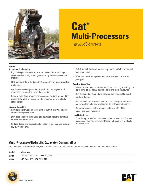
Americas NorthCat®Multi-ProcessorsH ydraulic E xcavatorsF eatures :Maximum ProductivityBig challenges are reduced to small pieces, thanks to high cutting and crushing forces generated by the cross-mounted cylinder. High productivity is the benefit of a speed valve, producing fast cycle times. Continuous 360 degree rotation positions the grapple while minimizing the need to move the machine. Enjoy a lower total system cost - compact designs mean a high productivity Multi-processor can be mounted on a relatively small carrier.Extreme VersatilityConfigure the multi-processor to your current job with one of six interchangeable jaws. Demolish concrete structures and cut rebar with the concrete crusher and cutter jaws. Reduce debris and separate rebar with the primary and second-ary pulverizer jaws.Multi-Processor/Hydraulic Excavator CompatibilityRecommended machine matches, stick-mount. Contact your local Cat ® Dealer for more detailed matching information.Model MachinesMP30329, 336, 345, 349; Apex 70, 100MP40345, 349, 365, 374, 385, 390Cut structural steel and reduce large plates with the shear and tank shear jaws. Wherever possible, replacement parts are common across jaw types.Durable Work ToolMulti-Processors are built tough to endure cutting, crushing and pulverizing thick, heavy-duty concrete and steel structures. Jaw teeth and cutting edges withstand extreme cutting and crushing forces. Jaw teeth are specially formulated steel castings which resist abrasion — through even continuous demolition applications. Replaceable wear plates protect the base metal of the jaws — and your investment.Low Noise LevelEven though Multi-Processors offer greater force and fast jaw movement, they are non-impact tools and work at a relativelylow noise level.Cat Multi-Processors2 Multi-Processors for Hydraulic ExcavatorsMulti-Processor Concrete Cutter (CC) JawConcrete Cutter (CC) jaws demolish heavily reinforced concrete with large diameter, densely pack-aged rebar. In addition, the operator can use the inner "shear" jaw to cut smaller steel structures like pipe and cables.F eatures :Three Replaceable Crusher TeethThe front part of the jaw cracks concrete to expose the rebar.Angled Top Cutting EdgesProfile of the inner jaw compresses steel, forcing it to the rear of the jaw where cutting forces are greatest.Fully Reversible KnivesIt's easy to keep performance at maximum by rotating the knives, each one has four sharp edges.Side CutterThe jaw is kept aligned while cutting and the base metal is protected from wear.Wear PlatesWelded-on plates protect the base metal.Multi-Processor Concrete Cutter (CC) Jaw SpecificationsContact your local Cat Dealer for in-depth specifications including hydraulic requirements, cutting and crushing capacities.MP30MP40Weight (housing, jaw, bracket)kg (lb)3,850 (8,190)6,370 (14,045)Weight (jaw only)kg (lb)1,260 (2,780)2,230 (4,915)A Length mm (in) 2,800 (110.2)3,500 (137.8)B Height mm (in) 1,980 (78.0)2,340 (92.1)Widthmm (in) 1,010 (39.8)1,180 (46.5)Width, Fixed Jaw mm (in) 380 (15.0)460 (18.1)Width, Moving Jaw mm (in) 130 (5.1)160 (6.3)C1Jaw Opening mm (in) 420 (16.5)600 (23.6)C2Jaw Opening mm (in) 540 (21.2)720 (28.3)C3Jaw Openingmm (in) 975 (38.4)1,280 (50.4)D Jaw Depth mm(in)890 (35.0)1,100 (43.3)Cutter Lengthmm (in) 520 (20.5)600 (23.6)Cycle Time (open, close, open)seconds6.57.5Arm Torque*Fully Open kN•m (ft•lb)1,257 (926,978)1,855 (1,368,509)Fully Closed kN•m (ft•lb)759 (559,574)1,081 (796,930)Crushing Force 1At tooth-jaw tip kN (st)1,230 (138)1,470 (165)2At cutter tip kN (st)1,780 (200)2,120 (238)3At primary bladekN(st)4,120(463)4,330(487)* T otal cylinder force × length of lever armCat Multi-ProcessorsMulti-Processors for Hydraulic Excavators 3Multi-Processor Crusher (CR) JawCrusher (CR) jaws reduce moderately reinforced concrete structures and cut rebar.F eatures :Six Replaceable Crusher TeethSix opposed teeth create stress cracks in concrete, shattering it. The teeth are bolt-on for easy replacement.Fully Reversible KnivesIt's easy to keep performance at maximum by rotating the knives, each one has four sharp edges.Wear PlatesWelded-on plates protect the base metal.Multi-Processor Crusher (CR) Jaw SpecificationsContact your local Cat Dealer for in-depth specifications including hydraulic requirements, cutting and crushing capacities.MP30MP40Weight (housing, jaw, bracket) kg (lb) 3,860 (8,510)6,370 (14,045)Weight (jaw only) kg (lb) 1,270 (2,800)2,230 (4,915)A Length mm (in) 2,770 (102.0)3,500 (137.8)B Height mm (in) 1,980 (78.0)2,380 (93.7)Widthmm (in) 1,010 (39.8)1,180 (46.5)Width, Fixed Jaw mm (in) 380 (15.0)460 (18.1)Width, Moving Jaw mm (in) 130 (5.1)160 (6.3)C1Jaw Opening mm (in) 400 (15.7)500 (19.7)C2Jaw Opening mm (in) 770 (30.3)800 (31.5)C3Jaw Openingmm (in) 1,050 (41.3)1,320 (52.0)D Jaw Depth mm(in)920 (36.2)1,100 (43.3)Cutter Lengthmm (in) 260 (10.2)250 (9.8)Cycle Time (open, close, open)seconds6.57.5Crushing Force 1At tooth-jaw tip kN (st)1,230 (138)1,480 (166)2At 2nd tooth kN (st)1,740 (196)2,150 (242)3At primary bladekN(st)3,680(414)4,600(517)321BADC2C1C3Cat Multi-Processors4 Multi-Processors for Hydraulic ExcavatorsMulti-Processor Primary Pulverizer (PP) Jaw:The wide, broad jaw holds ranks of opposed teeth, which shatter concrete, and reduce it.It's easy to keep performance at maximum by rotating the knives, each one has four sharp edges.Welded-on plates protect the base metal.Multi-Processor Primary Pulverizer (PP) Jaw SpecificationsContact your local Cat Dealer for in-depth specifications including hydraulic requirements, cutting and crushing capacities.MP30Weight (housing, jaw, bracket)kg (lb)4,180 (9,215)Weight (jaw only)kg (lb)1,590 (3,505)A Length mm (in)2,800 (110.2)B Height mm (in)1,980 (78.0)Widthmm (in)1,010 (39.8)Width, Fixed Jaw mm (in)610 (24.0)Width, Moving Jaw mm (in)370 (14.6)C1Jaw Opening mm (in)420 (16.5)C2Jaw Opening mm (in)540 (21.3)C3Jaw Openingmm (in)960 (37.8)D Jaw Depth mm(in)940 (37.0)Cutter Lengthmm (in)205 (8.1)Cycle Time (open, close, open)seconds6.5Crushing Force 1At tooth-jaw tip kN (st)1,230 (138)2At 2nd tooth kN (st)1,580 (178)3At primary bladekN(st)3,850(433)Cat Multi-ProcessorsMulti-Processors for Hydraulic Excavators 5Multi-Processor Secondary Pulverizer (PS) JawSecondary Pulverizer (PS) jaws recycle demolished concrete to gravel-sized pieces, fully separating and cleaning rebar. An inner knife sections rebar for easier handling.F eatures :Fixed Lower Jaw with Crusher BarsThe upper jaw compresses concrete against the crusher bars integrated in the lower jaw, grinding it into small pieces.Three Replaceable Crusher TeethT eeth on the upper jaw are offset from the crusher bars in the lower, creating massive stress risers in the concrete.Fully Reversible KnivesIt's easy to keep performance at maximum by rotating the knives, each one has four sharp edges.Multi-Processor Secondary Pulverizer (PS) Jaw SpecificationsContact your local Cat Dealer for in-depth specifications including hydraulic requirements, cutting and crushing capacities.MP30MP40Weight (housing, jaw, bracket)kg (lb)4,080 (8,995)6,730 (14,835)Weight (jaw only)kg (lb)1,490 (3,285)2,590 (5,710)A Length mm (in)2,950 (116.1)3,650 (143.7)B Height mm (in)2,200 (86.6)2,550 (100.4)Widthmm (in)1,010 (39.8)1,180 (46.5)Width, Fixed Jaw mm (in)580 (22.8)700 (27.6)Width, Moving Jaw mm (in)420 (16.5)480 (18.9)C1Jaw Opening mm (in)390 (15.4)500 (19.7)C2Jaw Opening mm (in)750 (29.5)950 (37.4)C3Jaw Openingmm (in)1,100 (43.3)1,400 (55.1)D Jaw Depth mm(in)970 (38.2)1,170 (46.0)Cutter Lengthmm (in)200 (7.9)250 (9.8)Cycle Time (open, close, open)seconds6.57.5Crushing Force 1At tooth-jaw tip kN (st)1,180 (133)1,450 (163)2At 2nd tooth kN (st)1,510 (170)1,870 (210)3At primary bladekN(st)4,500(506)5,040(566)Cat Multi-Processors6 Multi-Processors for Hydraulic ExcavatorsMulti-Processor Shear (S) JawShear (S) jaws are ideal for structural demolition and cutting angle and channel iron, beams, pipe and rebar.F eatures :Angled Top Cutting EdgesProfile of the jaw compresses steel, forcing it to the rear of the jaw where cutting forces are greatest.Fully Reversible KnivesIt's easy to keep performance at maximum by rotating the knives, each one has four sharp edges.Piercing TipShear pierces, then cuts — it can handle beams wider than the depth of the jaw.Side Cutters & Front CuttersSide blades and a front cross blade keep the jaw aligned and reduce the possibility of jamming.Wear PlateThe moving jaw structure is protected by a bolt-on wear plate.Multi-Processor Shear (S) Jaw SpecificationsContact your local Cat Dealer for in-depth specifications including hydraulic requirements, cutting and crushing capacities.MP30MP40Weight (housing, jaw, bracket)kg (lb)3,890 (8,575.0)6,430 (14,175)Weight (jaw only)kg (lb)1,300 (2,865.0)2,290 (5,050)A Length mm (in)2,700 (106.3)3,400 (133.9)B Height mm (in)1,680 (66.1)1,980 (78.0)Widthmm (in)1,010 (39.8)1,180 (46.5)Width, Fixed Jaw mm (in)370 (14.6)460 (18.1)Width, Moving Jaw mm (in)120 (4.7)150 (5.9)C1Jaw Opening mm (in)450 (17.7)590 (23.2)C2Jaw Opening mm (in)470 (18.5)630 (24.8)D Jaw Depthmm(in)710 (28.0)880 (34.6)Cutter Lengthmm (in)600 (23.6)760 (29.9)Cycle Time (open, close, open)seconds6.57.5Arm Torque*Fully Open kN•m (ft•lb)1,348 (994,124)2,000 (1,477,789)Fully Closed kN•m (ft•lb)907 (668,968)1,358 (1,001,792)Cutting Force1At tooth-jaw tip kN (st)1,560 (175)1,890 (212)2At primary blade kN (st)2,790 (313)3,060 (344)3At throatkN(st)7,070(794)8,840(993)* T otal cylinder force × length of lever armCat Multi-ProcessorsMulti-Processors for Hydraulic Excavators 7Multi-Processor Tank Shear (TS) JawT ank Shear (TS) jaws quickly and cleanly cut thick steel plate, leaving flat, easily handled sections. Rail cars, grain bins, oil and fuel tanks can all be rapidly reduced.F eatures :Double Row Cutting EdgesA total of nine knives around the periphery of the upper and lower jaws cut a rectangular slot in the steel, leaving the remaining sections flat and easy to handle.Fully Reversible KnivesIt's easy to keep performance at maximum by rotating the knives, each one has four sharp edges.Piercing TipPunches a hole in the tank to allow access to the cutting jaw.Multi-Processor Tank Shear (TS) Jaw SpecificationsContact your local Cat Dealer for in-depth specifications including hydraulic requirements, cutting and crushing capacities.MP30Weight (housing, jaw, bracket)kg (lb)4,380 (9,655)Weight (jaw only)kg (lb)1,790 (3,945)A Length mm (in)2,800 (110)B Height mm (in)2,100 (82.7)Widthmm (in)1,180 (46.5)Width, Fixed Jaw mm (in)340 (13.4)Width, Moving Jaw mm (in)150 (5.9)C Jaw Openingmm (in)510 (20.1)D Jaw Depth mm(in)580 (22.8)Cutter Lengthmm (in)580 (22.8)Cycle Time (open, close, open)seconds6.5Cutting Force1At tooth-jaw tip kN (st)1,850 (208)2At primary blade kN (st)2,740 (308)3At throatkN(st)5,190(583)Cat Multi-ProcessorsFor more complete information on Cat products, dealer services, and industry solutions, visit us on the web at ©2014 CaterpillarAll Rights ReservedMaterials and specifications are subject to change without notice. Featured machines in photos may include additional equipment. See your Cat dealer for available options.CAT, CATERPILLAR, their respective logos, “Caterpillar Yellow,” and the POWER EDGE trade dress, as well as corporate and product identity used herein, are trademarks of Caterpillar and may not be used without permission.GEHQ0166-06 (01-14) Replaces GEHQ0166-05。
Volvo Trucks.Driving ProgressInformación de servicioInformación de producto sobre camiones Volvo,para personal de servicios de emergenciaFL FEPrólogoLas descripciones y los procedimientos de servicio se basan en diseños y en estudios demétodos realizados hasta septiembre2012.Los productos son desarrollados continuamente.Para los vehículos y componentes fabricados luego de la fecha mencionada,pueden por lo tanto corresponder especificaciones y métodos de reparación distintos.Cuando se considere que ello pesa significativamente para el manual presente,se publicaráuna versión actualizada del mismo que incluya los cambios.En la próxima edición del manual estas modificaciones quedan actualizadas.En las instrucciones en donde hay incluido el número de operación en el rubro,tan solo se trata de una referencia al tarifario VST(Volvo Standard Times).Las instrucciones sin número de operación en el rubro son solamente una información general y no hacen referencia a VST.En esta información de servicio se utilizan los siguientes niveles en observación y advertencia. Nota:Indica un método,práctica o condición que debe ser seguido para que la función del vehículo o componente sea realizada en la forma apropiada.Precaución:Indica un procedimiento que no es seguro y que puede acarrear daños al producto.Advertencia:Indica un procedimiento que no es seguro y que puede acarrear heridas al personal o graves daños al producto.Peligro:Indica un procedimiento que no es seguro y que puede causar heridas graves al personal e incluso la muerte.Volvo Truck CorporationGöteborg,SwedenNúmero de pedido:89073870©2012Volvo Truck Corporation,Göteborg,SwedenInformación de productos-FE,FL Información de producto sobre servicios de emergencia de Volvo TrucksContenido•“Introducción”,página2•“Cabina”,página3•“Sistema eléctrico”,página4•“Habitáculo del conductor”,página7•“Ajuste del volante”,página7•“Sistema SCR”,página9IntroducciónT1008650 La finalidad de este documento es proporcionar informaciónsobre productos de tipo técnico,que pueda usarse para es-tablecer rutinas y métodos para actuaciones de salvamentoen accidentes de tráfico donde se haya visto involucrado uncamión Volvo.El presente documento se destina a los Equipos de salva-mento locales,responsables de actuaciones de salvamentoen el lugar del accidente.El documento contiene la siguienteinformación:•Cabina del conductor•Sistema eléctrico•Puesto de conducción y ajustes del volante•SRS/sistema de airbag•Sistema SCRCabinaLas cabinas antiguas están fabricadas en chapa de acero de materiales blandos unidos por soldadura.Por su lado,los modelos de cabina más modernos están fabricados en acero de alta resistencia.A continuación presentamos un dibujo esquemático de la es-tructura de cabina,donde las zonas de chapa de alta resis-tencia se han marcado de color gris claro y gris oscuro.Refuerzo decabinaC8063199Sistema eléctrico Recomendaciones generales:Hay dos tipos de interruptores para cortar la corriente eléc-trica del vehículo.Son el interruptor principal y el disyun-tor de ADR.Interruptor principal•El interruptor de suministro principal sólo funciona cuan-do el motor estádesconectado.NO corta la alimentación del tacógrafo,el sistema de cierre centralizado,la alarma Despuésde usarDisyuntor de ADR•En vehículos que transportan mercancías peligrosas de-be haber siempre un disyuntor de ADR.Cuando se usa este disyuntor se corta todo el sumi-nistro eléctrico independientemente de si el motor¡Advertencia!para desconectar Nota!Solamente la desconexión desde la batería o con el disyuntor de ADR corta TODO el suministro eléctrico.•Cuando se ha desconectado la alimentación de batería, se guarda energía en la unidad de mando de SRS duran-te unos segundos,tiempo suficiente para activar el air-bag o el tensor de cinturón de seguridad.Para asegurar que el sistema estádesenergizado,esperar unos3se-gundos después de desconectar la alimentación de labatería.•Antes de desconectar la corriente:¡Considerar la po-sible necesidad de abrir puertas o mover el asiento del conductor!(Ver:“Habitáculo del conductor”,página 7Si el asiento del conductor es ajustable eléctricamente,no seráposible ajustarlo después de cortar la electricidad porque el asiento no tiene mandos mecánicos.•La apariencia y la función varían entre diferentes inte-rruptores principales.Algunos modelos de camión care-cen de interruptor principal.¿Cómo se desconecta la corriente?•Desconectar el interruptor principal.No se desconec-tan todos los circuitos del camión;algunas partes especí-ficas del vehículo permanecen energizadas.No todas lascabinas tienen interruptor principal.•Interrumpir el circuito de batería soltando/cortando elcable de los bornes de batería.Ésta es la forma más se-gura de interrumpir la tensión.Se interrumpe toda la ten-sión,incluso del tacógrafo.Tener en cuenta que el vehículo sigue estando energiza-do si sólo se quita la llave de contacto.Con respecto aSRS,permanece energía almacenada en la unidad de man-do de SRS durante unos segundos después de cortarse elsuministro.Esta energía es suficiente para activar el airbag yel tensor de cinturón de seguridad durante hasta tres segun-dos después de cortar el suministro.La cifra indica la posición normal de la batería.1Caja de baterías de montaje lateral.Se puede montar en el lado izquierdo o derecho.2Caja de baterías de montaje posterior.T3072656Diferentes formas de cortar el suministro eléctrico:D.Interruptor principal telemandado.No existe en todos los vehículos.Pulsando el botón izquierdo dos veces dentro de cinco segundos,se desconecta el interruptor principal.Algunos circuitos permanecenenergizados.T301-7347C.Disyuntor de ADR.Sólo existe en vehículos que trans-portan mercancías peligrosas.Desconecta TODA lacorriente.C8063014B.Interruptor principal/interruptor de batería.Se encuentra en todos los vehículos.Algunos circuitos siguen excitados.A.Batería.Cuando se interrumpe el circuito de batería,empezar con el borne nega-tivo.Si es necesario cortar,hacerlo lo más cerca posible de la batería para reducir el riesgo de conexiones junto a los cables principales.Nota!¡Atención!No todos los componentes de la figura arri-ba están en todos los vehículos.Sistema de cierre centralizadoEl sistema de cierre centralizado se inmoviliza interrumpien-do el circuito de batería.En vehículos para transporte de mercancías peligrosas,el cierre centralizado también se in-moviliza desde el interruptor principal.Las puertas bloqueadas se pueden abrir desde el interior usando la empuñadura de apertura.Habitáculo del conductorDiseño del asientoExisten varios modelos de asiento para los diferentes mode-los de camión.El ajuste de posición de asiento vuelto atrás y adelante es en algunos casos mecánicos,pero los modelos más avanza-dos tienen ajuste eléctrico.Los modelos con ajuste mecánico se ajustan con una empu-ñadura situada debajo de la parte frontal del cojín de asiento,y los que tienen ajuste eléctrico se ajustan con un botón si-tuado en el lado izquierdo del asiento.Nota:los asientos con ajuste eléctrico no tienen sistema de ajuste mecánico.Para más información,ver:“Sistema eléctrico”,página 4Ajuste de asiento en sentidolongitudinalT8010409T8010449Ajuste con horquilla.Ajuste eléctrico.Ajuste del volanteHay un botón de operación neumática o una palanca mecá-nica en la columna de dirección.Cuando es necesario cortar o aserrar en el volante,la mane-ra más fácil es hacerlo en las zonas marcadas en blanco de acuerdo a la figura de abajo.El resto de las secciones están reforzadas.Perfil de refuerzo del volante y ajuste delvolanteT0013497T6009538Ajuste del volante.Cortar el volante.Sistema SCRRecomendaciones generales:•Cuando se para el motor,la solución de urea es bombea-da de vuelta al depósito de urea y se vacía la solución de urea del sistema SCR.Este proceso tarda unos dos minu-tos.Si se usa el interruptor de ADR para cortar la corrien-te antes de terminarse este proceso,el sistema puedeseguir estando presurizado y contener de solución deSi se usacuando•La urea es muy corrosiva y puede dañar conectores.Si la urea entra en contacto con conectores desenchufados, hay que cambiarlos de inmediato.No sirve de nada lim-piar porque la solución de urea se dispersa rápidamente en el cable,causando oxidación del metal.El derrameevaporaciónLas zonasen vehículosSistema SCREl sistema de urea es la parte del sistema de postratamientode los gases de escape que tienen algunos motores nuevospara cumplir con los requisitos de emisiones de Euro 4.Se inyecta una solución de urea en los gases de escape an-tes de que atraviesen el catalizador,para reducir las emisio-nes de óxidos de nitrógeno en los gases de escape.Los componentes principales del sistema SCR son:de-pósito de urea,unidad de bomba,unidad dosificadora y silenciador con catalizador incorporado.Sinopsis del sistema SCR y sus componentesprincipales:T20229851.Depósito de urea2.Unidad de bomba3.Unidad dosificadora4.SilenciadorSolución de ureaLa solución de urea,formada por agua destilada y un 32,5%de urea,es un líquido incoloro que puede tener un suaveolor a amoniaco.La solución de urea puede ser agresiva contra determinadosmateriales y se debe manipular con cuidado.La solución no es inflamable.A temperaturas altas la solución de urea se descompone enamoniaco y dióxido de carbono,y a temperaturas inferioresa –11°C la solución se puede congelar.La solución de urea es corrosiva a los metales,especialmen-te el cobre y el aluminio.Manipulación de la solución de urea:En caso de contacto con la piel:enjuague bien con agua tibia y quítese las prendas contaminadas.En caso de contacto con los ojos:enjuague bien con agua durante varios minutos y acuda a unmédico en caso necesario.En caso de inhalación:respire aire fresco y acuda a un médico en caso necesario. En caso de ingestión:beba agua89073870Spanish1.05Edición01 Volvo Truck Corporation。

产品手册Product manual三一掘进机SANY ROAD HEADER企业简介半煤岩全岩智能化快速掘进钻装机辅助设备售后服务0305091519252731 QUALITY CHANGES THE WORLD企业简介BRIEFINTRODUCTION 三一重型装备有限公司创立于2004年,是一家专业从事矿山机械、煤炭掘、采、运成套设备研发、制造及销售的大型装备制造企业,是全球装备制造头部企业三一集团旗下的核心事业部。
2009年11月25日三一重装的母公司三一国际在香港联交所主板成功上市,成为国内首家在香港上市的煤机制造企业。
主导产品覆盖综掘、采煤机、液压支架、刮板机、宽体车、矿车和破碎设备等产品门类50余种型号。
产业布局经过17年的创新发展,三一重装作为一家全球化公司,目前产品远销俄罗斯、印度、印度尼西亚、巴西、阿根廷、乌克兰、波兰、南非等20余个国家和地区。
在国内设立13个分公司,销售服务覆盖全国1000余家矿山企业。
创新研发三一重装研究院下设采掘研究院、智能化研究院、宽体车项目部、纯水支架项目部和破碎装备项目部,现已被认定为国家级企业技术中心、国家级高新技术企业,拥有国家级博士后科研工作站、行业第一家院士工作站、省级工程中心及省级工程实验室,连续四年被评为煤机行业“双十佳”企业,通过了CNAS(国内)与ANAB(国际)双重信息安全认证。
企业愿景秉持“创建一流企业,造就一流人才,做出一流贡献”的企业愿景,肩负“品质改变世界”的企业使命,秉承“自强不息,产业报国”的企业精神,三一重装致力于为全球矿产资源生产企业的绿色、安全、高效开采提供成套设备,成为其最值得信赖的长期合作伙伴,为中华民族贡献一个世界级品牌。
半煤岩关重件安全系数3倍以上,并厂内反复耐久性试验验证,使用寿命长,运输系统采用高强耐磨板,耐磨寿命提高3-5倍优质钨钴类合金,具备高强度及耐磨性,截齿损耗低内喷雾独家专利技术,内喷雾性能可靠,具备使用性和维修性。
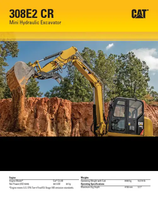
EngineEngine Model*Cat ®C3.3B Net Power (ISO 9249)48.5 kW65 hp*Engine meets U.S. EPA Tier 4 Final/EU Stage IIIB emission standards.WeightsOperating Weight with Cab 8400 kg 18,519 lb Operating Specifications Maximum Dig Depth4150 mm13'7"308E2 CRMini Hydraulic Excavator2Highperformance in a compact radius and swing boom design for greaterversatility and controllability.ContentsCompact Radius ..................................................4Operator Station ..................................................5COMPASS Control Panel ...................................6Performance and Controllability ......................8Variable Angle Boom ..........................................9Undercarriage ...................................................10Work Tools ..........................................................11Engine and Serviceability ................................12Specifi cations ....................................................14Standard Equipment .........................................17Optional Equipment...........................................18Notes . (19)The Cat 308E2 CR Mini Hydraulic Excavator delivers high performance with the versatility of a swing boomfront linkage in a durable Compact Radius design to help you work in the tightest applications. With the COMPASS display panel, Tier 4 Final/Stage IIIB engine and High Defi nition Hydraulic (HDH) system, the308E2 CR is more productive, versatile and cost effective.3Compact RadiusWork in the tightest spaces.Compact RadiusThe compact radius design gives greater machine versatility and the capability to work within confi ned areas. The radius of the upper body stays within 280 mm (11 in) of the undercarriage providing fl exibility for different work site applications with a reduced risk of damage and less stress for the operator.This allows the operator to concentrate on the work being done without having to worry about damaging the back of the machineor other job site obstacles.45Comfortable Working EnvironmentSpacious and comfortable operator station with excellent visibility and legroom keeps the operator comfortable and helps reduce fatigue. All hydraulic functions are fully pilot operated, lowering owning and operating costs and resulting in less downtime. The operator station also features:• Heated, air suspension seat • COMPASS display panel • Ergonomic joysticks• Dynamic operator sound pressure 70 dB(A) ISO 6396• Average exterior sound pressure 99 dB(A) ISO 6395 – dynamic testOperator StationSuperior comfort to keep you productive throughout the work day.The COMPASS control panel on the Cat E2 Series mini hydraulicexcavators was specifi cally designed by Caterpillar for compactexcavators. It adds several new features to the machines increasingthe amount of customer value. All of the following features arestandard on all E2 Series models.C omplete – All of the control panel features are standard on allE2 Series modelsO peration – Simple operation of the pattern changer, hydraulic quickcoupler and fuel gauge visibility all at the push of a buttonM aintenance – Maintenance intervals, diagnostics and work hoursP erformance – Maintain optimum performance levels with adjustablework tool fl ow featuresA ndS ecurity – Anti theft device with individual user and masterpasswordsS ystem – Ergonomically designed control panelPasscode Protected Security SystemA standard anti-theft device comes on every E2 Series compactexcavator. A fi ve digit alphanumeric password is required to start themachine when the anti-theft feature is enabled. There is a masterpassword and up to fi ve user passwords can be created by theowner if desired.Keep your machine safe on a busy job site by locking it when youare not around.Adjustable Auxiliary Work Tool Flow ControlThe E2 Series machines feature simple adjustability of the fl ow goingdown the boom and stick to the work tool. Both the standard mainline and optional secondary auxiliary hydraulics can be adjustedon a scale of 1–15 through a few buttons on the control panel.Adjust the fl ow to your different tools with a simple push of a button. COMPASS Control PanelComplete, Operational, Maintenance, Performance and Security System.6Rearview CameraIncrease operator productivity and effi ciency with enhanced visibility with the rear view camera.Work more confi dently with greater visibility.Continuous FlowOnce this feature is enabled through a button on the monitor, the E2 Series machines can run in continuous fl ow mode. With the auxiliary hydraulics on the right hand joystick, just hold the roller switch at the desired fl ow rate and direction for 2.5 seconds and the machine will maintain that fl ow rate until it is turned off.Maintain hydraulic fl ow to your tools at any fl ow and in any direction with the simple push of a button.Pattern ChangerChange the operating pattern between excavator and backhoe with a simple press of a button from the comfort of the cab. (Optional in Europe)Exclusive push button pattern changer is safe and easy.Maintenance and Performance InformationEasily keep track of various maintenance and performance parameters of your machine.Reset the maintenance intervals and ensure the machine is receiving proper care maximizing the life of the machine.Site Reference SystemOutput from pitch and roll sensors aid in grading and level trenching for improved effi ciency and job site fi nishing.Finish the job faster with site information.UNLOCK the new features and experience the value of the exclusive COMPASS control panel on the Cat E2 Series compact excavators7High digging forces that provide power through even the most compacted ground, coupled with direct, smooth control through responsive hydraulics, ensure that the Cat 308E2 CR delivers the high productivity that customers demand.ControllabilityThe Cat 308E2 CR front linkage has been perfectly balanced with the hydraulics to deliver the high level of control required for fi ne grading and landscaping applications.• Automatic two speed function improves job site maneuverability by balancing high speed travel requirements and control.• Joystick mounted auxiliary control enhances machine controllability. The intuitive controls give fi ne modulation.• Auxiliary lines including quick connectors are fi tted as standard, meaning the Cat 308E2 CR comes ready to work.• Optional boom and stick lowering check valve includes integral overload warning device.High Definition Hydraulic System• Delivers fuel savings, effi ciency, controllability and precision.• Industry leading variable displacement, load sensing, fl ow sharing system.Lift CapacityTo meet the diverse needs of today’s customer, the 308E2 CR has high level lift capacity and outstanding stability – all in a compact radius design to provide on site versatility to get the job done.CounterweightAn optional rear counterweight can be added to provideadditional lift capacity and stability.Performance and ControllabilityPowerful digging combined with smooth responsive control.8Variable Angle BoomIncreased fl exibility and versatility.Durable Front LinkageUptime and service intervals are increased with durable and reliable booms, sticks and linkage pins. Each boom and stick is builtto provide superior strength to withstand any tough application. The variable angle boom option offers fl exibility and versatilityin the working envelope.With full extension, the working range offers a maximum dig depth extending to 3980 mm (157 in). The maximum reach extends760 mm (30 in) beyond the standard boom and stick confi guration to 7780 mm (306 in). The working height reaches 1360 mm (54 in) beyond the standard boom and stick confi guration to 8000 mm (315 in). When retracted, the Cat 308E2 Variable Angle BoomMini Excavator can work closer to the blade and tracks, providing increased lifting capacity while working productively inconfi ned areas.910Depending on the customers application, the Cat 308E2 CR has three different track options to choose from, allowing the correct machine confi guration to suit the job.Rubber BeltProvides the lowest ground disturbance of all track options with excellent traction in conditions that are soft underfoot. The standard track offering is 450 mm (17.7 in) width.Steel TrackGood for demolition and heavy duty applications. A triple grouser track is available in two width options: 450 mm (17.7 in) and 600 mm (23.6 in).Steel Track with Rubber PadsThe 450 mm (17.7 in) wide shoe has four holes to attach the rubber pads to the steel track shoes. This option prevents damage to paved road surfaces and minimizes noise and vibration during travel while providing maximum stability.UndercarriageExcellent stability.Blade WidthsThe dozer blade is an important and useful tool for the Hydraulic Mini Excavator used for backfi lling trenches,levelling, landscaping and site clean up. There are two blade width options available to accommodate the differences in track widths.The blade comes standard with a replaceable weld-on dozer cutting edge constructed of hardened steel for longer life.Tie Down PointsLarge oval tie down points are located in two positions on the undercarriage for easy and safe machine tie down fortransportation.11Wide Range of Work ToolsA wide range of Cat Work Tools have been designed specifi cally to get the best out of your machine and deliver excellent value through high productivity and long life.Available work tools include:• Buckets (heavy duty and heavy duty capacity)• Tilting and Swing Ditch Cleaning Buckets • Hydraulic Hammers • Augers• Vibratory Compactors • Shears • Rippers• Dual Lock Mechanical Coupler • Dual Lock Hydraulic Coupler • Tilting CouplerTo maximize performance and productivity, Cat mechanical and hydraulic quick couplers are compatible with all standard work tools, enabling the operator to simply release one work tool and pick up another.One-way fl ow (hammer) and two-way fl ow (auger) auxiliary lines with quick connectors are fi tted as standard. This allows the machine to adapt to a wide variety of applications without re-confi guring the auxiliary lines. Versatility is further enhanced with the option of a second auxiliary supply(for a rotating grapple).Work ToolsMatched to meet your application needs.Customer SupportYour Cat dealer is ready to assist you with your purchase decision and everything after.• Financing packages are fl exible to meet your needs • Unmatched parts availability keeps you working• Make comparisons of machines, with estimates of component life, preventative maintenance and cost of production• For more information on Cat products, dealer services and industry solutions, visit 12Engine and ServiceabilitySuperior power with easy access and minimal maintenance requirements keep you working.EngineThe Cat C3.3B electronic engine delivers quiet operation with superior power and fuel effi ciency while meeting Tier 4 Final/Stage IIIB emission standards.Easy ServiceConvenient service features make maintenance easy, reducing your downtime:• Lifting side hood allows access to air fi lter, main implement valve,1-way/2-way auxiliary fl ow selector, accumulator, fuel fi lter and hydraulic tank. This eliminates the need to lift the cab when maintaining and servicing the machine.• Swing open door provides access to major components and service points including engine oil check and fi ll, vertically mounted engine oil fi lter, starter motor and alternator.• S·O·S SM oil sampling valve allows easy sampling of the hydraulic fl uid for preventative maintenance.• The 308E2 CR is Product Link™ ready and the Cat Product Link system simplifi es equipment fl eet tracking. Using satellite or cellular technology, the system automatically reports information such as location, machine hours, active and logged service codes and security alarms.Power on DemandAutomatic system ensures optimal fuel effi ciency through appropriate engine rating to meet all operational requirements as needed.Auto Engine ShutdownEngaging this feature allows the operator to save fuel by powering down the machine after a designated inactive period. The operator can adjust the range from 1-15 minutes to meet their needs. The system will only shut down after the set time, provided the hydraulic lever is up. Electronics will remain powered after shutdown.13308E2 CR Mini Hydraulic Excavator Specifications1415308E2 CR Mini Hydraulic Excavator SpecificationsDimensionsLift Capacities at Ground Level*Lift Point Radius 4000 mm (13'1")6050 mm (19'10")Front Side Front Side Blade Down kg 365017101880920lb 8,0463,7704,1442,028Blade Upkg 18401530970820lb4,0563,3732,1381,808* The above loads are consistent with hydraulic excavator lift capacity rating standard ISO 10567:2007 and they do not exceed 87% of hydraulic lifting capacity or 75% of tipping capacity. The excavator bucket weight is not included on this chart. Lifting capacities are for standard stick.Standard StickLong Stick mm ft/in mm ft/in 1Dig Depth 415013'7"469015'5" 2Vertical Wall29809'9"355011'8" 3Maximum Reach at Ground Level 682022'9"735024'1" 4Maximum Reach702023'0"754024'9" 5Maximum Dig Height664021'9"699022'11" 6Maximum Dump Clearance 467015'4"501016'5" 7Linkage In Minimum Radius 28009'2"328010'9" 8Tail SwingStandard Counterweight 14504'9"14504'9" 9Maximum Blade Height4201'5" 4201'5"10Maximum Blade Depth3201'1" 3201'1"11Boom Height in Shipping Position22807'6"22307'4"12O/A Shipping Height 25508'4"25508'4"13Swing Bearing Height 7352'5" 7352'5"14O/A Undercarriage Length 29039'6"29039'6"15O/A Shipping Length 638020'11"634020'10"16Boom Swing Right 10103'4"10103'4"17Boom Swing Left 6352'1" 6352'1"18Track Belt/Shoe Width 4501'6" 4501'6"19O/A Track Width23207'7"23207'7"1119308E2 CR Mini Hydraulic Excavator Specifications Dimensions with Variable Angle BoomStandard Stick with Angle Boom ExtendedStandard Stick with Angle Boom Retractedmm in mm in1Dig Depth398015737101462Vertical Wall382015036001423Maximum Reach at Ground Level763230063652514Maximum Reach778030665502585Maximum Dig Height800031552002056Maximum Dump Clearance608023933601327Linkage In Minimum Radius292511532351278Tail SwingStandard Counterweight1450 571450 57With Extra Counterweight1565621565629Maximum Blade Height 420 17 420 1710Maximum Blade Depth 320 13 320 1311Boom Height in Shipping Position22809022008712O/A Shipping Height2550100255010013Swing Bearing Height 735 29 735 2914O/A Undercarriage Length2903114290311415O/A Shipping Length7010276579522816Boom Swing Right10104010104017Boom Swing Left 635 25 635 2518Track Belt/Shoe Width 450 18 450 1819O/A Track Width232091232091Lift Capacities at Ground Level with Variable Angle BoomVariable Angle Boom Minimum*Variable Angle Boom Maximum*Lift Point Radius5000 mm (16'5")5500 mm (18'1")5000 mm (16'5")6800 mm (22'4")Front Side Front Side Front Side Front Side Blade Down kg2354107090290224799451451575lb5,1912,3591,9891,9895,4662,0843,1991,268 Blade Up kg129410709029021164945714575lb2,8532,3591,9891,9892,5672,0841,5741,268 * The above loads are in compliance with hydraulic excavator lift capacity rating standard ISO 10567:2007 and they do not exceed 87% of hydraulic lifting capacity or 75% of tipping capacity. The excavator bucket weight is not included on this chart. Lifting capacities are for standard stick.16308E2 CR Standard EquipmentENGINE• Cat C3.3B diesel engine (meets Tier 4 Final/ Stage IIIB emission standards)• Automatic engine idle• Automatic engine shut-off• Automatic two speed travel• Diesel Particulate Filter(North America only)• Diesel Oxidation Catalyst(North America only)• Fuel and water separator• Power on demandHYDRAULIC SYSTEM• 1-way and 2-way (combined function)• Accumulator• Automatic swing parking brake• Auxiliary hydraulic lines• Adjustable auxiliary relief• Auxiliary line quick disconnects• Cat interlock system: hydraulic lockout • Continuous auxiliary fl ow• Ecology drain• Hydraulic oil cooler• High defi nition hydraulics• Load sensing/fl ow sharing OPERATOR ENVIRONMENT• 100% pilot control ergonomic joysticks• Adjustable armrests• Air conditioning/heat• COMPASS: complete, operation,maintenance, performance andsecurity system–Multiple languages• Cup holder• High back suspension seat, heated• Hydraulic neutral lockout bar• Interior light• Literature holder• Pattern changer (optional in Europe)• Radio (optional in Europe)• Site reference system: leveling• Tool storage area• Travel control pedals with hand levers• Washable fl oor mat• Windshield wiperUNDERCARRIAGE• Dozer blade with fl oat function• Track, rubber belt, 450 mm (18 in) width• Tie down eyes on track frame• Towing eye on base frameFRONT LINKAGE• 180 degree bucket rotation• Certifi ed lifting eye on bucket linkage(optional in Europe)• Front shovel capable• Thumb ready stickELECTRICAL• 12 volt electrical system• 60 ampere alternator• 650 CCA maintenance free battery• Fuse box• Ignition key start/stop switch• Slow blow fuse• Warning hornLIGHTS AND MIRRORS• Cab and boom light with time delaycapability• Mirror, rear view, cab leftSAFETY AND SECURITY• Anti-theft system (COMPASS)• Caterpillar Corporate “One Key” System• Door locks• Lockable fuel cap• Rearview camera• Retractable seat belt• Roll Over Protective Structure (ROPS)(ISO 12117-2)• Tip Over Protective Structure (TOPS)(ISO 12117)• Top guard – ISO 10262 (Level II)• Travel alarm (optional in Europe)Standard EquipmentStandard equipment may vary. Consult your Cat dealer for details.17308E2 CR Optional EquipmentENGINE• Engine block heater HYDRAULIC SYSTEM• Quick coupler lines• Boom lowering check valve*• Stick lowering check valve*• Secondary auxiliary hydraulic lines* *Standard on V AB confi guration.UNDERCARRIAGE• Blade, weld on• Track, triple grouser (steel), 450 mm (18 in)• Track, triple grouser (steel) with rubber pad,450 mm (18 in)• Track, triple grouser (steel), 600 mm (24 in)FRONT LINKAGE• Quick coupler: manual or hydraulic• Thumb• Buckets• Full range of performance matchedwork tools–Auger, hammer, shear, ripperLIGHTS AND MIRRORS• Mirror, cab rearSAFETY AND SECURITY• Battery disconnect• Front wire mesh guard• Front steel plate guard• Rain guardTECHNOLOGY• Product LinkOTHER ATTACHMENTS• Counterweight, extra, 1121 kg (2,493 lb)*Optional EquipmentOptional equipment may vary. Consult your Cat dealer for details.18Notes19AEHQ7916 (08-2016) For more complete information on Cat products, dealer services, and industry solutions, visit us on the webat © 2016 CaterpillarAll rights reservedMaterials and specifi cations are subject to change without notice. Featured machines in photos may includeadditional equipment. See your Cat dealer for available options.CAT, CATERPILLAR, , their respective logos, “Caterpillar Yellow” and the “Power Edge”trade dress, as well as corporate and product identity used herein, are trademarks of Caterpillar and maynot be used without permission.。
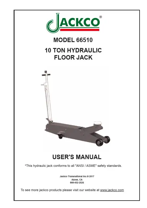
Jackco Transnational Inc.©2017Azusa , CA 888-452-252610 TON HYDRAULICFLOOR JACKUSER'S MANUALMODEL 66510*This hydraulic jack conforms to all "ANSI / ASME" safety standards.To see more jackco products please visit our website at FOR YOUR SAFETY•Read these safety instructions carefully and keep this manual in an easy to find place as you may need to use it again.•Non-compliance with these rules may result in injury or damage to the jack or the vehicle.•Do not modify the jack in any way.•Never exceed the rated capacity of the jack.•This jack is a lifting device only and should never be used to move the vehicle.•The jack should be supported on a solid and level ground. Never use the jack in a surface where it may sink into the ground.•Ensure that there are no persons inside the vehicle to be lifted. Switch off the engine and apply the brake.•Position the jack under the manufacturer’s recommended lifting point for the vehicle. Off-centered loads can slip and accidents may result.•During raising and lowering of the load, precautions should be taken to avoid movement of the vehicle. Traffic may cause the raised vehicle to rock during roadside use of the jack.•Never work under a raised vehicle without supporting it with mechanical/jack stands.•Never position any part of your body near the movable parts of the jack.•Ensure that there are no persons or obstructions underneath the vehicle prior to lowering.•Do not adjust the overload bypass valve under any circumstance.Use wheel chocks appropriately.2SPECIFICATIONOPERATING INSTRUCTIONImportant: Sometimes during shipment and handling, air gets into the hydraulic system, causing poor lifting performance. Before initial operation, purge any air from the system by fully opening release (Turn handle knob (#3-8) counter-clockwise). Then, while holding the saddle down, pump pedal (#3-2) rapidly several times.To Lift a Vehicle:1. T urn handle knob (#3-8) clockwise until resistance is felt to close release valve.Do not over-tighten.2. P lace jack directly under object to be lifted. Make sure saddle takes up weightfirmly and centrally. Check positioning under slight load to confirm jack or load will not slip.3. R aise jack by pumping handle until desired height is reached. After lifting, secureload by appropriate means. Do not use jack as the only means of support.To Lower a vehicle:1. S lowly turn handle knob (#3-8) counter-clockwise. Speed of descent is controlledby amount release valve is turned.3• Checking hydraulic oil level1. O pen release valve (Turn handle knob (#3-8) counter -clockwise and push ram to its lowest position.2. R emove filler plug.3. F ill the clean hydraulic jack oil .Do not use hydraulic brake fluid .4. R einstall filler plug .• Only original replacement parts should be used. Extremely Important: never use brake fluid.• When the jack is not in use, make sure the lifting arm is fully retracted to avoid corrosion.• Keep the jack in a clean, dry place and out of children’s reach.• Replace the hydraulic fluid in the reservoir at least once a year. To check the hydraulic fluid level, lower the lifting arm completely.• The hydraulic fluid level should be just below the filler plug. Replenish if necessary, and reinstall the rubber filler plug. Excessive hydraulic oil may render the jack inoperative.• Inspect the jack before each use. Take corrective action or remove the jack from service if any of the following problems are found:a. Cracked or damaged frameb. Leaking hydraulic fluidc. Scored, damaged piston rodd. Loose hardwaree. Modified equipment• Keep warning labels and instructional decals clean and readable. You may use a mild soap solution to wash external surfaces of the jack.MAINTENANCEImportant: Both the maintenance and repair of the jack may only be performed by qualified persons, who have sufficient knowledge of the hydraulic system used in thesejacksRegularly lubricate the moving parts in the wheels, arms, handle and pump roller pin.4TROUBLESHOOTINGCaution: To prevent personal injury, all inspection, maintenance, and repairprocedures must be performed when the jack is free of load.PARTS LISTLIMITED ONE YEAR WARRANTYJackco Transnational Inc. warrants all Jackco equipment and tools to the original purchaser against any manufacturing defect in material or workmanship for a period of one (1) year from the original date of purchase. If the defective equipment or tool is determined to be covered under this warranty, it shall be repaired or replaced at manufacturer's discretion without charge, provided that the equipment or tool must be returned with proof of purchase to the dealer and freight prepaid, if returned to the manufacturer. This warranty shall not apply to damage due to accident, negligent use, and lack of maintenance, abuse or applications other than the specific function the equipment or tool is designed for.No other warranties, expressed or implied, including those of merchantability or fitness for particular purpose shall be applicable to Jackco except as specifically stated herein. In no event shall Jackco be liable to any party for any special, direct, indirect, consequential, punitive damage of any nature caused by the sale or use of the equipment or tool.Note: This warranty gives the original purchaser specific legal rights which may very from state to state.Jackco Transnational Inc. © 2017Azusa, CA888-452-2526 。
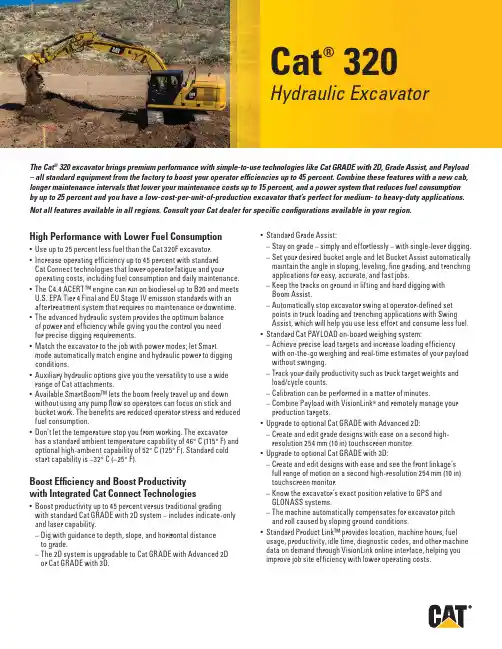
Cat® 320Hydraulic ExcavatorThe Cat® 320 excavator brings premium performance with simple-to-use technologies like Cat GRADE with 2D, Grade Assist, and Payload – all standard equipment from the factory to boost your operator efficiencies up to 45 percent. Combine these features with a new cab, longer maintenance intervals that lower your maintenance costs up to 15 percent, and a power system that reduces fuel consumption by up to 25 percent and you have a low-cost-per-unit-of-production excavator that’s perfect for medium- to heavy-duty applications. Not all features available in all regions. Consult your Cat dealer for specific configurations available in your region.High Performance with Lower Fuel Consumption• Use up to 2 5 percent less fuel than the Cat 3 20F excavator.• Increase operating ef fi ciency up to 4 5 percent with standardCat Connect technologies that lower operator fatigue and youroperating costs, including fuel consumption and daily maintenance.• The C 4.4 ACER T™ engine can run on biodiesel up to B2 0 and meetsU.S. EPA Tier 4 Final and EU Stage IV emission standards with anaf t er t reatment system that requires no maintenance or downtime.• The advanced hydraulic system provides the optimum balanceof power and ef fi ciency while giving you the control you needfor precise digging requirements.• Match the excavator to the job with power modes; let Smar tmode automatically match engine and hydraulic power to diggingconditions.• Auxiliar y hydraulic options give you the versatilit y to use a widerange of Cat at t achments.• Available Smar t Boom™ lets the boom freely travel up and downwithout using any pump flow so operators can focus on stick andbucket work. The benefits are reduced operator stress and reducedfuel consumption.• Don’t let the temperature stop you from working. The excavatorhas a standard ambient temperature capabilit y of 4 6° C (115° F) andoptional high-ambient capabilit y of 5 2° C (12 5° F ). S t andard coldstar t capabilit y is – 32° C (–2 5° F ).Boost Efficiency and Boost Productivitywith Integrated Cat Connect Technologies• Boos t productivit y up to 4 5 percent versus traditional gradingwith s t andard Cat GR A DE with 2D system – includes indicate-onlyand laser capabilit y.– Dig with guidance to depth, slope, and horizontal distanceto grade.– The 2D system is upgradable to Cat GR A DE with Advanced 2Dor Cat GR A D E with 3D.• S t andard Grade Assist:– S t ay on grade – simply and ef f or t lessly – with single-lever digging.– Set your desired bucket angle and let Bucket Assis t automaticallymaintain the angle in sloping, leveling, fine grading, and trenchingapplications for easy, accurate, and fast jobs.– Keep the tracks on ground in lif t ing and hard digging withBoom Assist .– Automatically s t op excavator swing at operator-defined setpoints in truck loading and trenching applications with SwingAssist , which will help you use less ef f or t and consume less fuel.• S t andard Cat PAYLOAD on-board weighing system:– Achieve precise load targets and increase loading ef fi ciencywith on-the-go weighing and real-time es t imates of your payloadwithout swinging.– Track your daily productivit y such as truck target weights andload/cycle counts.– Calibration can be per f ormed in a mat t er of minutes.– Combine Payload with VisionL i nk® and remotely manage yourproduction targets.• Upgrade to optional Cat GR A DE with Advanced 2D:– Create and edit grade designs with ease on a second high-resolution 2 54 mm (10 in) touchscreen monitor.• Upgrade to optional Cat GR A DE with 3D:– Create and edit designs with ease and see the front linkage’sfull range of motion on a second high-resolution 25 4 mm (10 in)touchscreen monitor.– Know the excavator ’s exact position relative to GPS andGLONASS systems.– The machine automatically compensates for excavator pitchand roll caused by sloping ground conditions.• S t andard Product Link™ provides location, machine hours, fuelusage, productivit y, idle time, diagnostic codes, and other machinedata on demand through V i sionLink online inter f ace, helping youimprove job site ef fi ciency with lower operating cos t s.Cat® 320 Hydraulic ExcavatorWork in Comfort in the All-New Cab• Choose bet w een Comfor t and Deluxe cabs – both with automatic climate control.• Sit in wide seats that adjust for all size operators; s t ay warm with the Deluxe heated seat.• Enjoy wide spacing bet w een consoles for a more comfor t able environment .• Get in and out of the cab easier using the tip-up lef t console (Deluxe cab only).• Advanced viscous mounts reduce cab vibration up to 5 0 percent over previous excavator models.• Control the excavator comfor t ably with easy-to-reach controlsall located in front of you.• S t ow your gear with plent y of in-cab storage beneath and behind the seat , overhead, and in the consoles. A cup holder, document holder, bot t le holder, and coat hook are also provided.• Use the s t andard radio’s USB por t s and Bluetooth® technologyto connect personal devices and make hands-free calls.Simple to Operate• S t ar t the engine with a push but t on; use a Bluetooth key fob, smar t phone app, or the unique Operator ID function.• Program each joystick but t on, including response and pat t ern, using Operator ID; it will also remember climate control fanand radio set t ings.• Navigate quickly on the standard high-resolution 2 03 mm(8 in) touchscreen monitor, or with the optional 2 54 mm (10 in) touchscreen monitor, or with the aid of the jog dial control.• A second 2 54 mm (10 in) monitor is available for the advanced grade control.• Not sure how a function works or how to maintain the excavator? Always have the operator ’s manual at your finger t ips in the touchscreen monitor.Maintenance• E x pect up to 15 percent less maintenance cost than the 3 20E. (Savings calculated over 12 ,0 00 machine hours.)• Do all daily maintenance at ground level.• Check engine oil level quickly and safely with the new ground-level engine oil dipstick; fill and check engine oil on top of the machine with a conveniently located second dipstick. • Track your excavator ’s filter life and maintenance inter v als via the in-cab monitor.• Do no required maintenance on the Cat Clean Emissions Module. • Change all fuel filters at a synchronized 5 00 hours.• E x pect the new air intake filter with precleaner to last up to1, 000 hours – a 10 0 percent increase over the previous filter.• The new hydraulic oil filter provides improved filtration per f ormance, anti-drain valves to keep oil clean when the filter is replaced, and longer life with a 3, 000 hour replacement inter v al – 5 0 percent longer than previous filter designs.• The new high-ef fi ciency electric cooling fans only run when needed and reverse to keep cores free from debris.• S·O·S SM por t s simplif y maintenance and allow for quick , easyex t raction of fluid samples for analysis.Safety• Work safely under structures or near traf fi c with the s t andard 2DE-fence feature integrated right out of the factor y, which prevents any par t of the excavator from moving outside operator-defined set points to avoid hazards and job site accidents.• Access 10 0 percent of daily maintenance points from ground level – no need for you to climb on top of the excavator.• The standard ROPS cab meets ISO 12117-2:2 008 requirements. • Enjoy great visibilit y into the trench, in each swing direction, and behind you with the help of smaller cab pillars, larger windows, and a flat engine hood design.• The standard hydraulic lockout lever isolates all hydraulic and travel functions in the lowered position.• Ground-level shut-of f switch stops all fuel to the engine when activated and shuts down the machine.• A rear v iew camera is s t andard, and a right-side-view camerais optional. Upgrade to 3 60° visibilit y and you’ll easily visualize objects and personnel around the excavator in a single view.• New right-hand ser v ice plat f orm design provides easy, safe, and quick access to upper ser v ice plat f orm; the ser v ice plat f orm steps use anti-skid punch plate to prevent slipping.• Available boom and stick lowering check valves prevent reverse flow, keeping your front linkage securely in place should the hydraulic sys t em unexpectedly lose power.• The handrails comply with ISO 2 867:2011 requirements.• The lower frame meets ISO 15 818:2 017 lif t ing and tie-down requirements.Cat® 320 Hydraulic Excavator Standard and Optional EquipmentStandard and optional equipment may vary. Consult your Cat dealer for details.Standard Optional CABROPS, standard sound suppression 9 Mechanically adjus t able seat 9Air-adjustable seat with heat (Deluxe only) 9 High-resolution 2 03 mm (8 in) 9LCD touchscreen monitorHigh-resolution 2 54 mm (10 in) 9 LCD touchscreen monitorCAT CONNECT TECHNOLOGYCat Product L i nk 9Cat GR A DE with 2D 9Cat GR A DE with Advanced 2D 9 (not available on SL R)Cat GR A DE with 3D (not available on SLR) 9 Cat GR A DE with Assist 9Cat PAY L OA D9ENGINEThree selectable power modes 9Auto engine idle shutdown 94 6° C (115° F ) ambient cooling capacit y952° C (12 5° F ) high-ambient cooling capacit y9– 32° C (–2 5° F ) cold star t capabilit y9Reversing electric cooling fans 9Biodiesel capabilit y up to B2 09 HYDRAULIC SYSTEMBoom and stick regeneration circuits 9Boom and stick lowering check valves 9 Auto hydraulic warm up 9Auto t w o-speed travel 9Boom and stick drif t reduction valve 9Hammer return filter circuit 9 Combined flow/high-pressure 9 auxiliar y circuitMedium-pressure circuit 9 Quick coupler circuit for Cat Pin Grabber 9Standard Optional BOOM AND STICKS5.7 m (18'8 ") reach boom, 2.9 m (9'6") stick 98.8 5 m (29'0 ") SL R boom, 6.2 8 m (20'7 ") 9 SL R s t ickUNDERCARRIAGE AND STRUCTURES6 00 mm (24") triple grouser shoes 970 0 mm (2 8") triple grouser shoes 979 0 mm (31") triple grouser shoes 99 00 mm (3 5") triple grouser shoes 9 Tie-down points on base frame 942 00 kg (9, 300 lb) counter w eight 9for HD boom and stick470 0 kg (10, 400 lb) counter w eight 9for SL R boom and s t ickELECTRICAL SYSTEMTwo 1, 000 CCA maintenance-free bat t eries 9 Programmable time-delay L E D 9working lightsLED chassis light, lef t-hand/right-hand 9boom lights, cab lightsSERVICE AND MAINTENANCESampling por t s for Scheduled Oil Sampling 9 (S·O·S)Ground-level and plat f orm-level engine 9oil dips t icksRemote flash 9SAFETY AND SECURITYRear v iew camera 9Right-hand-side camera 9* 9* Right-hand mirror 93 60° visibilit y9 Ground-level engine shutof f switch 9Right-hand handrail and hand hold 9Signaling /warning horn 9*Europe standard; other regions optional.Cat® 320 Hydraulic Excavator Technical SpecificationsEngine Model Cat C 4.4 ACER T Gross Power – ISO 14 396/SA E J19 95 12 2 kW 16 4 hp Net Power – ISO 924 9/SA E J13 49121 kW 162 hp Engine RPMOperation 1,65 0 rpmTravel 1, 800 rpmBore 10 5 mm 4 in Stroke 127 mm 5 in Displacement 4 .4 L 269 in 3Main System – Maximum Flow (Implement) 42 9 L /min 113 gal /min Maximum Pressure – Equipment – Normal 3 5 0 00 kPa 5,0 75 psi Maximum Pressure – Equipment –Heav y L i f t Mode3 8 0 00 kPa 5, 510 psi Maximum Pressure – Travel 34 3 00 kPa 4, 974 psi Maximum Pressure – Swing 2 6 8 00 kPa 3, 886 psiOperating Weight – Nor t h America 2 2 5 00 kg 4 9,6 00 lb • Reach boom, R2.9 m (9'6 ") stick, HD 1.19 m 3 (1.5 6 yd3) bucket and 79 0 mm (31 in) triple grouser shoes, 4.2 mt (9, 300 lb) counter w eight.Operating Weight – E urope/Australia21 9 00 kg 4 8, 300 lband New Zealand• Reach boom, R2.9 m (9'6 ") stick, HD 1.19 m 3 (1.5 6 yd3) bucket and 6 00 mm (24 in) triple grouser shoes, 4.2 mt (9, 300 lb) counter w eight.Fuel Tank 3 45 L 8 6.6 gal Cooling System 2 5 L 6.6 gal Engine Oil 15 L 4 gal Swing Drive (each) 5 L 1. 3 gal Final Drive (each) 5 L 1. 3 gal Hydraulic System (including tank) 2 34 L 61.8 gal Hydraulic Tank 115 L 3 0.4 gal DEF Tank 3 9 L 10.3 gal Boom Reach 5.7 m (18'8 ") Stick Reach 2.9 m (9'6 ") Bucket 1.19 m3 (1.56 yd3) Shipping Height (top of cab) 2 960 mm 9'9 " Handrail Height 295 0 mm 9'9 " Shipping Length 95 30 mm 31'3 " Tail Swing Radius 2 830 mm 9'3 " Length to Center of Rollers 3 650 mm 12'0 " Ground Clearance 470 mm 1'7 " Track Gauge 2 380 mm 7'9 " Transpor t W i dth – 6 00 mm (24") Shoes 2 980 mm 9'9 " Transpor t W i dth – 79 0 mm (31") Shoes 3170 mm 10'5" Counter w eight Clearance 10 48 mm 3'5"Stick Reach 2.9 m (9'6 ") Bucket 1.19 m3 (1.56 yd3) Maximum Digging Depth 6 72 0 mm 2 2'1" Maximum Reach at Ground Level 9 860 mm 32'4" Maximum Cut t ing Height 9 370 mm 3 0'9 " Maximum L o ading Height 6 490 mm 21'4" Minimum Loading Height 2170 mm 7'1" Maximum Depth Cut for 24 40 mm (8'0 ")Level Bot t om655 0 mm 21'6 " Maximum Ver t ical Wall Digging Depth 519 0 mm 17'0 " Bucket Digging Force (ISO) 15 0 kN 3 8, 811 lbf S t ick Digging Force (ISO) 10 6 kN 2 3, 911 lbf Bucket Digging Force (SA E) 13 4 kN 3 0,10 4 lbf S t ick Digging Force (SAE) 10 3 kN 2 3,212 lbf Boom Reach 5.7 m (18'8 ")F o r more complete infor m ation on Cat product s, dealer ser v i ces, and indus t r y solu t ions, visit us on t h e web at ww © 2 017 CaterpillarAll righ t s reser v edMaterials and speci fi cations are subject to change wi t hout notice. Featured machines in pho t o s may include addit i onal equipment . See your Cat dealer for available options.C A T, CAT E R PIL L A R, S A F E T Y.C A , t h eir respec t i ve logos, “Caterpillar Yellow ” and the “Power Edge” trade dress, as well as corporate and product iden t i t y used herein, are t r ademarks of Caterpillar and may no t be used wi t hout permission.A E X Q 219 0-01 (12-2 017)Replaces AE X Q 2190Build Number: 0 7A (Nor t h America, Europe, A N Z)。
Cat® 313FHydraulic ExcavatorThe Cat® 313F excavator is a reliable and versatile solution for your light to medium duty applications. Featuring a fuel-effi cientCat C4.4 engine, robust frames and components, and a state-of-the-art hydraulic system, the 313F allows you to move material all day with speed and precision.Not all features are available in all regions. Consult your Cat dealer for specifi c configurations available in your region.High Performance• The Cat C 4.4 engine can run on biodiesel up to B2 0 and meetsU.S. EPA Tier 4 Final and EU Stage IV emission standards with anaf t er t reatment system that requires no maintenance or downtime.• Two power modes – eco and high power – help you manage fuelfor the work you need to do.• Reduce engine speed and minimize fuel consumption during no-loador light-load conditions with automatic engine speed control (AEC).• Engine idle shutdown allows you to set inter v als so you don’twaste fuel; it also helps reduce emissions and wear and tear onyour excavator.• Work at altitudes up to 2 300 m (7,5 45 f t) above sea level withoutde-rating.• Get the job done with a power f ul and ef fi cient hydraulic sys t em.Major components are located close together creating less friction,reducing pressure drops, and increasing power to the ground.• Save energy and improve fuel ef fi ciency with boom and stick oilregeneration. This feature improves controllabilit y, increasesproductivit y, and reduces operating costs.• Don’t let the temperature stop you from working. The excavatorhas a standard ambient temperature capabilit y of 52° C (12 5° F).Standard cold star t capabilit y is –18° C (0° F) and an optional coldstar t package of –25° C (–13 ° F) is also available.Reduced Maintenance Costs• Spend more time working and less time greasing. Front linkagegreasing inter v als are 5 00 hours.• Check and ser v ice your machine faster with many ground-levelroutine ser v ice and maintenance points. Grouped filters and wideser v ice doors allow easy access to the radiator, pump, air cleaner,and engine compar t ments.• Change your oil without the use of tools with the incorporatedengine oil drain valve.• Three levels of fuel filtration protect the engine from dir t y fuel.• Blowing out debris is easy with wide clearance bet w een theradiator, oil cooler, and air conditioning condenser.• E x t ract fluid samples for analysis quickly and easily withS·O·S SM por t s.Reliability and Durability You Can Count On• Count on your machine to withstand wear throughout the years.Boom, s t icks, and other high-stress areas are reinforced with thickmulti-plate fabrications, castings, and forgings to ensure qualit yand reliabilit y.• Self-lubricating bearings ex t end ser v ice inter v als and increasethe machine’s uptime.• Elongated bolts secure the large swing bearing to help handlethe mos t swing-intensive work.• Protect your moving par t s with the Grease L u bricated Track (GLT )undercarriage. Keep water, dust , and debris out and grease sealedin while prolonging wear life and reducing travel noise.• Robust bot t om guards protect machine components that may bedamaged while swinging.• Hydraulic snubbers on the boom and stick cylinders reduceend-of-stroke impact prolonging the machine life.• Maintain track alignment and improve overall per f ormance whiletraveling or working on slopes with an idler guard and bolt-oncenter guard.• The upper frame uses specially designed mountings to suppor tthe heav y-dut y cab and the lower frame is reinforced to enhancecomponent durabilit y.• You are suppor t ed. The Cat Dealer Net w ork is there to provideassistance when you need it .Cat® 313F Hydraulic ExcavatorBoost Efficiency and Productivity withIntegrated Cat Connect Technologies• Product L i nk™ collects data automatically and accurately from your assets – any t y pe and any brand. Information such as location, hours, fuel usage, productivit y, idle time, maintenance aler t s, diagnos t ic codes, and machine health can be viewed online through web and mobile applications.• Boos t productivit y with optional Cat GR A DE Control 2D Depth and Slope. Receive real-time bucket tip elevation guidance for flat and sloping planes.• Upgrade to optional Cat GR A DE Control – Depth and Slope, 3D capabilit y which provides ver t ical and horizontal positioning at the bucket tip. The 3D design plan indicates precisely where to work and how much to cut or fill.Unmatched Comfort• Work comfor t ably in the spacious, quiet cab with automatic climate control; an adjustable heated seat increases comfor t and reduces operator fatigue.• Control the excavator comfor t ably with easy to access controls and switches.• Adjust the joystick consoles and armrests to a comfor t able position. • Navigate quickly on the standard LCD monitor which is programmable in 42 languages.• S t ow your gear with plent y of in-cab storage to the front andrear of the right-side console and behind the seat . A cup holder, document holder, and coat hook are also provided.• Keep your personal devices conveniently charged using thet w o standard 12V power por t s. Each provide up to 10 A of power. Safety• Rollover Protection Structure (ROPS)-cer t ified cab providesa safe work environment.• Enter and exit the cab and walk on the upper structure safely with handrails and anti-skid plating which are meant to reduce slipping and tripping.• Increase visibilit y with a standard rear v iew camera and mirrors. The camera is integrated into the counter w eight to protect against damage.• S t ay safe in an emergency situation. The sk y light and 70 /30 front window function as emergency exits.• The hydraulic activation lever lock cuts the pilot pressure for the control levers, preventing the operator from star t ing the engine when in a locked position.• Shut the engine down quickly and easily in the event of an emergency with a secondar y engine shutof f switch.• Protect yourself from overhead impact with the optional Falling Objects Guarding System (FOGS) and other at t achments available from your Cat dealer.Versatile Solution to Meet Your Needs• Transition quickly bet w een at t achments with optional auxiliar y hydraulics.• E x pand your work capabilities with at t achments for a variet yof applications including breaking rock in quarries, preparing trenches, demolition work , and moving and handling material. • Cat dealers can install hydraulic kits to properly operateat t achments, maximizing machine uptime and profi t s.Cat® 313F Hydraulic Excavator Standard and Optional EquipmentStandard and optional equipment may vary. Consult your Cat dealer for details.Standard Optional BOOM AND STICKS4 .65 m (15'3 ") reach boom 9 Variable angle boom 9R3.0 m (9'10 ") stick 9R2.8 m (9'2 ") s t ick 9R2.5 m (8'2 ") stick 9R2.1 m (6'11") s t ick 9 CABROPS, standard sound suppression 9Adjustable seat, armres t, and console 9177 mm (7 in) color LCD monitor 9Automatic climate control 9AM /F M radio 9Travel control pedals with removable 9hand leversCAT CONNECT TECHNOLOGYCat Product L i nk 9Cat GR A DE Control 2D Depth and Slope 9 Cat AccuGrade™ 9 ELECTRICAL SYSTEMTwo 12 V, 10A power supplies 9Lef t-side boom light with delay 9Right-side boom light 9 Cab light with time delay 9ENGINEC 4.4 Tier 4 Final, Stage IV diesel engine 9Biodiesel capable up to B2 092 300 m (7, 500 f t) altitude capabilit y9Electric priming pump 9 Automatic engine speed control 9Side-by-side cooling sys t em 9–18 ° C (0 ° F ) cold star t capabilit y9–25° C (–13 ° F) cold s t ar t capabilit y9 Block heater capabilit y9Engine idle shutdown function 9Standard Optional HYDRAULIC SYSTEMBoom and stick regeneration circuit 9Automatic swing brake 9F i ne swing control 9 High-per f ormance hydraulic return filter 9Auxiliar y hydraulics 9 Quick coupler line 9 Boom lowering control valve 9 Stick lowering check valve 9 Two-way control pat t ern changer 9 Medium-pressure line 9 High-pressure line 9 SERVICE AND MAINTENANCES·O·S sampling por t for engine 9and hydraulic oilSAFETY AND SECURITYOne key securit y sys t em 9Door and cap locks 9Lockable ex t ernal tool/s t orage box 9Signaling /warning horn 9Secondar y engine shutof f switch 9Emergency boom down 9Openable sk y light as emergency exit 9Bolt-on FOGS 9 Rear v iew camera 9Mirrors, rear v iew (frame – right, cab – lef t) 9 UNDERCARRIAGE AND STRUCTURES2 .2 mt (4, 850 lb) counter w eight 9Towing eye on base frame 9Grease lubricated track (GLT1) 9with resin seal5 00 mm (2 0 in) triple grouser shoes 96 00 mm (24 in) triple grouser shoes 970 0 mm (2 8 in) triple grouser shoes 9 Rubber pad for 5 00 mm (2 0 in) 9 triple grouser shoesCenter track guiding guard 9 Segmented t w o-piece track guiding guard 92 500 mm (8'2 ") blade with replaceable 9 cut t ing edge with lever control2 600 mm (8'6") blade with replaceable 9 cut t ing edge with lever control2 70 0 mm (8'10 ") blade with replaceable 9 cut t ing edge with lever controlCat® 313F Hydraulic Excavator Technical SpecificationsEngine Model C 4.4Gross Power – SAE J19 95 74 kW 10 0 hp/101 PS Net Power – SAE J13 49 6 9 kW 9 2 hp/ 93 PS Bore 10 5 mm 4 .13 inS t roke 127 mm 5.0 0 in Displacement 4 .4 L 26 9 in3 • The air conditioning system on this machine contains the fluorinated greenhouse gas refrigerant R13 4a (Global Warming Potential = 14 30). The system contains 0.9 kg of refrigerant which has a CO2 equivalentof 1.2 87 metric tonnes.Main System – Maximum Flow (total) 2 56 L /min 6 7 gal/min Maximum Pressure – Equipment 3 0 5 00 kPa 4, 424 psi Maximum Pressure – Travel 3 5 0 00 kPa 5, 076 psi Maximum Pressure – Swing 2 5 0 00 kPa 3, 626 psi Pilot Sys t em – Maximum Flow 2 2 L /min 5.8 gal /min Pilot System – Maximum Pressure 412 0 kPa 5 98 psiMinimum Operating Weight 13 5 00 kg 2 9,770 lb Maximum Operating Weight 15 0 00 kg 3 3, 080 lbFuel Tank Capacit y 2 50 L 6 6.0 gal DEF Tank Capacit y19.6 L 5.2 gal Cooling System 11 L 2.9 gal Engine Oil (with filter) 13.5 L 3.6 gal Swing Drive 2 .4 L 0.6 gal Final Drive (each) 3 L 0.8 gal Hydraulic System Oil (including tank) 10 3 L 27.2 gal Hydraulic Tank Oil 9 0.6 L 2 3.9 gal BoomReach Boom4.65 m (15'3 ") Stick R3.0 m (9'10 ") Bucket GD 0.5 3 m3 (0.69 yd3) Shipping Height 28 20 mm 9'3 " Shipping Length 7670 mm 2 5'2 " Tail Swing Radius 216 0 mm 7'1" Length to Center of Rollers 3 040 mm 10'0 " Track Length 3 75 0 mm 12'4" Ground Clearance 4 40 mm 1'5 " Track Gauge 19 90 mm 6'6" Transpor t W i dth – 70 0 mm (2 8") Shoes 2 69 0 mm 8'10 " Cab Height 2 770 mm 9'1" Cab Height with Top Guard 2 970 mm 9'9 " Counter w eight Clearance 8 90 mm 2'11"BoomReach Boom4.65 m (15'3 ") Stick R3.0 m (9'10 ") Bucket GD 0.5 3 m3 (0.69 yd3) Maximum Digging Depth 6 040 mm 19'10 " Maximum Reach at Ground Level 8 230 mm 27'0 " Maximum Cut t ing Height 8 72 0 mm 2 8'7" Maximum L o ading Height 6 330 mm 20'9 " Minimum Loading Height 15 30 mm 5'0 "Maximum Depth Cut for 24 40 mm (8'0 ")5860 mm 19'3 " Level Bot t omMaximum Ver t ical Wall Digging Depth 525 0 mm 17'2 " Bucket Digging Force (SA E) 8 5 kN 19, 200 lbf S t ick Digging Force (SAE) 5 7 kN 12, 800 lbf Bucket Digging Force (ISO) 9 5 kN 21, 400 lbf S t ick Digging Force (ISO) 5 8 kN 13,10 0 lbfF o r more complete infor m ation on Cat product s, dealer ser v i ces, and indus t r y solu t ions, visit us on t h e web at ww © 2 018 CaterpillarAll righ t s reser v edMaterials and speci fi cations are subject to change wi t hout notice. Featured machines in pho t o s may include addit i onal equipment . See your Cat dealer for available options.C A T, CAT E R PIL L A R, S A F E T Y.C A , t h eir respec t i ve logos, “Caterpillar Yellow ” and the “Power Edge” trade dress, as well as corporate and product iden t i t y used herein, are t r ademarks of Caterpillar and may no t be used wi t hout permission. A E X Q179 7-0 2 (0 9-2018) Replaces AE X Q1797-01(AUZ , EU, N A CD)。
Excavator Simulation Training InstrumentLesson plan\ Operation Manual\ TroubleshootingJiangsu Hongchang Construction Machinery Co.,LtdContentsExcavator Simulation Training InstrumentLessonPlanJiangsu Hongchang ConstructionMachinery Co.,LtdTraining OutlineWe recommend that you operate the instrument and train students according to the following training outline in order to make full use of the simulation instrument, and you can also modify and add the contents for reaching the optimum training effect.1. Training items are total 22 lessons, they contains: training mode, test mode and entertainment mode.The training mode is the basic training lesson, it asks students to learn and operate the instrument firstly. Students can master the basic knowledge of excavator, such as, 8 movements of 2 control levers, the safety notes and skills through 11 lessons.The test mode designs 7 practical working items of excavator. Students must operate the first item qualifiedly then enter the next item, which ask students to be proficient in operation.The entertainment mode adopts some games to train students mastering the operation skills and contain education in amusement. In this mode, students finish some interesting items with various difficulties by controlling the boom, arm, bucket.2. The training items are arranged in the sequence from simple to complex, students should operate the first items, such as Free Movements and loading example, so that they can be proficient in the 8 movements of 2 control levers. Only building up a solid basis, students can finish the variously difficult items in the next stage because all kinds of excavator works ask operators must be skillful in the operation of 2 control levers.3. The aim of simulation instrument is to convert the first 5-10 hours training on the real excavator into the 30-50 hours training on the simulation instrument, which ensures students to master the 2 control levers, and saves the training cost for school, reduces the wear of real excavator and fuel consumption.4. In the process of training simulation instrument, the teacher should correct students’errors in time, and discipline students to operate the instrument in accordance with the practical operation rules and notes of excavator, this is to make students master the skills and safety notes of real excavator through the simulation instrument, students can standardize operation in the real excavator in the future.5. School should arrange students to read, write down and recite the safety notes and skills of excavator in the theory files.6. The teacher should be strict with students for they master the excavator operation, skills and notes, and laying the foundation for the future real excavator training, saving the training cost and improving the teaching quality.The First Stage: Teaching Section of Simulation InstrumentLessons ArrangementsClass Time: 5-8 ClassesTeaching Aim: Comprehend and master the preliminary functions of 2 control levers and excavator basic operations and skills.Class Arrangements: 1. Class Meeting;2. Item Arrangements;3. Summary;Detailed Teaching Plans:I. Class Meeting;(1).Students register after entering classroom, the teacher tells students theclassroom disciplines and notes.(2).Introduce each operational buttons.(3).Introduce the teaching functions and aims of simulation instrument.①The simulation instrument is specially designed and manufactured for training the excavator driver. The operation of 2 control levers is the same with the real excavator (be able to switch the forehand or backhand). The instrument has the lifelike pictures, various sound and language hints. Students can be familiar with the excavator skills through simulation training, then go on the practical operation on the real excavator, which help students master the excavator skills and become a qualified driver.②During operating, not allow students to replace the items privately, they should strictly follow the appointed items and class time to operate, and keep the stable, correct, and light operation in stead of rude operation.(4). When operating the simulation instrument, students can watch the videos of real excavator according to the different items in order to know the operational contents and standard movements. The teacher introduces the excavator’s structures, components names and usages, working environments for students. Before operating, students should know the meanings of 2 labels sticking on the 2 control boxes and remember the 8 movements of 2 control levers. (tips: imagine excavator as people, ie. boom is the upper arm of people, arm is the lower arm, bucket is the hand, bucket teeth are the fingers, this is to be easily understand). Students can remember and answer the left/right control levers’ positions and functions, which is useful to operate smoothly and lay the foundation for the next items.(5). Requirements: Students should remember the movements of 2 control levers and their functions.(6). Watch and record the Power Point from the help files for masteringoperational skills and safety knowledge.II. Item ArrangementsItem Contents: Rudiment Learning – Free MovementsClass Time:3-5 classesClass Requirements: ask students to master the basic and compound operation of 2control levers.Teaching Plans:Free Movements1.Select the item through operating the simulation instrument.2.The teacher instructs the operational methods and functions of left/right levers.3.Firstly, arrange students to practice a single movement of left/right levers, for example, pulling the right control lever back is to raise the boom; pulling to the left is to close the bucket. Let students know and practice each single movement of 2 control levers, then go on the compound operation until they are really proficient in 8 movements.4. Operate the boom, arm and bucket to support one side of excavator for letting students know when the excavator need be support and the safety notes after supporting.5. Firstly, the teacher make the operational examples, (the teacher should instruct students while operating, so that students are easily to accept and understand). Students can operate the control levers up, down, left, right by themselves after watching teacher’s example. Don’t stamp on the pedals.Firstly, pull the right control lever back to raise boom and watch the pictures on computer, know each direction of control lever presents the movement name andfunction. During operating, don’t produce the sound when arm cylinder strikes bucket cylinder at the end of piston. When cylinder piston is near, the piston rod should keep 5-10 cm clearance. After mastering each movement of 2 control levers, park the machine properly.6. Use the 2 pedals to travel. Before traveling, students should know the meanings of front/rear travel devices. The teacher instructs the different controls and notes when front idler is in front or rear of travel device. Students master how to properly travel and know the safety knowledge of travel.7. Prepare for traveling. Firstly raise boom, fully roll out the arm cylinder and bucket cylinder, after that, lower boom, keep bucket 40-50cm above the ground. 2 feet lightly stamp the pedals, (reminding: know the systems of excavator, the front is front idler, the back is driving tumbler before traveling by pedals), 2 feet stamping forward is to travel forward, 2 feet stamping backward is to travel backward; Lifting left foot (when pedal is median), right foot stamps forward or backward, the excavator will travel forward and turn left or backward and turn left; Lifting right foot (when pedal is median), left foot stamps forward or backward, the excavator will travel forward and turn right or backward and turn right. If need turn where the excavator is, one foot stamps pedal forward, another stamps pedal backward.8. Pull the left control lever left or right, the excavator rotate 180°, then stop the control lever. Experience the pedals again. The cab facing the direction of front idler, stamp the pedal forward if need travel forward; the cab facing the direction of driving tumbler, stamp the pedal backward if need travel forward. Why? Please think over. Because the under carriage of excavator don’t change direction, but the upper structure has changed the direction, the control lever also has changed the direction with upper structure, students should ensure the direction before traveling. (Avoid dangers on the real excavator).Note: In the item of free movements, the excavator only travel in the green area. In all items, the pictures will appear the red flash, words and sound information if happen the wrong operation, for example, the bucket touches the track or any part of excavator. (If appear the above information, please check the cause and properly operate)After students are proficient in free movements, the teacher gives the commands according to the pictures for checking students the corresponding operations. After finish practicing, park the excavator properly.Requirements: When stamping the pedals, should be lightly stamp or lightly lift. Be familiar with the functions, notes and operations of control levers and pedals. Be clear about the front or back directions of excavator.9. The pictures are simple, but students can be proficient in operating 2 control levers through keeping practicing. Only mastering the 2 control levers, students can finish the future items successfully.Item Contents:Rudiment Learning— Loading ExampleClass Time:4-10 ClassesClass Requirements: Be proficient in the basic operation of loading and unloading Teaching Plans:Loading Example1.This item is a great help to operate the real excavator, so arrange students to practice more in order to master loading.2.This item contents:Following the green line to operate the left, right control levers, this is a single movement practice of digging soil and loading. Student should learn the whole process from the bucket opening to closing according to the standard movements. After mastering the basic loading movements, students can freely choose digging sand and loading.3. Details: Following the loading example to keep practicing for master the basic movements of digging and loading.4. The teacher should check students’operations for being standard. Students should pay attention to roll in the arm to the correct position and keep the bucket horizontal. Check the bucket for leaking soil or hitting other objects.Requirements: operate smoothly, correctly, lightly, but not too fast.5. The teacher should correct the problems: don’t lower the boom, don’t roll in arm, the bucket isn’t full. And instruct the safety notes of the real excavator operation. For example:①When unloading, the bucket is not beyond the truck and personnel.②Try to r otate excavator in a small angle for raising working efficiency.③ Be careful that dump soil from the suitable height for avoiding to damage trucks.④ Loading should start from the front of truck to the back, or start from the middle to 2 sides of truck, keep the loads uniform.6. In this item, the truck will automatically leave after taking the 10000Kg loads, the next truck will drive to the loading position for keeping operation.7. Note: if the picture flashes one time, 5 points will be deducted. The possible causes are hitting truck or leaking sand out of truck. If the loads were leaked out of truck, the truck wouldn’t drive, even damage, so the safety points on pictures don’t less than 80 points.III、Summary;1. The teacher makes the summary of occurred problems.①During digging sand, students haven’t rolled in the arm to the correct position, haven’t kept the bucket horizontal.②Operated so fast that the movement wasn’t standard.2. Students write a self-evaluation about the occurred problems, wrong operations and how to correct in the next training.Class Arrangements:1. Class Meeting;2. Item Arrangements;3. Summary;Detailed Teaching Plans:1、Class Meeting;1.The teacher reads students’self-evaluation for finding out and solving the common problems.Example 1: Students have not gained an adequate understanding of simulation instrument, or think it as a game.The teacher: The simulation instrument is specially designed for training excavator, not a simple game. It can help students have a perceptual knowledge about excavator through training before operating the real excavator, and help master the operational skills, so students must correct the attitude to perform a training exercises, only do this, students can master the excavator operation faster and better.Example 2: The movements of digging sand aren’t standard, the operations of arm and bucket aren’t proper.The teacher: Don’t operate too fast on simulation instrument, follow the examples to do standard, properly. Students should keep practicing until master movements.2. Ask students don’t replace the operational items privately.2、Item Arrangements;Item Contents:Rudiment Learning—90°digging and dumpingClass Time:5-8 classesRequirements:1.Master the skill and notes of digging and dumping.2. Be proficient in the match of 2 control levers and skills.3. Ask student dump through the simple, compound operations.Teaching Plans:90° Digging and DumpingTeaching Plans:Traveling and LoadingUp and Down Trailer。
挖掘机操作指南英文版The Excavator: A Comprehensive Operating Guide.Introduction.The excavator is a versatile and powerful piece of construction equipment used for a wide range of tasks, including excavation, trenching, and demolition. Itsability to dig, lift, and move materials with precision and efficiency makes it an indispensable tool on construction sites. This guide will provide a comprehensive overview of excavator operation, covering basic controls, safety precautions, and advanced techniques.Basic Controls.Joystick: Controls the movement of the excavator's arm, stick, and bucket.Swing Pedal: Controls the rotation of the excavator'supper structure.Throttle: Controls the engine speed and hydraulic flow.Boom Buttons: Extend or retract the excavator's boom.Stick Buttons: Raise or lower the excavator's stick.Bucket Buttons: Tilt or rotate the excavator's bucket.Safety Precautions.Wear appropriate clothing: Loose clothing or dangling jewelry can become entangled in the excavator's controls or machinery.Inspect the machine before use: Check for any leaks, loose connections, or damage that could compromise safety.Clear the work area: Remove any obstacles or debristhat could interfere with the excavator's operation.Secure the machine: Use outriggers or stabilizers to prevent the excavator from tipping over during operation.Maintain a safe distance: Keep bystanders and other workers away from the excavator's swing radius.Starting the Excavator.1. Perform the safety checks described above.2. Sit in the operator's seat and adjust the controls as needed.3. Start the engine and allow it to idle for a few minutes.4. Engage the swing brake by pushing down on the swing pedal.5. Slowly move the throttle lever to increase engine speed and hydraulic flow.Operating the Excavator.Excavation: Use the boom and stick to position the bucket over the desired digging area. Lower the bucket into the ground using the stick buttons. Tilt the bucket forward to begin excavation.Trenching: Dig a trench by following a straight line or using the excavator's trenching attachment. Use the bucket buttons to tilt the bucket for a clean cut.Loading: Position the bucket under the material to be loaded. Raise the bucket using the stick buttons and swing the excavator to dump the material into a truck or other receptacle.Advanced Techniques.Fine Grading: Use the bucket's tilt and rotation capabilities to precisely grade surfaces.Slope Cutting: Dig slopes by holding the excavator atan angle and using the bucket to cut away excess material.Over-the-Wall Digging: Extend the excavator's reach with the boom and stick to dig behind obstacles or over walls.Maintenance and Troubleshooting.Regular maintenance: Follow the manufacturer's maintenance schedule for lubrication, filter changes, and inspections.Hydraulic leaks: Check for leaks in hydraulic hoses, fittings, and seals. Repair leaks promptly to prevent system failure.Engine problems: If the excavator is not starting or running properly, check the engine oil level, fuel filter, and spark plugs.Electrical problems: Check for loose connections, damaged wires, or faulty switches. Resolve electricalissues immediately to avoid electrical hazards.Conclusion.The excavator is a powerful and versatile machine that requires knowledge, skill, and safety awareness to operate effectively. By following the guidelines outlined in this guide, operators can safely and efficiently use excavators for a wide range of applications.。
Seamless Integration• When used with wheeled excavators, tiltrotators connect to the machine’s HP2 circuit leaving the HP1 circuit for an additional attachment ensuring smooth hydraulic flow to both.• Display function integrates into the machine’s monitor for next generation excavators. For F Series, retrofit kits come with an additional monitor.• Positioning system connects to Cat Grade with 3D.Up to 13 Percent More Productivity• Controls allow for simultaneous tilt, rotation, and machine movement.• Short height maintains consistent breakout force for digging.• Hydraulic quick connect changes attachments in seconds.• Do more work with less attachments and machines.Easy Operation• Machine joysticks include Tiltrotator controls, preventing delay between operator command and action.• Oil-filled gear box keeps gears constantly lubricated, extending the life of the rotor.• Lubrication System has one grease point, which can be attached to the machine’s greasing.• Innovative Control System has four unique operator settings.Enhanced Versatility• 40° left and right tilt, plus 360° rotation adds capability to fixed attachments.• Use grapple module without removing bottom attachment.• Mixed configurations enable use of multiple attachment interfaces.Stay Safe• Grapple module is faster and safer than people manually moving heavy objects.• Operator stays in cab while switching attachments.• Double acting tilt cylinders have built-in load holding valves in the event of pressure loss.• Curl to Unlock technology verifies the operator has the coupler or tiltrotator curled in the correct position before it is allowed to unlock during the process of switching attachments. This helps keep your attachments secure while working.Configuration Options• Meet your usage and attachment interface needs with a variety of top and bottom configuration options for your tiltrotator depending on your preferred coupler system.• Tiltrotators with a pin-on top are ideal when the tiltrotator is used regularly and compatible attachments are switched out on the bottom side.• Options with a specific coupler interface on top are used with a standard coupler so the tiltrotator can be detached and larger or higher flow requirement attachments can be used with the standard coupler.• Specific coupler interfaces may require attachments or brackets for attachments with that interface.• The following are the current available interfaces for tiltrotators:Pin-onCW Dedicated S TypeHydraulic Connecting S TypeCat ® Tiltrotators help you get the job done faster with the quality you expect from Cat products. Integrated to your excavator, Tiltrotators are productive, easy-to-use, and add value to your operation. Tiltrotators are a versatile solution providing enhancements to your operation.Configurations and features may vary by region. Please consult your Cat dealer for availability in your area.Cat ®TiltrotatorsTRS10, TRS14, TRS18, TRS23Cat® TiltrotatorsWeights and Dimensions dependent on Tiltrotator configuration. Configuration options vary by model. See Technical Specifications for more details.。
HITACHI ZAXIS80SBengine rated power39 kW / 52 HPoperating weightZAXIS80SB : 7 360 - 8 120 kgZAXIS80SBLC : 7 440 - 8 210 kgbucket capacity SAE, PCSA heaped : 0.13 - 0.33 m3CECE heaped : 0.12 - 0.29 m3EngineModel. . . . . . . . . . . . . . . . . . . . . . . . . . . . . . . . . . . . . . . Isuzu CC-4JG1 T ype. . . . . . . . . . . . . . . . . . . . . . 4-cycle water-cooled, direct injection No. of cylinders. . . . . . . . . . . . . . . . . . . . . . . . . . . . . . . . . . . . . . . . . . 4 Rated powerDIN 6271, net. . . . . . . . . . . 40.5 kW (55 PS) at 2 100 min-1(rpm) SAE J1349, net. . . . . . . . . . . . 39 kW (52 HP) at 2 100 min-1(rpm) Maximum torque. . . . . . . 192 N/m (19.6 kgf/m) at 1 800 min-1(rpm) Piston Displacement. . . . . . . . . . . . . . . . . . . . . . . . . . . . . . . . . 3.059 l Bore and stroke. . . . . . . . . . . . . . . . . . . . . . . . . . 95.4 mm x 107 mm Batteries. . . . . . . . . . . . . . . . . . . . . . . . . . . . . . . . . . . . 2 x 12 V / 52 Ah Governor. . . . . . . . . . Mechanical speed control with stepping motor Hydraulic system•Swing-independent 3-pump hydraulic system•OHS (Optimum Hydraulic System) assures fully independent and combined operations•New-type automatic 2-speed motor increases traction force and travel speedMain pumps. . . . . . . . . . 3 variable displacement axial piston pumps Maximum oil flow. . . . . . . . . . . . . . . . . . . . . . . . . . . 2 x 69.3 l/min1 x 52.5 l/min Pilot pump. . . . . . . . . . . . . . . . . . . . . . . . . . . . . . . . . . . . . 1 gear pump Maximum oil flow. . . . . . . . . . . . . . . . . . . . . . . . . . . . . . 22.5 l/min HYDRAULIC MOTORST ravel. . . . . . . . . . . . . . . . 2 variable displacement axial piston motors Swing. . . . . . . . . . . . . . . . . . . . . . . . . . . . . . . . . . . 1 axial piston motor RELIEF V AL VE SETTINGSImplement circuit. . . . . . . . . . . . . . . . . . . . . . 26.0 MPa (265 kgf/cm2) Swing circuit. . . . . . . . . . . . . . . . . . . . . . . . . . 25.0 MPa (255 kgf/cm2) T ravel circuit. . . . . . . . . . . . . . . . . . . . . . . . . . . 31.4 MPa (320 kgf/cm2) Pilot circuit. . . . . . . . . . . . . . . . . . . . . . . . . . . . . . 3.9 MPa (40 kgf/cm2) HYDRAULIC CYLINDERSHigh-strength piston rods and tubes. Cylinder cushion mechanisms provided in boom, arm, boom swing cylinders to absorb shock at stroke ends.DIMENSIONSQty.Bore Rod diameter Boom1115 mm65 mmArm195 mm60 mmBucket185 mm55 mmBoom swing1110 mm60 mm HYDRAULIC FILTERSHydraulic circuits use high-quality hydraulic filters. A suction filter is incorporated in the suction line, and full-flow filters in the return line and swing/travel motor drain lines.ControlsPilot controls. Hitachi's original shockless valve and quick warm-up system built in the pilot circuit.Implement levers. . . . . . . . . . . . . . . . . . . . . . . . . . . . . . . . . . . . . . 2 T ravel levers with pedals. . . . . . . . . . . . . . . . . . . . . . . . . . . . . . . . 2Upper structureREVOL VING FRAMEWelded sturdy box construction, using heavy-gauge steel platesfor ruggedness. D-section frame for resistance to deformation. SWING MECHANISMAxial piston motor with planetary reduction gear is bathed in oil. Swing circle is single-row, shear-type ball bearing with induction hardened internal gear. Internal gear and pinion gear are immersed in lubricant. Swing parking brake is spring-set/hydraulic-released disc type.Swing speed. . . . . . . . . . . . . . . . . . . . . . . . . . . . . . . . . 11.3 min-1(rpm) OPERA TOR'S CABINIndependent spacious cabin, 1 005 mm wide by 1 675 mm high, conforming to ISO Standards. Reinforced glass windows on4 sides for visibility. Front windows (upper and lower) can be opened. Adjustable, reclining seat with armrests movable withor without control levers.UndercarriageTRACKST ractor-type undercarriage. Welded track frame using selected materials. Side frame welded to track frame. Lubricated track rollers, idlers, and sprockets with floating seals.T rack shoes with triple grousers made of induction-hardened rolled alloy. Flat and triangular shoes are also available. Heat-treated connecting pins with dirt seals. Hydraulic (grease) track adjusters with shock-absorbing recoil springs.NUMBERS OF ROLLERS AND SHOES ON EACH SIDE Upper rollers. . . . . . . . . . . . . . . . . . . . . . . . . . . . . . . . . . . . . . . . . . . . 1 Lower rollers. . . . . . . . . . . . . . . . . . . . . . . . . . . . . . . . . . . . . . . . . . . . 5 T rack shoes. . . . . . . . . . . . . . . . . . . . . . . . . . . . . . . . . . 38: ZAXIS80SB40: ZAXIS80SBLC TRACTION DEVICEEach track driven by 2-speed axial piston motor through planetary reduction gear for counterrotation of the tracks. Sprockets are replaceable. Parking brake is spring-set/hydraulic-released disc type. T ravel shockless relief valve built in travel motor absorbs shocks when stopping travel.Automatic transmission system: High-Low.T ravel speeds. . . . . . . . . . . . . . . . . . . . . . . . . . . . . High: 0 to 5.0 km/hLow: 0 to 3.3 km/h Maximum traction force. . . . . . . . . . . . . . . . . . . . 60.4 kN (6 160 kgf) Gradeability. . . . . . . . . . . . . . . . . . . . . . . . . . . . 35°(70%) continuousWeights and ground pressure ZAXIS80SB / ZAXIS80SBLC (WITHOUT BLADE): Equipped with 3.28 m monoblock boom, 1.62 m arm and 0.28 m3 (SAE, PCSA heaped) bucket.Shoe type ShoeOperatingGround pressurewidth weightTriple grouser450 mm7 400 kg34 kPa (0.35 kgf/cm2) Triple grouser450 mm7 490 kg32 kPa (0.33 kgf/cm2) Triple grouser600 mm7 570 kg26 kPa (0.27 kgf/cm2) Triple grouser600 mm7 660 kg25 kPa (0.25 kgf/cm2) Pad450 mm7 390 kg34 kPa (0.35 kgf/cm2) Pad450 mm7 480 kg32 kPa (0.33 kgf/cm2) Rubber450 mm7 360 kg34 kPa (0.35 kgf/cm2) Rubber450 mm7 440 kg32 kPa (0.33 kgf/cm2) Flat450 mm7 570 kg35 kPa (0.36 kgf/cm2) Flat450 mm7 660 kg33 kPa (0.34 kgf/cm2)Weights of the basic machines [including 1 200 kg counterweight and triple grouser shoes, excluding front-end attachment, fuel, hydraulic oil, engine oil and coolant etc.] are:Without blade:ZAXIS80SB. . . . . . . . . . . . . . . . . . . . 6 060 kg with 450 mm shoes ZAXIS80SBLC. . . . . . . . . . . . . . . . . 6 140 kg with 450 mm shoes ZAXIS80SB / ZAXIS80SBLC (WITH BLADE):Equipped with 3.28 m monoblock boom, 1.62 m arm and 0.28 m3 (SAE, PCSA heaped) bucket.Shoe type Shoe Operating Ground pressurewidth weightTriple grouser450 mm7 950 kg36 kPa (0.37 kgf/cm2) Triple grouser450 mm8 030 kg35 kPa (0.36 kgf/cm2) Triple grouser600 mm8 110 kg28 kPa (0.29 kgf/cm2) Triple grouser600 mm8 210 kg26 kPa (0.27 kgf/cm2) Pad450 mm7 940 kg36 kPa (0.37 kgf/cm2) Pad450 mm8 020 kg34 kPa (0.35 kgf/cm2) Rubber450 mm7 900 kg36 kPa (0.37 kgf/cm2) Rubber450 mm7 980 kg34 kPa (0.35 kgf/cm2) Flat450 mm8 120 kg37 kPa (0.38 kgf/cm2) Flat450 mm8 210 kg35 kPa (0.36 kgf/cm2)Weights of the basic machines [including 1 200 kg counterweight and triple grouser shoes, excluding front-end attachment, fuel, hydraulic oil, engine oil and coolant etc.] are:With bladeZAXIS80SB. . . . . . . . . . . . . . . . . . . . 6 610 kg with 450 mm shoes ZAXIS80SBLC. . . . . . . . . . . . . . . . . 6 690 kg with 450 mm shoes Service refill capacitiesFuel tank. . . . . . . . . . . . . . . . . . . . . . . . . . . . . . . . . . . . . . . . . . . 135.0 l Engine coolant. . . . . . . . . . . . . . . . . . . . . . . . . . . . . . . . . . . . . . . . 9.5 l Engine oil. . . . . . . . . . . . . . . . . . . . . . . . . . . . . . . . . . . . . . . . . . . . 12.0 l T ravel final device (each side). . . . . . . . . . . . . . . . . . . . . . . . . . . . . 2.5 l Hydraulic system. . . . . . . . . . . . . . . . . . . . . . . . . . . . . . . . . . . . 100.0 l Hydraulic tank (Reference oil level). . . . . . . . . . . . . . . . . . . . . . . 60.0 l Backhoe attachmentsBoom and arms are of all-welded, box-section design.3.28 m monoblock boom, 1.62 m and 2.12 m arms are available. Bucket is of all-welded steel structure. Side clearance adjust mechanism provided on the bucket joint bracket.BUCKETSCapacity Width Weight SAE,PCSA Without side cuttersheaped0.24 m3500 mm231 kg0.27 m3600 mm251 kg0.32 m3700 mm286 kg0.38 m3800 mm306 kgDimensionsUnit: mmZAXIS80SB ZAXIS80SBLC ZAXIS80SB ZAXIS80SBLCwith pad crawler with pad crawlerA Sprocket centre to idler centre 2 140 2 290 2 140 2 290B Undercarriage length 2 765 2 920 2 815 2 970*C Counterweight clearance760760810810D Rear-end swing radius 1 750 1 750 1 750 1 750D'Rear-end length 1 750 1 750 1 750 1 750E Overall width of upper structure 2 260 2 260 2 260 2 260F Overall height of cabin 2 600 2 600 2 630 2 630*G Min. ground clearance360360410410H Track gauge 1 750 1 870 1 750 1 870I Track shoe width G 450G 450P 450P 450J Undercarriage width 2 200 2 320 2 200 2 320K Overall width 2 260 2 320 2 260 2 320L Overall lengthWith1.62 m arm 6 780 6 780 6 780 6 780With 2.12 m arm 6 910 6 910 6 910 6 910M Overall height of boomWith 1.62 m arm 2 430 2 430 2 430 2 430With 2.12 m arm 2 870 2 870 2 870 2 870N Track height655655715715* Excluding track shoe lug.G: T riple grouser shoe P: Pad crawlerZAXIS80SB / ZAXIS80SBLCWITH DOZER BLADE (OPTION)Equipped with 3.28 m boom, 1.62 m arm, 450 mm triple grousershoe and 0.28 m3(SAE, PCSA heaped) for ZAXIS70 bucket.Operating weight. . . . . . . . . . . . . . . . . . . . . . . . . . . . . . STD: 7 600 kgLC: 8 030Ground pressure. . . . . . . . . . . . . . . . . . . . STD: 36 kPa (0.37 kgf/cm2)LC: 35 kPa (0.36 kgf/cm2)A Overall width of blade. . . . . . . . . . . . . . . . . . . . . . . . . . . 2 320 mmB Overall height of blade. . . . . . . . . . . . . . . . . . . . . . . . . . . . 435 mmC Blade distance. . . . . . . . . . . . . . . . . . . . . . . . . . . . . . . . . 1 920 mmD Max. raising height above ground. . . . . . . . . . . . . . . . . . . 400 mmE Max. lowering depth from ground. . . . . . . . . . . . . . . . . . . 280 mmUnit: mm ZAXIS80ZAXIS80ZAXIS80ZAXIS80SB SBLCSB SBLC with pad with pad crawler crawler Arm length1.62 m2.12 m 1.62 m 2.12 m A Max. digging reach7 0707 5507 0707 560A'Max. digging reach (on ground) 6 9107 400 6 9007 390B Max. digging depth4 100 4 600 4 050 4 550B'Max. digging depth (8' level) 3 710 4 270 3 660 4 220C Max. cutting height 6 440 6 780 6 490 6 830D Max. dumping height 4 390 4 720 4 440 4 770E Min. swing radius 2 880 3 140 2 880 3 140F Max. vertical wall3 240 3 750 3 190 3 700G Left side off-set distance 1 070 1 070 1 070 1 070H Right side off-set distance 970970970970Bucket digging force ISO 55 kN 55 kN 55 kN 55 kN (5 600 kgf)(5 600 kgf)(5 600 kgf)(5 600 kgf)Bucket digging force SAE: PCSA47 kN 47 kN 47 kN 47 kN (4 800 kgf)(4 800 kgf)(4 800 kgf)(4 800 kgf)Arm crowding force ISO 38 kN 32 kN 38 kN 32 kN (3 900 kgf)(3 300 kgf)(3 900 kgf)(3 300 kgf)Arm crowding force SAE: PCSA36 kN 31 kN 36 kN 31 kN (3 700 kgf)(3 20 kgf)(3 700 kgf)(3 200 kgf)Excluding track shoe lug.Working rangesA: Load radius B: Load point height C: Lifting capacity.ZAXIS80SBUnit: kgRating over -side or 360 degrees Rating over -front Notes:1.Ratings are based on ISO 10567.2.Lifting capacity of the ZAXIS Series does not exceed 75% of tipping load with the machine on firm level ground, or 87% full hydraulic capacity.3.The load point is the center -line of the bucket pivot mounting pin on the arm.4.*Indicates load limited by hydraulic capacity.5.0 m = Ground.ZAXIS80SB,BLADE (DOWN)Unit: kgA: Load radius B: Load point height C: Lifting capacity.ZAXIS80SBLCUnit: kgRating over -side or 360 degrees Rating over -front Notes:1.Ratings are based on ISO 10567.2.Lifting capacity of the ZAXIS Series does not exceed 75% of tipping load with the machine on firm level ground, or 87% full hydraulic capacity.3.The load point is the center -line of the bucket pivot mounting pin on the arm.4.*Indicates load limited by hydraulic capacity.5.0 m = Ground.ZAXIS80SBLC,BLADE (DOWN)Unit: kgCABIN• Front glass lower guard• Front glass upper guard • Overhead guard• Anti-vandal cover• Suspension seat with heater • Air suspension seatwith heater• Rain guard• Sun visor• Additional fuse box• Immobilizer key• 12 V power source LIGHTS• Additional cabin rooffront lights• Additional cabin roofrear lights• Rotating lamp• Additional boom lightwith coverUNDERCARRIAGE• Track undercover• Bladecutting edge fix type(width: 2 320 mm and2 450 mm)cutting edge replaceable type(width: 2 320 mm)A TTACHMENT• Hammer and crusher piping• Parts for hammer• Parts for hammerand crusher• Parts for 2 speed selector• Assist piping• Additional pump (53 l/min)• Reinforced link B• Reinforced arm• Quick coupler pipingOTHERS• Hose rupture valves• Overload warning device• Electric fuel refilling pump• Fuel double filters• High-performancefull-flow filter(with restriction indicator)• Biodegradable oilStandard Equipment Standard equipment may vary by country, so please consult your Hitachi dealer for details.ENGINE• P mode control• E mode control• 30 A alternator• Dry-type air filterwith evacuator valve(with safety element)• Cartridge-type engine oil filter • Cartridge-type fuel filter• Air cleaner double filters• Radiator and oil coolerwith dust protective net• Radiator reserve tank• Fan guard• Isolation-mounted engine • Auto-idle system HYDRAULIC SYSTEM• E-P control system• Quick warm-up systemfor pilot circuit• Shockless valve in pilot circuit • Boom anti-drift valve• Control valve with main relief valve• Extra port for control valve • Suction filter• Full-flow filter• Pilot filter CABIN• CRES (Corner ReinforcedStructure) cabin• OPG top guard fitted Level I(ISO) compliant cabin• All-weather sound-suppressed steel cabin• Reinforced, tinted glasswindows• 4 fluid-filled elastic mounts• Front windows upper-, lower-and left side can be opened• Intermittent windshieldwipers• Front window washer• Footrest• Electric double horn• AM - FM radio withdigital clock• Auto-idle• Seat belt• Drink holder• Cigar lighter• Ashtray• Storage box• Glove compartment• Fire extinguisher bracket• Floor mat• Pilot control shut-off lever• Engine stop knob• Auto control air conditioner• Transparency roof withroll curtain• Suspension seatMONITOR SYSTEM• Meters:Hourmeter and trip-meter,engine coolant temperaturegauge and fuel gauge• Warning lamps:Alternator charge, engine oilpressure, engine overheat, airfilter restriction and minimumfuel level• Pilot lamps:Engine preheat, work light,auto-idle• Alarm buzzers:Engine oil pressure andengine overheatLIGHTS• 2 working lightsUPPER STRUCTURE• Undercover• 1 200 kg counterweight• Fuel level float• Hydraulic oil level gauge• Tool box• Rearview mirror(right & left side)• Swing parking brakeUNDERCARRIAGE• Travel parking brake• Travel motor covers• Hydraulic track adjuster• Bolt-on sprocket• Upper rollers andlower rollers• Reinforced track linkswith pin sealsFRONT A TTACHMENTS• HN bushing• WC thermal spraying• Bucket clearance adjustmechanism• Monolithically cast bucket linkA• Centralized lubricationsystem• Dirt seal on all bucket pinsMISCELLANEOUS• Standard tool kit• Lockable machine covers• Lockable fuel filling cap• Handrails• Travel direction markon track frame• Onboard ICXOptional Equipment Optional equipment may vary by country, so please consult your Hitachi dealer for details.11Hitachi Construction Machinery (Europe) NVSouvereinstraat 16, 4903 RH Oosterhout, P .O. Box 404, 4900 AK Oosterhout, The NetherlandsT +31-(0)162 48 44 00, F +31-(0)162 45 74 53, Siciliëweg 5, Haven 5112, 1045 AT Amsterdam, P .O. Box 59239, 1040 KE Amsterdam, The NetherlandsT +31-(0)20 44 76 700, F +31-(0)20 33 44 045, Breakingnew groundD S -E NZ X 80S B 0503- 01These specifications are subject to change without notice. Illustrations show the standard models and may include optional equipment or accessories with some differences in color and features. Before use, go through the operator's manual for proper operation. © 2003 Hitachi Construction Machinery (Europe) NV.。
MAQUINA DE TROQUELAR HIDRAULICADE PUENTE MOVILNaveira Barcelona,S.A . c/ Xops,32 08105 Sant Fost de Campsentelles (Barcelona – España) Telf. + 34 935 445 090 E-mail:**********************E.mail:********************Web: VENTAJAS* Sistema de corte mediante cuatro columnas para la bajada de la cabeza. La abertura de la máquina se ajusta mediante temporizador. El sistema de ajuste de altura de troquel es manual y a baja presión. La presión se ajusta por temporizador. Ajuste rápido y sencillo. * Sistema de 4 Topes Mecánicos para ajuste de precisión de recorrido de la cabeza de corte.*El sistema de trabajo del motor en vacío, proporciona una gran presión con un bajo consumo eléctrico. *Dos diferentes cilindros están instalados de manera vertical en la base. Los movimientos en el corte son transmitidos mediante las columnas y un doble mecanismo de balancín. Este mecanismo asegura unperfecto paralelismo en los movimientos lo cual ayuda en la precisión del corte y alarga la vida del troquel haciendo más duradero el filo. *El puente de la máquina baja rápidamente hasta tocar el troquel, automáticamente cambia a una velocidad más lenta lo cual hace que la diferencia entre el corte de unao varias capas sea mínima y de gran precisión. *La máquina posee un sistema de lubricación de todo el mecanismo hidráulico de manera automática. *Existen diferentes sistemas de alimentación aplicables a esta máquina para el corte automático. *Provista de un mecanismo para asegurar un bajo nivel deruido. * Sistema especial de corte para Cartón Corrugado de Nido de Abeja (Honeycomb) Opcional * Existen diferentes tipos de Sistemas de Alimentaciónsegún necesidades. * Sistemas Automáticos, Semiautomáticos y Manuales. * Recorridos especiales de corte según grosores de los materiales. ESPECIFICACIONESCuatro columnas, doble diferentes cilindros hidráulicos y doble sistema mecánico de balancín•Medidas para máquina con mesa manual. •Otras Áreas de corte y presiones son posibles. CONSULTAR •MAQUINAS SEGÚN NORMATIVAS CE.。
英文版挖掘机使用说明书
Excavator User Manual
1. Safety Precautions
- Read this manual carefully before operating the excavator.
- Always wear appropriate personal protective equipment (PPE) while operating the machine.
- Do not operate the excavator under the influence of drugs or alcohol.
- Keep bystanders at a safe distance from the equipment.
- Follow all applicable local, state, and national regulations and guidelines.
2. Machine Overview
- Familiarize yourself with the various components and controls of the excavator.
- Ensure that all safety devices and emergency stop buttons are in working condition.
- Check the fuel, hydraulic fluid, and coolant levels before starting the machine.
3. Starting and Stopping the Excavator
- Start the engine according to the manufacturer's instructions.
- Allow the engine to warm up before engaging any functions.
- To stop the excavator, turn off the engine and engage the parking brake.
4. Operating Instructions
- Familiarize yourself with the different operating modes and controls of the excavator.
- Always operate the machine from the operator's seat and use the seat belt.
- Pay attention to the surroundings and ensure there are no obstacles or hazards in the working area.
- Use the digging and lifting functions effectively and safely, following the manufacturer's recommended techniques.
- Be cautious while swinging the excavator and maintain a safe distance from any overhead obstacles.
5. Maintenance and Care
- Follow the manufacturer's recommended maintenance schedule. - Regularly inspect the machine for any signs of wear or damage. - Keep the excavator clean and free from debris.
- Check the fluid levels and replace filters as necessary.
- Regularly lubricate the moving parts to ensure smooth operation. - Store the excavator in a secure and dry location when not in use.
6. Troubleshooting
- In the event of any issues or malfunctions, refer to the troubleshooting section of the manual or contact the manufacturer for assistance.
- Do not attempt to repair or modify the excavator if you are not qualified to do so.
Note: This is a general user manual for operating an excavator. Please refer to the specific manual provided by the manufacturer for detailed instructions and guidelines specific to your excavator model.。