MBI5153调试说明_诺瓦控制器
- 格式:pdf
- 大小:1.26 MB
- 文档页数:11


产品用户手册视频控制器 NovaPro HDRev1.4.1 NS160000031目录1 安全声明 ............................................................................................................................................52 概述 (6)声明欢迎您选用西安诺瓦电子科技有限公司(以下简称诺瓦科技)的产品,如果本文档为您了解 和使用产品带来帮助和便利,我们深感欣慰。
我们在编写文档时力求精确可靠,随时可能对 内容进行修改或变更,恕不另行通知。
如果您在使用中遇到任何问题,或者有好的建议,请 按照文档提供的联系方式联系我们。
对您在使用中遇到的问题,我们会尽力给予支持,对您 提出的建议,我们衷心感谢并会尽快评估采纳。
版权本文档版权归诺瓦科技所有,未经本公司书面许可,任何单位或个人不得以任何形式对文本 内容进行复制、摘录等,违者必究。
商标是诺瓦科技的注册商标。
3外观说明 ............................................................................................................................................73.1前面板 (7)3.2后面板 (8)4信号连接 (10)5操作方式说明 (12)6机器操作 (13)6.1操作动作说明 (13)6.2主界面 (13)6.3第一步输入设置 (14)6.4第二步快捷点屏 (15)6.5第三步亮度调节 (17)6.6第四步输出设置 (17)6.7画面控制 (20)6.8高级设置 (21)6.8.1双画面 (21)6.8.2高级点屏 (23)6.8.3拼接带载 (24)6.8.4载入箱体文件 (25)6.8.5监控阈值设置 (28)6.8.6高级属性 (28)6.8.7固化至接收卡 (29)6.8.8双主控热备份 (29)6.8.9DMX512 通道设置 (29)6.8.10 工厂复位 (30)6.8.11 硬件版本 (31)6.9 通讯设置 (31)6.10 语言设置 (31)7 Web 界面操作 (32)7.1 网络搭建 (32)7.2 操作动作说明 (32)7.3 我的设备 (33)8 LCT 客户端操作 (34)9 固件升级 (35)10 常见问题与注意事项 (38)11 技术规格 (39)12 安装尺寸 (41)视频控制器 NovaProHD 用户手册1安全声明为避免可能的危险,请按规定使用此设备。

版权所有© 西安诺瓦电子科技有限公司2018。
保留一切权利。
非经本公司书面许可,任何单位和个人不得擅自摘抄、复制本文档内容的部分或全部,并不得以任何形式传播。
商标声明是诺瓦科技的注册商标。
声明欢迎您选用西安诺瓦电子科技有限公司(以下简称诺瓦科技)的产品,如果本文档为您了解和使用产品带来帮助和便利,我们深感欣慰。
我们在编写文档时力求精确可靠,随时可能对内容进行修改或变更,恕不另行通知。
如果您在使用中遇到任何问题,或者有好的建议,请按照文档提供的联系方式联系我们。
对您在使用中遇到的问题,我们会尽力给予支持,对您提出的建议,我们衷心感谢并会尽快评估采纳。
SmartLCT 显示屏配置软件用户手册更新记录更新记录SmartLCT 显示屏配置软件 (ii)更新记录 (ii)目录 (iii)用户手册目录目录1 简介 (1)系统架构...................................................................................................................................................... 2配置列表 (2)软件安装 (3)注意事项 (32)界面介绍 (4)3 语言设置 (6)4 离线操作 (7)界面介绍......................................................................................................................................................7新建项目 ......................................................................................................................................................9显示屏配置 ................................................................................................................................................104.3.1 添加箱体 (10)4.3.2 配置箱体走线 (11)12发送配置信息 ............................................................................................................................................13其他操作 ....................................................................................................................................................144.5.1 添加设备 (14)4.5.2 热备份 (14)5 在线操作 (17)界面介绍 (17)新建项目 (21)显示屏配置 (22)5.3.1 添加箱体 (22)5.3.2 配置箱体走线 (23)亮暗线调节 (23)5.4.1 界面介绍 (23)5.4.2 亮暗线参数调节 (25)SmartLCT 显示屏配置软件用户手册目录多批次调节................................................................................................................................................26监控 ...........................................................................................................................................................275.6.1 实时监控 (28)5.6.2 误码率检测 (29)5.6.3 版本信息 (29)5.6.4 监控配置.................................................................................................................................................29发送配置信息 ............................................................................................................................................30V-Sender (30)5.8.1 如何进入V-Sender? (30)5.8.2 工具栏功能介绍 (31)5.8.3 添加设备 (31)325.8.6 模板设置 (33)5.8.7 设备属性 (33)5.8.8 画中画 (34)5.8.9 拼接带载功能 (36)其他操作 (36)5.9.1 热备份 (36)5.9.2 Mapping .................................................................................................................................................. 366 特色功能 . (37)积木式搭屏 (37)90°倍数旋转 (37)360°任意旋转 (37)显示屏测试 (39)接收卡配置参数更新与回读 (40)主控设备和接收卡信息回读 (40)接收卡程序升级 (40)主控设备程序升级 ..................................................................................................................................... 40导出图 . (40)SmartLCT显示屏配置软件用户手册1简介1简介概述SmartLCT是诺瓦新一代显示屏配置软件,配合LED控制器实现对各种复杂LED显示屏的智能配置,其中包括:积木式配屏、离线(在线)设计、亮暗线调节、箱体旋转等,使显示屏的配置更加简单,致力于提升客户体验。


诺瓦调试步骤诺瓦显示屏调试步骤一,调试前准备1,备件准备1)诺瓦面板2)诺瓦发送卡3)诺瓦接收卡4)诺瓦扁平线5)A-200-5电源6)HDMI转DVI线7)笔记本(带HDMI接口、USB口、WIFI)8)客户提供的无线路由器(含两根天线,底下有2.4G的接WIFI,底下无标识的接3G)、机顶盒(路由器和机顶盒上均贴有使用地点和IP地址)2,拷贝合同调试记录(嘉善调试人员提供)1)笔记本安装诺瓦发送卡串口驱动(光盘MCTRL500_USB2.0_to_RS232_Driver.exe)安装完成后设备管理器中是应该能找到COMx2)安装诺瓦控制软件NovaLCT-MarsSetup1)2)意笔记本与机顶盒需要在同一网段。
3)telnet到机顶盒,控制串口继电器。
现假设机顶盒的IP是172.168.1.1将笔记本IP改为在一个网段telnet 172.168.1.1回车,登录到工控机tangox login:输入rootPassword:zsyjm9(密码输入时不显示,请盲打)tangox[~]# cd /home/app/imps/bin/回车(输入路径时可以先输入目录头字母再按tab键,自动补全。
如:cd /h按tab键则自动变成cd /home)tangox[bin]# ls回车,可以看到如下图tangox[bin]# ./uart_control –on回车,开启串口继电器tangox[bin]# ./uart_control –off 回车则关闭串口继电器如果回车后提示:Can’t Open SerialPort wzz:No such device 则说明没有找到串口,可能是usb转串口没有插好。
2,打开诺瓦控制软件。
界面如图1图1点击“无显示屏,点击此处配置”。
出现登录框如图2。
+图2输入密码:admin。
出现配置选择框,如图3图3“当前操作通信口”选择与发送卡USB口连接的串口。
选择配置显示屏打开控制软件界面如图4。

霍尼韦尔调节仪调试步骤
一、接线
1、连接三线制热电阻
热电阻一端的引线连接调节仪的25端子,另一端的两根引线分别接在26、27端子
2、连接智能喷射器
调节仪的19端子连接智能喷射器的信号+,21端子连接智能喷射器的信号-
3、连接电源
调节仪的2端子连接电源的L,3端子连接电源的N
二、修改参数
1、按SET UP进入主菜单,上排显示SET,下排显示TUNING
2、主菜单内包含第二项的所有功能,如果在这11项功能之间切换,可以按SET UP,
也可以按向上或向下的箭头
3、如果浏览选中的一项的子菜单,则按FUNCTION;修改子菜单的参数,则按向上或
向下箭头,输入错误时可以按RESET,不保存它
4、确定输入后按FUNCTION,然后按LOWER DISPLAY返回
三、下排显示参数说明
OU **.* 输出
SP **** 设定值
DE **** 偏差
NoTUNE 没有进行Accutune
DoSLOW 在Accutune中处于慢调
DoFAST 在Accutune中处于快调
四、自整定
1、组态设定值LSP1
2、切换到自动模式
3、按LOWER DISPLAY显示自整定提示NoTUNE
4、按向上的按键选择:DoSLOW 或DoFAST
5、操作中调节FUNCTION
可在任何时候通过将下排显示改回到“NoTUNE”或把控制器改为手动模式都可以终止Accutune过程。
五、功能。

系统用户手册LED显示屏控制系统M3Rev4.9.0NS110000230声明尊敬的用户:欢迎您成为Nova M3系列控制系统的使用者,如果本手册为您了解和使用产品带来帮助和便利,我们深感欣慰,我们在编写手册时力求精确可靠,诺瓦会在未通知的情况下随时对手册的内容进行修改和变更,如果您在使用中遇到任何使用问题,或者您有好的建议,请按照手册提供的来联系方式联系我们,对您在使用中遇到的问题,我们会尽力给予支持,对您提出的建议,我们衷心感谢并尽快评估采纳。
版权本手册版权归西安诺瓦科技所有,任何个人或单位未经书面许可,不得以任何形式对文本内容作复制、摘录。
商标是诺瓦科技的注册商标文档标识符定义注意ATTENTION: Identifies information that requires special consideration.提示:标记对用户的建议或提示。
TIP:Identifies advice or hints for the user.目录1系统概述 (1)1.1配置列表 (1)1.2系统架构 (2)2工作环境要求 (3)3 NovaLCT-Mars的安装 (4)4 NovaLCT-Mars介绍 (5)4.1高级用户界面 (5)4.2修改密码 (6)4.3菜单/工具栏 (7)5主要功能说明 (9)5.1点亮显示屏 (9)5.1.1使用系统配置文件点亮显示屏 (9)5.1.2通过手动配置点亮显示屏 (10)5.1.3设置箱体信息 (26)5.1.4性能参数的调整 (27)5.1.5分辨率及刷新率的调整 (36)5.1.6 3D配置 (37)5.1.7接收卡冗余设置 (38)5.1.8输入源设置 (40)5.1.9源配置 (40)5.1.10参数固化 (41)5.1.11配置文件保存和加载 (41)5.2高级颜色配置 (45)5.3亮度,Gamma及电流增益设置 (50)5.3.1手动调节 (52)5.3.2自动调节 (53)5.4画面控制 (63)5.5获取硬件版本信息 (64)5.6多个显示屏管理 (66)5.7监控硬件状态 (68)5.7.1设置刷新周期 (69)5.7.2硬件配置 (70)5.7.3数据告警配置 (73)5.7.4监控配置 (74)5.7.5邮件配置 (76)5.7.6邮件日志 (77)5.8显示屏的灯点(点检) (78)5.9显示屏校正 (80)5.9.1联机校正 (80)5.9.2系数管理 (81)5.9.3双校正系数 (99)5.10多功能卡管理 (100)5.10.1多功能卡的配置 (101)5.10.2电源管理 (101)5.10.3数据监控 (105)5.10.4外设管理 (106)5.10.5程序加载 (106)5.10.6音频管理 (108)5.11预存画面 (109)6灯板Flash (111)7多批次调节 (114)7.1手动调节 (114)7.2使用文件调节 (123)8接收卡继电器 (125)9控制器箱体配置文件导入 (126)10配置信息管理 (131)11硬件程序升级 (132)12快速调节亮暗线 (134)12.1调节亮暗线 (134)12.2还原亮暗线 (139)13视频控制 (141)14灯板ID设置 (145)15云监控 (147)16常见问题排除 (149)16.1软件上显示No Hardware (149)16.2软件上显示“无屏体信息” (149)16.3智能设置时显示屏显示错误 (150)16.4智能设置时每个箱子只有部分灯板显示正常智能设置 (151)16.5权限错误 (151)16.6旧版本安装失败 (160)17附录 (161)17.1更新说明 (161)1 系统概述Nova M3系列LED显示屏控制系统,以软件NovaLCT-Mars为操作平台,配合数据收发卡、监控卡以及多功能卡,实现对LED显示屏的智能设置、亮度调节、电源控制、灯点监测、屏体校正和硬件监控,用户在计算机前就能轻松控制显示屏的所有关键信息,使您的显示屏时刻完美展现。

J6 User ManualUser Manual Multi-Screen Splicing Processor J6Rev1.0.1NS160110162Xi ’a n No va S t a r T e c h C o .,L t d .StatementDear users,You are welcome to use the J6, a multi-screen splicing processor of Xi'an NovaStarTech Co., Ltd. (hereinafter referred to as NovaStar).This document is intended to help you understand and use the product. For accuracyand reliability, NovaStar may make improvements and/or changes to this document atany time and without notice. Any problem in use or any good suggestion, pleasecontact us through ways provided in the document. We will do our utmost to solve theproblems and adopt the suggestions after evaluation as soon as possible.Copyright © 2018 NovaStarAll rights reserved. No part of this document may be copied, reproduced, extracted ortransmitted in any form or by any means without the prior written consent of Xi’anNovaStar Tech Co., Ltd.Trademarksis a trademark of NovaStar.X i’a n No v aS t ar Te c hC o.,Lt d.Contents1 Overview (2)1.1 System Architecture ....................................................................................................................................... 2 1.2 Software Installation .. (2)2 Appearance (3)2.1 Front Panel .................................................................................................................................................... 3 2.2 Rear Panel .. (4)3 Signal Connection ........................................................................................................... 6 4 Menu Operations . (7)4.1 Output Settings .............................................................................................................................................. 9 4.2 Window Settings ............................................................................................................................................ 9 4.3 Preset Recall ............................................................................................................................................... 10 4.4 Input Settings ............................................................................................................................................... 10 4.5 Display Control ............................................................................................................................................. 11 4.6 Advanced Settings ........................................................................................................................................ 11 4.7 Communication Settings .............................................................................................................................. 12 4.8 Language Settings (12)5 System Mode (13)5.1 Switcher ....................................................................................................................................................... 13 5.2 Splicer . (15)6 Electrical Parameters .....................................................................................................17 7 Installation Dimensions .................................................................................................19 8 Troubleshooting . (20)Xi ’a n No va S t ar T ec h C o .,L t d .Safety NoticeTo avoid potential hazards, please use this product according to regulations. In the event of breakdowns, non-professionals are not allowed to disassemble it for maintenance without permission. Please contact the after-sales department of NovaStar timely.High voltage danger: The operating voltage range of this product is 100V to 240V AC.Grounding: This product is grounded through the grounding cord of power supply. Please keep the grounding conductor well grounded.Electromagnetic interference: Keep this product far away from magnets, motors and transformers.Moisture proof: Keep this product in a dry and clean environment. In case of liquid immersion, please pull the power plug out immediately.Keep the product away from flammable and explosive hazardous substances.Prevent liquids or metal fragments from dropping into the product in order to avoid safety accidents.Change HistoryGlossary of TermsPreview : Preview includes input preview and preview in switcher mode.OSD : On Screen Display. Preloaded images or texts can be overlapped and displayedon the any area of the screen.Genlock : Synchronization lock, enabling one system or multiple systems in sync with the same video source.Vertical synchronization : The accuracy level of synchronization.Cascade : Connect multiple J6 units in specific order so as to output images with larger resolution.Note: Terms explained here are only for the chapters below. We will be sorry if these terms cannot help you.Xi ’a n t d .1OverviewDeveloped by NovaStar, J6 is a high-performance multi-screen splicing processorfeaturing powerful image processing. Multiple video inputs can be overlapped anddisplayed on a display system composed by 4 screens after each of the input is scaled. J6 supports a wide range of inputs which can be spliced into a bigger picture. Based on a powerful FPGA processing platform, J6 supports quick seamless switch between input sources and supports transition effects such as fade, etc., allow you to experience more flexible screen layouts.In addition, J6 can work with V-Can, a new smart management software, to enable more screen splicing effects and better satisfy your needs.1.1 System Architecture1.2 Software InstallationJust like the installation of other common software, install V-Can following the setupwizard.视频源输入J6控制器显示屏Xi ’a n No va S t ar T ec h C o .,L t d .2 Appearance 2.1 Front PanelX T e ch Co.,L t d.Tip:Additional description for PRESET: Users can rename the presets through the controlsoftware V-Can.2.2 Rear PanelX i v a St a rT e ch Co.,L t d.o t d.X i’an N3Signal ConnectionPlease refer to the interface introduction in previous chapter to connect hardwaredevices (Please turn the power off before connecting signals).J6-SplicerComputerGenlock SourceComputerComputerCameraLED DisplayJ6-SwitcherComputerCameraGenlockSourceComputer Computer CameraLED DisplayMonitorXi ’a n No va S t o .,L t d .4 Menu Operations After startup, the home screen on the LCD panel is shown as below:A//Pure color: The signal source is in use and signals are available. Semitransparent: The signal source is not in use and signals are available.Transparent: The signal source is not in use and no signal is available.B Transparent: The window has input signal and the type of the signal source is displayed in the window.Semitransparent: The window has no input signal. The window will display the input source used to open a window last time, or the default input source. When opening a window using the window template, the window will use the source of the INPUT-C connector as the default source.C Current preset is displayed. Pure color indicates the preset is turned on and semitransparent indicates the preset is not turned on.X’a n No v aS t ar Te c hC o.,Lt d.D Next preset and its turn-on time are displayed. Pure color indicates the schedule of the preset is displayed and transparent indicates the schedule is not displayedE //////Screen structure and size, screen structure supports:1×Output resolutionMaximum supported resolution: 3840×Prompt for test pattern, freeze, black out, etc.No icon is shown when the unit works normally.F//Device connection status: Not connected/Connected tonetwork/Connected to USB/OSD on/OSD off/Transition effects: 21 effects, such as cut and fade/Working mode: splicer/switcher/Button unlocked/button lockedHold down the knob and ESC button simultaneouslythe buttons. All the buttons on the panel are not available after they arelocked.///Genlock is turned off. /The reference source of Genlock is lost orabnormal. /Genlock is locked. /Genlock is to be locked.In the home screen, press the knob to enter main menu (Press the knob to entersub-menus and press ESC to return to the previous menu. Rotate the knob clockwiseto move down and rotate anticlockwise to move up.).Main menu is shown as the figure below. The main menu includes: “Screen Settings”,“Window Settings”, “Preset Recall”, “Input Settings”, “Display Control”, “MVR Selection”,“Advanced Settings”, “Communication Settings” and “Language”.X i’an No v at d.Figure 4-1 J6 menu tree4.1 Output SettingsAs shown in the figure below, set the mosaic mode of output images in the “OutputSettings ” menu. Set the resolution of output images in “Output Resolution ”. Preset resolution and custom resolution are optional. Set the Width and Height of current screen in the “DVI Output ” menu.4.2 Window SettingsThis processor is capable of displaying 6 windows at most and the input source, size,position, priority, input crop, border parameters, etc. of each window are settable. Priority: allows to set the display priority of current window.Input Crop: allows to turn on “Input Crop ” and display c ropped content on LED screen. Border Settings: allows to add or delete borders and set border width and height as well as border color.Xi ’a n No va S t ar T ec h C o .,L t d .4.3 Preset RecallSwitch presets. Apply the preset parameters directly. 16 presets in total are available for users to set and use.Preset RecallJ6 supports 16 user presets. After the preset data is configured, uses can directly use the configured presets by their names.● Rotate the knob to select a preset you want to load and press the knob to load it. ●When you enter the Preset Recall menu, the indicators of number buttons on the front panel will turn on. You can press the number button to quickly load the corresponding preset. If the preset No. is a double-digit value, press the twonumbers quickly within 2 seconds. For example, to load Preset 15, press 1 and 5 quickly within 2 seconds.Preset TemplatesJ6 provides 6 preset templates. Users can use the templates to quickly openwindows to fill the whole screen loaded by J6.Provided preset templates are 1×1, 1×2, 2×1, 1×3, 2×2 and 1×4.4.4 Input SettingsInput resolution of signal sources, including DVI, HDMI and DP , can be set. Presetresolutions and custom resolutions are available for users.Preset resolutions include 800×600, 1024×768, 1280×720, 1280×768, 1280×800, 1280×1024, 1366×768, 1440×900, 1600×1200, 1680×1050, 1920×1080, 1920×1200, 2048×640, 2048×1152, 2048×1536, 2304×1152, 2560×816, 2560×960, 2560×1600 and 3840×1080.Preset refresh rates include 50 Hz, 60 Hz, 75 Hz and 120 Hz.Custom resolution includes custom width, custom height and custom refresh rate.Xi ’a n No va S t ar T ec h C o .,L t d .Note:● Select “Apply ” and confirm the selection after the settings are done, and then the settings will take effect.●The total number of pixels is not greater than 2.1 million. The width of custom resolution cannot be greater than 3840 and height not greater than 1080.4.5 Display ControlAs shown in the figure below, “OSD” can be turned on/off , and “Transition Effect ”(including fade and cut), “Switching Time ”, display state and image quality can be set in the “Display Control” menu.Input Color Settings: Select an input source to be adjusted to adjust its brightness, contrast, saturation, hue or reset to defaults.Tip :● OSD function description: You can turn on/off OSD. Control software is required for adding and setting detailed contents.●Transition effect description: Switching time setting can change the transition time of an effect.4.6 MVR SelectionUsers can scale up a specific input source, the PVW or PGM to view on the previewmonitor.On the MVR selection menu, rotate the knob to select an input source, the PVW or PGM and press the knob to display the selected target on the monitor in full screen. When you press the knob again, the current scaled display will exit.4.7 Advanced SettingsSystem modes include: “S plicer ” and “S witcher ”. Output modes include: “SingleLink ” and “DualLink ”.In synchronous mode, any one of the input sources can serve as synchronous source. Following synchronous sources are selectable: GenLock and any one of the input sources.Xi ’a n No va S t ar T ec h C o .,L t d .4.8 Communication SettingsCommunication modes include: “USB preferred” and “LAN preferred”.“Network”: allows to set IPv4 Config (manual and auto), IP address, and subnet maskor to reset to default network parameters.Tip:●This processor supports two control modes: USB and Ethernet cable. Pleaseselect according to actual needs.●IP and subnet mask can be edited only when network mode is set to “Manual”.4.9 Language SettingsJ6 currently supports “Chinese” and “English” only. Users can switch languages asrequired.X i’an No v aS t ar Te c hC o.,Lt d.5System ModeSystem modes include “Splicer” and “Switcher”. In these two modes, J6 can work with the software V-Can.5.1 SwitcherStep 1: Refer to the hardware connection diagram to connect hardware devices. Step 2: Start V-Can, connect devices and adjust their parameters. Set system mode to “Switcher”.Step 3: Add windows in editing area and set window parameters. Then output theedited content to LED screen.“PVW” area is for editing . Different signal sources can be selected. Windows can beadded and window parameters can be edited. Six windows can be added at most. Splicing area supports up to 1×2 layout (Splicing mode can be chosen withoutlimitation). Windows can be overlapped. The overlapped area displays the content of the window with higher priority. After the content is edited, result can be previewed on the monitor and can be adjusted.The display parameters set before can be saved as preset, which is convenient for using next time.Xi ’a n No va S t ar T ec h C o .,L t d .As shown in the figure below, content in “PGM” area is being displayed on the LEDscreen. After the content to be output is edited in the “PVW” area , click the “TAKE” button in the top right corner of the page and then the content in “PVW” area will be mapped to “PGM” area. LED screen will dis play the edited content.Xi ’a n No va S t ar T ec h C o .,L t d .5.2 SplicerStep 1: Refer to the hardware connection diagram to connect hardware devices.Step 2: Start V-Can, connect devices and adjust their parameters. Set system mode to “Splicer ”.Step 3: Add windows in editing area and set window parameters. Then the edited content is displayed on LED screen in real-time.Splicing area supports up to 2×2 layout. (Splicing mode can be chosen withoutlimitation).Different signal sources can be chosen. Windows (six at most) can be added. Window parameters can be edited. Windows can be overlapped. The overlapped area displays the content of the window with higher priority.The display parameters set before can be saved as preset, which is convenient for using next time.Xi ’a n No va S t ar T ec h C o .,L t d .o v a S t ar Te c hC o.,Lt d.X i’an N6Electrical ParametersXd .X i’a n No v aS t ar Te c hC ot d.7Installation DimensionsUnit: mmXi ’a n No va S t ar T ec h C o .,L t d .8 Troubleshootingt d.。
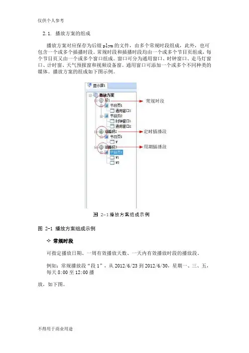
2.1. 播放方案的组成播放方案对应保存为后缀plym的文件,由多个常规时段组成,此外,也可包含一个或多个插播时段。
常规时段和插播时段均由一个或多个节目页组成,每个节目页又由一个或多个窗口组成。
窗口可分为通用窗口、时钟窗口、走马灯窗口、计时窗、天气预报窗和视频设备窗。
通用窗口可添加一个或多个不同种类的媒体。
播放方案的组成如下图示例。
图 2-1 播放方案组成示例常规时段可指定播放日期、一周有效播放天数、一天内有效播放时段的播放段。
例如:常规播放段“段1”,从2012/6/23到2012/6/30,星期一、三、五,每天8:00至12:00播放,如下图。
图 2-2常规播放段“段1”定时插播段在指定日期范围内的有效天内,指定时间点开始播放指定次数或时长的播放段;例如:定时插播段“插播段2”,从2012/6/23到2012/6/30,星期一、三、五,每天8:30开始播放10分钟,如下图所示。
图 2-3 定时插播段“插播段2”✧周期插播段在指定的日期范围、指定的有效天内、指定的时间段内,每隔一定时间播放指定次数或时长的播放段;例如:周期插播段“插播段3”,从2012/6/23到2012/6/30,星期一、三、五,12:00至18:00,每隔30分钟播放1次,如下图所示。
✧节目页计算机显示器屏幕上映射到LED显示屏的区域,用以实现可视的媒体数据(如视频、图像、字幕等)在LED显示屏上的显示播放。
可划分为多个显示区域,每个显示区域对应一个窗口。
●全局节目页:时段播放过程中,一直播放的节目页,可包含多个窗口。
全局节目页的播放窗口在播放时位于其它常规节目页的窗口前面。
在实际应用中,如果需要使用多种窗口布局的常规节目页,但又希望在固定位置一直显示时钟、天气预报、走马灯等媒体,可将该媒体编辑到全局节目页中;●常规节目页:常规节目页可包含多个窗口,每个常规节目页可有不同的窗口布局。
同一个播放时段可包含多个常规节目页。
多个常规节目页按从上到下的方式循环播放。
MCTRL R5User Manual Independent ControllerCopyright © 2018 Xi’an NovaStar Tech Co., Ltd. All Rights Reserved.No part of this document may be copied, reproduced, extracted or transmitted in any form or by any means without the prior written consent of Xi’an NovaStar Tech Co., Ltd.TrademarkStatementYou are welcome to use the product of Xi’an NovaStar Tech Co., Ltd. (hereinafter referred to as NovaStar). This document is intended to help you understand and use the product. For accuracy and reliability, NovaStar may mak e improvements and/or changes to this document at any time and without notice. Any problem in use or any good suggestion, please contact us through ways provided in the document. We willdo our utmost to solve the problems and adopt the suggestions after e v aluation as soon as possible.Change HistoryChange HistoryContentsContents Change History ................................................................................................................................ii1Safety ...............................................................................................................................................12Overview .........................................................................................................................................23Hardware Structure.......................................................................................................................33.1 Appearance .................................................................................................................................................. 33.2Dimensions ...................................................................................................................................... (5)4Homepage .......................................................................................................................................65Menu Operations ..........................................................................................................................85.1 BrightnessAdjustment (8)5.2 ScreenSettings ...........................................................................................................................................85.2.1 QuickConfiguration .................................................................................................................. (8)5.2.2 AdvancedConfiguration .................................................................................................................. (9)5.2.3 ImageOffset .............................................................................................................................. (9)5.3 RotationSettings (10)5.4 InputSettings .............................................................................................................................................105.4.1 Input Video SourceSettings (10)5.4.2 Input ResolutionSettings ........................................................................................................................105.5 DisplayControl ...........................................................................................................................................115.6 AdvancedSettings (11)5.6.1 MappingFunction ......................................................................................................................... (11)5.6.2 Loading CabinetFiles ..............................................................................................................................115.6.3 AlarmThreshold ....................................................................................................................... (12)5.6.4 Saving toHardware ........................................................................................................................ (12)5.6.5 Redundancy ................................................................................................................... (13)5.6.6 PresetTemplate ......................................................................................................................... (13)5.6.7 Hot Backup for InputSource (13)5.6.8 FactoryReset .............................................................................................................................. (13)5.6.9 Go Homepage(s) ...................................................................................................................................135.6.10 GreyscaleAdjustment ..................................................................................................................... (13)5.6.11 HardwareVersion ........................................................................................................................... (13)5.7 CommunicationSettings (13)5.8 Language ......................................................................................................................................... (14)Contents 6Specifications (15)Independent Controller MCRL R5User ManualCO.,LTD. 1 Safety1 Safety To avoid potential hazards, please use this product according to regulations. Poweroutlet should be installed near the unit and easy to reach. In the event of breakdowns,only trained personnel may disassemble it for maintenance, and please contact the after-sales department of NovaStar for help. High-voltage hazard: Operating voltage of this product ranges from 100 V to 240 V AC.Grounding: Ground connection of this product is enabled through power cords. Please make sure that ground conductors are in good condition.Electromagnetic interference: Keep this product far away from magnets, motors and transformers.Moisture proof: Keep this product in a dry and clean environment. In case of liquid immersion, please pull the power plug out immediately.Keep the product away from flammable and explosive hazardous Prevent liquids or metal fragments from dropping into the product in order to avoid accidents.substancesXI'ANIndependent Controller MCRL R5User Manual2Overview Developed by NovaStar, the MCTRL R5 is the first independent controller that supports rotation function. With up to 3840×1080@60Hz loading capacity of a single unit, it can support any custom resolution within this range as required, thus meeting the on-site configuration requirements of extra-long or extra-large LED displays. The MCTRL R5 supports HDMI, Dual Link DVI, SDI signal inputs, as well as 8 Neutrik Gigabit Ethernet ports, and 2 optical fiber outputs. The distinctive and innovative design of the MCTRL R5 enables screen configuration without PC, diverse image rotation effects, and amazing visual experience for users.Note: The device must be powered off before connection.To control multiple MCTRL R5 units (10 units at most), please cascade themaccording to the figure below.XI'ANNOVASTARTECHCO., LTD.Instruction on knob operations:On the home screen, pressing the knob enters the main menu.●On the main menu, rotating the knob selects a menu item or adjusts theparameter, and pressing the knob confirms the selection or enters the submenu.●Holding down the knob and BACK button simultaneously for 5 seconds locks orunlocks all the buttons.Rear PanelUser ManualNote: Type-A USB port is prohibited from being connected to the upper computer3.2 Dimension sUser Manual 3 Hardware StructureLTD.CO.,TECHUnit: mm NOVASTARXI'AN4 Homepage4 Homepage/ //CO.,TECHNOVASTARXI'ANIndependent Controller MCRL R5User Manual5 Menu Operations5Menu OperationsMCTRL R5 features powerful functions and simple operations. To achieve betterdisplay effects, users can choose to set other options in the menu.Brightness Adjustment5.1 On the main menu, press the knob to select the B rightness item and rotate the knobto adjust the brightness value.Screen Settings5.25.2.1 Quick ConfigurationBefore you start, load the cabinet configuration files and save them to the receiving card.Step 1 Press the knob to enter the main menu.Step 2 Choose Screen Settings > Q uick Config to enter the submenu, and rotate the knob to set corresponding options.● Set the row and column quantity of cabinets based on the actual condition of a screen.● Set the cabinet quantity connecting to port 1. There are limits on the loading capacity of ports. Refer to a ) in N ote for details. ●Set data flow of the screen, and refer to c ), d), a nd e ) in N ote for details.XI'ANNOVASTARTECHCO.,LTD.5.2.3 Image OffsetSet the horizontal offset and vertical offset of devices’ loading image.5.3 Rotation SettingsThere are 2 rotation methods: Port rotation and screen rotation.Port rotation: Rotation of cabinets loaded by an Ethernet port (For example, set the rotation angle of port 1, and the cabinets loaded by port 1 will rotate according to the angle).f). After enabling the rotation function, choose Screen Settings > Quick Config , and amessage asking “Disable rotation. Are you sure?” will appear. Choose Yes to continue.5.2.2 Step 1 Choose Advanced Config and press the knob to enter its submenu. Step 2 On the warning screen, click Yes to enter the advanced configuration screen. Step 3 Select Enable and set the parameters of targeted Ethernet ports.XI'ANNOVASTARRotate the knob to set the custom width (growing in even numbers), custom height, and custom refresh rate, and choose Apply . Press the knob to confirm the setting. If Apply is not enabled, the custom resolution is invalid.●Screen rotation: Rotation of the whole LED screen according to the rotationangle set before.Rotation settings:Step 1 Choose Rotation Settings > R otation Enable , and choose E NABLE . Step 2 Choose Port Rotate o r S creen Rotate and set parameters. Step 3 Select Save to save your settings.Notes:● Hardware screen configuration is required to be done before the rotation settings. ●After screen configuration are done on SmartLCT , set rotation function on MCTRL R5, and a message “ R econfig screen . Are you sure?” will appear. ChooseY es to perform rotation settings.Input Settings5.4 Input Video Source Settings5.4.1There are several types of input sources available for users to choose.5.4.2 Input Resolution Settings There are 2 methods to set input resolution: Method 1: Preset resolutionChoose a proper resolution from the preset standard resolutions, or use method 2 to customize the resolution. Method 2: Custom resolutionXI'ANNOVASTARTECHCO.,LTD.5.5 Display ControlNormal: P laying the input source normally.Black Out: T he screen is black out, with no display. Freeze: F reezing the displaying image.Test Pattern: 8 test patterns including pure color and lines testing.Image Settings: S etting red, green and blue brightness, color temperature, Gamma rate, and saving parameters.5.6 Advanced SettingsAdvanced settings include settings of multiple main functions, as shown below.5.6.1 Mapping FunctionWhen M apping Function is enabled, each of the cabinets will display the cabinetnumber and Ethernet port number it belongs to.5.6.2 Loading Cabinet FilesConnect to PC and start NovaLCT on PC, and import the saved cabinet configurationfiles.Step 1 Save cabinet configuration files.After configuring the receiving cards, click S ave to File to save the cabinet configuration files (.rcfgx) to local PC.XI'ANNOVASTARTECHCO.,LTD.Menu OperationsStep 2 Import the cabinet configuration files to the MCTRL R5.Note: After entering the C onfiguration File of Controller Cabinet Import window, NovaLCT will automatically read the configuration files already existed in the MCTRL R5. Users can change the names and orders of these files or delete them.Step 3 Load the cabinet configuration files.5.6.3 Alarm ThresholdSet the ranges of temperature and voltage values.XI'ANNOVASTARTECHCO.,LTD.5.6.4 Saving to HardwareSave all the configurations related to the receiving cards to the receiving cards and those data will not be lost even after the device is powered off.Menu Operations5.6.5 RedundancySet the current device as the primary or backup device.5.6.6 Preset TemplateSave configuration information, rotation parameters, and user settings information as5.6.7 Hot Backup for Input SourceSet backup source for the current input source. The backup source should be othertypes of input source supported by the device.5.6.8 Factory ResetReset the current device to factory settings.5.6.9 Go Homepage (s)The current page stays for how many seconds before going homepage when there is no actions.5.6.10 Greyscale Adjustment Adjust greyscale among the range from 4 to 15 for the LED display screen.Hardware Version5.6.11 View the hardware version of current device. In case of new version release, accessNovaLCT through PC to upgrade the hardware version. 5.7 Communication SettingsSet the communication mode and network parameters.Two communication modes are provided: U SB Preferred and L AN Preferred . When the USB and Ethernet ports are connected at the same time, the system will use the communication mode set by the user.XI'ANNOVASTARTECHCO.,LTD.templates. Users can add 10 templates at most.Menu Operations Network settings include manual mode and auto mode. When setting the network manually, the IP address of current device cannot conflict with IP addresses of other devices.5.8 LanguageChange the UI language of the MCTRL R5 unit.LTD.CO.,TECHNOVASTARXI'AN6Specifications6SpecificationsNOVASTARXI'AN。
奥玛执行器调试说明一、电气位置调节1、技术数据Comma nd sig nal (给定信号E1) 4-20mA(1-5V )mp4+ mp3-Feedback (反馈信号E2 实际值)4-20mA(1-5V)mp2+ mp1- 灵敏度(死区)△ E(P9)0.5%----2.5%低速时灵敏度“ sens”(P7)0.25%关延时“ t off ” P10 0.5-10S输入阻抗250欧2、关位置调整(正常状态)将执行器打到现场将执行器开到关限位输入4mA逆时针旋电位器p10到停位置测量E1(mp4+ mp3-)电压是否为1V测量E1(mp2+ mp1-)电压是否为1V,否则要调整当V28 (绿)和v27 (黄)均不亮时,顺时针调整p3(0)直到v27 (黄)发光当V28 (绿)亮时,顺时针调整p3 (0)直到v28 (绿)光灭,而v27 (黄)发光当v27 (黄)亮时,逆时针调整p3 (0)直到v27 (黄)光灭,然后而顺时针调整p3 (0)直到v27 (黄)发光3、开位置调整(正常状态)将执行器打到现场将执行器开到开限位输入20mA测量E1(mp4+ mp3-)电压是否为5V测量E2 (mp2+ mp1-)电压是否为5V,否则要调整当V28 (绿)和v27 (黄)均不亮时,逆时针调整p4(maX 直到v28 (绿)发光当V28 (绿)亮时,顺时针调整p4(maX直到v28 (绿)光灭,V28 (绿)发光当V27 (黄)亮时,逆时针调整p4 (maX直到v27 (黄)光灭,V28 (绿)发光4、开位置调整(反向控制)将开关1扳下将位置变送板上的接线7 (红)与5 (黑)对换接4mA当V28 (绿)和v27 (黄)均不亮时,顺时针调整p3 (0)直到v28 (绿)发光当V27 (黄)亮时,顺时针调整p3 (0)直到v27 (黄)光灭,V28 (绿)发光当V28 (绿)亮时,逆时针调整p3 (0)直到v28 (绿)光灭,然后而顺时针调整p3 (0)直到v28 (绿)发光5、关位置调整(反向控制)接20mA当V28 (绿)和v27 (黄)均不亮时,逆时针调整p4 (maR 直到v27 (黄)发光当V27 (黄)亮时,顺时针调整p4(maX直到v27 (黄)光灭,然后而逆时针调整p4 (maX直到v27 (黄)再发光当V28 (绿)亮时,逆时针调整p4 (maX直到v28 (绿)光灭,而V27 (黄)发光6、调节灵敏度将开关打到中控位置顺时针调节△ E (p9),灵敏度减小P10向左旋到位延时0.5s向右旋到位延时10s7、端子说明A2板(逻辑板)X1 11-12关力柜9--10关限位开限位3--4开力矩X0 1-2故障灯X3连接控制板A20的1*3端子,控制正反转继电器X4 连接电源板A8 1为24v,2为12v,3为0vA7板X8给定信号X7 1-2给定位置变送器提供24v电源Xk与中控连接2-3接给定,23--24接反馈35--36接阀门接点信号。
微电脑程序控制器操作手册在使用本控制器之前,请先确定控制器的输入输出范围和输入输出种类与您的需求是相符的。
1. 面板说明1.1 七段显示器PV:处理值(process value),红色4位显示SV:设定值(setting value),绿色4位显示1.2LEDOUT1 :第一组输出(Output1),绿色灯OUT2 :第二组输出(Output2),绿色灯AT :自动演算(Auto Tuning),黄色灯PRO :程式执行中(Program),黄色灯----- 只适用于PFY系列AL1 :第一组警报(Alarm 1),红色灯AL2 :第二组警报(Alarm 2),红色灯MAN :输出百分比手动调整(Manual),黄色灯※注意:当发生错误(Error)时,MAN灯会亮,并将输出百分比归零1.3 按键SET :设定键(写入设定值或切换模式):移位键(移动设定位数):增加键(设定值减1):减少键(设定值加1)A/M :自动(Auto)/手动(Manual)切换键。
自动:输出百分比由控制器内部演算决定手动:输出百分比由手动调整OUTL(在User Level中)决定2 自动演算功能(Auto tuning)2.2 需先将AT(在User Level中)设定为YES,启动自动演算功能。
2.3 自动演算结束后,控制器内部会自动产生一组新的PID参数取代原有的PID参数。
*自动演算适用于控温不准时,由控制器自行调整PID参数。
2.4 ATVL:自动演算偏移量(AutoTuning offset Value)SV减ATVL为自动演算设定点,设定ATVL可以避免自动演算时,因PV值震荡而超过设定点(Overshoot)。
例如:SV=200℃,ATVL=5,则自动演算设定点为195℃当自动演算中,PV值震荡,则是在195℃上下震荡,因此可避免PV值震荡超过200℃。
※注意:在PFY型号,,ATVL设定值即为自动演算设定点2.5 自动演算失败可能原因1:ATVL 设定值太大。
执行器控制主板调试及使用说明控制模块基本接线阀位电位器输入ΩmaxΩ3三线制点动控制辅助限位开关默认常开点接入24VDC-1A,120VAC-1A主控模块端子C1~C6电源输入,使用3组独立电源,CPU、模拟量输入、反馈输出电源完全隔离,供电端电源不正常,该处功能就会有问题,各组独立供电以提高整个系统间的信号干扰,没必要再使用信号隔离器。
控制模块端子排对于模拟量调节型基本功能控制执行器已连接至对外端子排,用户只需接线至对外端子排即可正常使用。
如需用执行器故障接点输出直接接至控制模块端子排B8、B9(故障时接通),如使用开关量控制模式(三线制点动控制),短接A0,A1,并在软件菜单A1中选Manual方式,不同供电接线方式如下:使用内部电源供电方式板子内部JP1跳线使用板内15V电源JP1JP1L、N为220V电源A4A3板子内部JP1跳线使用外部AC220V供电方式B14NLL24V+24V+24V-B13使用外部DC24V供电方式板子内部JP1跳线A3A4JP1COM COM(默认出厂跳线方式)二、面板设定器设定面板为液晶背光型,平时监视调节输入信号(用于4~20mA控制)、阀位反馈信号,故障时,按→键可查阅故障信息。
LED状态指示灯5个,RUN:运行灯,工作正常时闪亮,故障时常亮;MANU:本地手动或远控运行模式指示;AUTO:自动运行灯接受标准信号运行模式;R:正行,电制动瞬间闪亮;F:反行,电制动瞬间闪亮;操作按键5个,SET:设定参数、确认键;M/A:手/自动切换键;→键:移位键;↑键;设定数字增,上翻可选择项,手动开阀;↓键:设定数字减,下翻可选择项,手动关阀。
当按SET键或→键超过3秒则相当于复位键,设置若中途退出可复位。
若选用带红外遥控设定功能的执行器,遥控器操作面板设定方法同液晶屏设定面板,可实现接线后免开盖智能设定及操作维护,设定时请把红外遥控设定器对准玻璃窗口。
三、设定菜单密码:(默认555)按M/A键进入手动状态,按SET键,显示SET A菜单,再次按SET键,显示SET B菜单、SET C 菜单,依次循环;显示菜单项后按M/A键,进入密码显示555,用→键可移位,用↑↓键可修改。
诺瓦调试步骤(总6页) -CAL-FENGHAI.-(YICAI)-Company One1-CAL-本页仅作为文档封面,使用请直接删除诺瓦显示屏调试步骤一,调试前准备1,备件准备1)诺瓦面板2)诺瓦发送卡3)诺瓦接收卡4)诺瓦扁平线5)A-200-5电源6)HDMI转DVI线7)笔记本(带HDMI接口、USB口、WIFI)8)客户提供的无线路由器(含两根天线,底下有的接WIFI,底下无标识的接3G)、机顶盒(路由器和机顶盒上均贴有使用地点和IP地址)2,拷贝合同调试记录(嘉善调试人员提供)1)笔记本安装诺瓦发送卡串口驱动(光盘)安装完成后设备管理器中是应该能找到COMx2)安装诺瓦控制软件NovaLCT-Mars Setup二,调试步骤1,无线路由器天线接好,并把天线吸在显示屏顶部2,无线路由器LAN1口与机顶盒LAN口用网线连接好3,机顶盒USB口连接USB转串口,USB转串口另一端接串口继电器。
4,看路由器指示灯,上电后Power灯常亮,启动正常后Alarm灯(蓝)常亮,机顶盒在线后Online灯常亮(如果3G信号不稳定,可能该灯会过一会儿黑一下,属于正常现象)。
如果有问题,打清鹤工程师电话(负责人:王晓楠或业务员:刘成),让他们远程看一下机顶盒是否在线。
5,笔记本HDMI口连接发送卡DVI输入6,笔记本USB口连接发送卡USB口,此时设备管理器中是应该能找到COMX 7,电控柜内自动断路器打开。
打开屏幕电源具体开、关屏步骤如下:1)连接机顶盒。
可以通过网线直接接机顶盒,即笔记本网卡与机顶盒网口连接;注意笔记本与机顶盒需要在同一网段。
2)telnet到机顶盒,控制串口继电器。
现假设机顶盒的IP是将笔记本IP改为在一个网段telnet 回车,登录到工控机tangox login:输入rootPassword:zsyjm9 (密码输入时不显示,请盲打)tangox[~]# cd /home/app/imps/bin/回车(输入路径时可以先输入目录头字母再按tab键,自动补全。