B_型控制器――WTS_通讯模块使用手册_CN_1[1].0
- 格式:pdf
- 大小:438.32 KB
- 文档页数:13

感谢您使用本厂产品使用前请认真阅读产品使用说明书目录一、概况 (1)二、工作原理 (5)三、主要技术指标 (5)四、安装及使用 (5)五、注意事项 (10)六、附录Pt100工业铂电阻分度值表 (11)一、概况1、温度控制器根据沈阳变压器研究所制订的JB/T6302《变压器用压力式温度计》标准的命名如下:22、温度控制器根据JB/T9236《工业自动化仪表产品型号编制原则》的要求产品命名如下:2BWY(WTYK)系列温度控制器的成套性和适用性图一 系列温度控制器外形及安装尺寸B W Y (W T Y K )二、工作原理变压器温度控制器(以下简称温控器),主要由弹性元件、毛细管、温包和微动开关组成。
当温包受热时,温包内感温介质受热膨胀所产生的体积增量,通过毛细管传递到弹性元件上,使弹性元件产生一个位移,这个位移经机构放大后指示出被测温度并带动微动开关工作,从而控制冷却系统的投入或退出。
BWY(WTYK)-802A、803A温控器采用复合传感器技术,即仪表温包推动弹性元件的同时,能同步输出Pt100热电阻信号,此信号可远传到数百米以外的控制室,通过XMT数显温控仪同步显示并控制变压器油温。
也可通过数显仪表,将Pt100铂电阻信号转换成与计算机联网的直流标准信号(0~5)V、(1~5)V或(4~20)mA输出。
三、主要技术指标(一)BWY(WTYK)-802、803型1、正常工作条件:(-40~+55)℃2、测量范围:(-20~+80)℃(0~+100)℃(0~+120)℃(0~+150)℃3、指示精确度: 1.5级4、控制性能:①设定范围:全量程可调②设定精确度:±3℃③开关差: 6±2℃④额定功率: AC 250V/3A⑤标准设定值:802:K1=55℃; K2=80℃803:K1=55℃; K2=65℃ K3=80℃5、仪表安装尺寸:详见外形及安装尺寸图(二)BWY(WTYK)-802A、803A型1~5条同上。
WINCC连接Siemens PLC的经常使用方式之马矢奏春创作一.WINCC使用CP5611通讯卡通过MPI连接PLC2前提条件21.STEP 7 硬件组态22.装置CP5611通讯板卡33.添加驱动法式和系统参数设置34.设置Set PG/PC Interface35.添加通道与连接设置56.连接测试与通讯诊断6二.WINCC使用CP5611通讯卡通过PROFIBUS连接PLC8前提条件8I.STEP 7 硬件组态82.装置CP5611通讯板卡103.添加驱动法式和设置系统参数104.设置Set PG/PC Interface115.添加通道与连接设置146.连接测试与通讯诊断15三.WINCC使用普通网卡通过TCP/IP连接PLC16前提条件161.STEP7硬件组态162.设置IP地址与通讯检测183.添加驱动法式和设置系统参数194.设置Set PG/PC Interface205.添加通道与连接设置226.连接测试与通讯诊断23四.WINCC使用普通网卡通过Industrial Ethernet连接PLC25前提条件251.STEP7硬件组态262.添加驱动法式和设置系统参数273.设置Set PG/PC Interface284.添加通道与连接设置295.连接测试与通讯诊断31说明:1.文档并未列出所有的WINCC连接Siemens品牌PLC的所有方法,只是列举了一些经常使用的方法.2.在各种连接方式中的参数设置可能会略有分歧, 在此列出的步伐和参数只是一套可以连通的设置方法.一.WINCC使用CP5611通讯卡通过MPI连接PLC前提条件I)通过CP5611实现PLC系统与WINCC6.0通讯的前提条件是在装置有WINCC的计算机上装置CP5611通讯板卡.II)使用STEP7编程软件能够通过MPI正常连接PLC. 1.STEP 7 硬件组态STEP7设置MPI通讯, 具体步伐不在此详述, 可参考如下图1.1示:注意:1.新建一个MPI网络用来通讯, 设置MPI网络的地址和波特率, 且记住, 在随后的设置中需要匹配.2.装置CP5611通讯板卡装置CP5611, 并装置驱动法式, 具体CP5611的装置过程和注意事项可参考如下链接:3.添加驱动法式和系统参数设置翻开WINCC工程在Tag Management-->SIMATIC S7 PROTOCOL SUITE->MPI右键单击MPI, 在弹出菜单中点击System Parameter, 弹出System Parameter-MPI对话框, 选择Unit标签, 检查Logic device name(逻辑设备名称).默认装置后, 逻辑设备名为MPI如图1.3所示:图1.2图1.34.设置Set PG/PC Interface进入把持系统下的控制面板, 双击Set PG/PC Interface图标.在Access Point of the Application:的下拉列表中选择MPI (WINCC), 如图 1.4所示, 而后在Interface Parameter Assignment Used:的列表中, 点击CP5611(MPI), 而后在Access Point of the Application:的下拉列表中显示:MPI (WINCC)CP5611(MPI), 如图1.5所示:图1.4图1.5设置CP5611的通讯参数,点击Proerties….按钮, 弹出Properties-CP5611(MPI)属性对话框, 设置参数, 如图 1.6所示:重要的参数如下所示:Address:CP5611的地址(MPI地址必需唯一, 建议设置为0)Transmission Rate:MPI网络的传输速率(默认为187.5Kbps)您可以修改, 但必需和实际连接PLC的MPI端口的传输速率相同)Highest Station Address:MPI网络的最高站地址(必需和PLC的MPI网络参数设置相同)图1.6诊断MPI网络, 点击Diagnostic…按钮, 进入诊断对话框.如下图所示:Test按钮点击后, 显示OK暗示CP5611工作正常.点击“Read”按钮后, 将显示所有接入MPI网络中的设备的站地址, 如果只能读到自己的站地址, 此时, 请检查MPI网络和硬件连接设置, 只有胜利读取到CPU的站点地址, 才华进行以下的步伐, 否则, 不成能建立通讯.5.添加通道与连接设置添加驱动连接, 设置参数.翻开WINCC工程在Tag Management-->SIMATIC S7 PROTOCOL SUITE->MPI, 右键单击MPI, 在下拉菜单中, 点击New Driver Connection, 如图 1.7所示, 在弹出的Connection properties对话框中点击Properties按钮, 弹出Connection parameters-MPI属性对话框, 如图1.8所示:图1.7图1.8图1.9重要的参数如下所示:Station Address:MPI端口地址Rack Number:CPU所处机架号, 除特殊复杂使用的情况下, 一般填入0Slot Number:CPU所处的槽号注意:如果您是S7-300的PLC, 那么该参数为2, 如果是S7-400的PLC, 那么要根据STEP7项目中的Hardware软件检查PLC插在第几号槽内, 不能根据经验和物理装置位置来随便填写, 可能的参数为2、3、4(主要是依据电源的年夜小来决定)否则通讯不能建立.6.连接测试与通讯诊断通过WINCC工具中的通道诊断法式WinCC Channel Diagnosis即可测试通讯是否建立.注意:此时PLC必需处于运行状态, 老版本的PLC必需处于RUN-P或者RUN状态, WINCC必需激活运行, 根据图 1.9所示的位置, 进入通道诊断工具, 检测通讯是否胜利建立.如图 1.10所示, 绿色的“√”暗示通讯已经胜利建立.图1.10图1至此WINCC使用CP5611通讯卡通过MPI连接PLC的过程完毕.二.WINCC使用CP5611通讯卡通过PROFIBUS连接PLC前提条件1.通过CP5611实现PLC系统与WINCC6.0通讯的前提条件是在装置有WINCC的计算机上装置CP5611通讯板卡.2.将所要连接的PLC的端口设置为PROFIBUS通讯协议, 对MPI/DP类型的端口尤其重要.I.STEP 7 硬件组态使用STEP 7软件组态PLC的硬件信息, 将相应的板卡在Hardware进行硬件组态, 选择你将要连接WINCC的对应端口, 如果其类型为MPI/DP, 则需要将端口指定为PROFIBUS, 如下图2.1所示:点击上图所示的Properties…按钮, 如下图所示:A.设置该PROFIBUS端口的地址为2B.点击New按钮, 在Subnet下新建一个PROFIBUS网络, 在弹出的对话框中设置参数, 如图2.2所示:其中重要参数如下:Highest PROFIBUS Address:指整个PROFIBUS网络中的最高的站点地址, 默认为126, 可作修改.Transmission Rate:PROFIBUS网络的通讯速率, 整个网络中所有站点的通讯波特率应当一致.Profile:具体的传输协议的设置, 这里我们使用DP.其他设置可根据您项目的具体情况进行设置.2.装置CP5611通讯板卡装置CP5611, 并装置驱动法式, 具体CP5611的装置过程和注意事项可参考如下链接:3.添加驱动法式和设置系统参数翻开WINCC工程在Tag Management-->SIMATIC S7 PROTOCOL SUITE->PROFIBUS右键单击PROFIBUS, 在弹出菜单中点击System Parameter, 如图2.4所示, 弹出System Parameter- PROFIBUS对话框, 选择Unit 标签, 检查Logic device name(逻辑设备名称).默认装置后, 逻辑设备名为CP_L2_1:, 如图2.5所示:图2.4图2.54.设置Set PG/PC Interface进入Windows把持系统下的控制面板, 双击Set PG/PC Interface图标, 在Access Point of the Application:的下拉列表中选择CP_L2_1: 如图 2.6所示, 而后在Interface Parameter Assignment Used:的列表中, 点击CP5611(PROFIBUS), 而后在Access Point of the Application:的下拉列表中显示:CP_L2_1:CP5611(PROFIBUS), 如图2.7所示.图2.6图2.7设置CP5611的通讯参数,点击Proerties….按钮, 弹出Properties-CP5611(PROFIBUS)参数.如图2.8所示:重要的参数如下所示:Address:CP5611的PROFIBUS地址Transmission Rate:PROFIBUS网络的传输速率(您可以修改, 但必需和实际连接PLC的PROFIBUS端口的传输速率相同)Highest Station Address:PROFIBUS网络的最高站地址(必需和PLC的PROFIBUS网络参数设置相同)Profile:设置具体通讯协议, 这里使用DP图2.8诊断PROFIBUS网络, 点击Diagnostic…按钮, 进入诊断对话框.如下图所示:Test按钮点击后, 显示OK暗示CP5611工作正常.点击Read按钮后, 将显示所有接入PROFIBUS网络中的设备的站地址, 如果只能读到自己的站地址, 此时, 请检查PROFIBUS网络和硬件连接设置, 只有胜利读取到CPU的站点地址, 才华进行以下的步伐, 否则, 不成能建立通讯, 如图2.9所示:5.添加通道与连接设置添加驱动连接, 设置参数.翻开WINCC工程在Tag Management-->SIMATIC S7 PROTOCOL SUITE->PROFIBUS, 右键单击PROFIBUS, 在下拉菜单中, 点击New Driver Connection, 如图 2.10所示, 在弹出的Connection properties对话框中点击Properties按钮, 弹出Connection parameters-PROFIBUS属性对话框, 填入参数, 如图2.11所示:重要的参数如下所示:Station Address:(通讯模块的IP地址)Rack Number:CPU所处机架号, 除特殊复杂使用的情况下, 一般填入0Slot Number:CPU所处的槽号注意:如果您是S7-300的PLC, 那么该参数为2, 如果是S7-400的PLC, 那么要根据STEP7项目中的Hardware软件检查PLC插在第几号槽内, 不能根据经验和物理装置位置来随便填写, 可能的参数为2、3、4(主要是依据电源的年夜小来决定)否则通讯不能建立.6.连接测试与通讯诊断通过WINCC工具中的通道诊断法式WinCC Channel Diagnosis即可测试通讯是否建立.注意:此时PLC必需处于运行状态, 老版本的PLC必需处于RUN-P或者RUN状态, WINCC必需激活运行, 根据图2.12所示的位置, 进入通道诊断工具, 检测通讯是否胜利建立.如图 2.13所示, 绿色的“√”暗示通讯已经胜利建立.至此WINCC使用CP5611通讯卡通过PROFIBUS连接PLC的过程完毕.3.WINCC使用普通网卡通过TCP/IP连接PLC第四章前提条件通过以太网实现PLC系统与WINCC6.0通讯的前提条件是PLC 系统配备以太网模或者使用带有PN接口的PLC, 以太网模块列表如下表所示:注:只有支持ISO通讯协议的模块才支持(Industrial Ethernet 工业以太网)通讯, 具体情况可观察STEP7中的模块信息.本文档下列步伐应用CPU 315-2PN/DP型号的PLC, 使用普通以太网卡连接.组态过程1.STEP7硬件组态使用STEP7编程软件对PLC系统进行软件组态, 在Hardware 界面内拔出实际的PLC硬件, 如下图3.1所示:在PN-IO槽双击弹出PN-IO属性对话框, 如图3.2所示:点击图 3.2属性对话框, 弹出网络参数设置对话框, 如图3.3所示:点击New按钮, 新建一个工业以太网络, 输入该PN模块的IP address(IP地址)和Subnet mask(子网掩码), 在简单使用的情况下, 不启用网关.当您使用的是CPU+以太网模块通讯时, 双击以太网模块, 会自转动出以太网模块的属性信息, 设置以太网通讯模块的IP地址和子网掩码.方法与PN-IO的属性设置相同, 如下图所示:注意如果要使用TCPIP通讯方式, 必需启动IP Protocol being used, 设置IP地址与子网掩码, 如图3.4所示:将组态下载到CPU, 则PLC方面设置完成.对第一次使用以太网通讯, 必需保证首先使用MPI或者PROFIBUS的通讯方式, 将设置好参数的组态下载到目标PLC, 尔后即可通过以太网的方式进行法式监控和项目下载.2.设置IP地址与通讯检测设置装置有WINCC计算机的windows把持系统的TCP/IP参数, 将WINCC组态计算机的IP地址设置成为和PLC以太网通讯模块或者PN-IO的IP地址保证是一个网段, 注意子网掩码的设置, 如图3.5所示:通过在法式运行中键入CMD进入DOS界面, 使用网络命令PING测试以太网通讯是否建立, PING的命令如下:ping 目标IP 地址–参数如下图3.6所示:此例中, PN-IO的IP地址为192.168.0.100 子网掩码:255.255.255.0;组态计算机的IP地址为192.168.0.244 子网掩码:255.255.255.0, 此处显示暗示以太网通讯已经建立, 而且状态良好.注意:如果此处不能Ping通PLC的PN端口或者以太网模块, 则通讯不成能建立, 后面的步伐就不用进行了, 若要通讯胜利, 必需保证实际的物理以太网通讯坚持正常.3.添加驱动法式和设置系统参数翻开WINCC工程在Tag Management-->SIMATIC S7 PROTOCOL SUITE->TCPIP右键单击TCPIP, 在弹出菜单中点击System Parameter, , 如图3.7所示, 弹出System Parameter- TCPIP对话框, 选择Unit标签, 检查Logic device name(逻辑设备名称).默认装置后, 逻辑设备名为CP-TCPIP, 如图3.8所示:4.设置Set PG/PC Interface通讯接口设置, 进入把持系统控制面板, 双击Set PG/PC Interface, 在默认装置后, 在应用法式访问点是没有CP-TCPIP 的, 所以需要手动添加这个应用法式访问点, 如下图3.9所示:被选中<Add/Delete>后, 会弹出一个对话框, 如下图3.10所示:在如图 3.11的情况下, 在Interface Parameter Assignment Used:选择TCP/IP->实际网卡的名称, 设置完成后如图3.12所示:注意:1.您的网卡分歧, 显示会有分歧, 请确保所选条目为您正在使用的普通以太网卡的名称.2.这里使用的应用法式访问名称为CP-TCPIP, 因为在WINCC 装置胜利后, CP-TCPIP是TCPIP驱动法式下默认的名称, 所以在Set PG/PC Interface下我们添加此名称的访问点, 您同样可以使用其他名称, 但必需保证, 必需同时修改, 并坚持完全一致, 这样通讯同样可以实现.您可以点击Diagnostics按钮后, 您可以对该网卡进行诊断, 确保其正常工作, 如图3.13所示:5.添加通道与连接设置添加驱动连接, 设置参数.翻开WINCC工程在Tag Management-->SIMATIC S7 PROTOCOL SUITE->TCPIP, 右键单击TCPIP, 在下拉菜单中, 点击New Driver Connection, 如图3.14所示, 在弹出的Connection properties对话框中点击Properties按钮, 弹出Connection parameters- TCPIP属性对话框, 填入参数, 如图3.15所示:在弹出的对话框中输入STEP7中已经设置的PN-IO或者以太网模块的的IP地址和机架号和槽号.在弹出的Connection Properties中点击Properties按钮, 在弹出的Connection parameter中输入参数:IP Address:(通讯模块的IP地址)Rack Number:CPU所处机架号, 除特殊复杂使用的情况下, 一般填入0Slot Number:CPU所处的槽号注意:如果您是S7-300的PLC, 那么Slot Number的参数为2, 如果是S7-400的PLC, 那么要根据STEP7项目中的Hardware 软件检查PLC插在第几号槽内, 不能根据经验和物理装置位置来随便填写, 可能的参数为2、3、4(主要是依据电源的年夜小来决定)否则通讯不能建立.6.连接测试与通讯诊断通过WINCC工具中的通道诊断法式WinCC Channel Diagnosis即可测试通讯是否建立.注意:此时PLC必需处于运行状态, 老版本的PLC必需处于RUN-P或者RUN状态, WINCC必需激活运行, 根据图3.16所示的位置, 进入通道诊断工具, 检测通讯是否胜利建立.如图 3.17所示, 绿色的“√”暗示通讯已经胜利建立.至此WINCC使用普通以太网卡通过TCPIP连接PLC的过程完毕.四.WINCC使用普通网卡通过Industrial Ethernet连接PLC连接到第三章前提条件通过Industri al Ethernet工业以太网实现PLC系统与WINCC6.0通讯的前提条件是PLC系统配备以太网模或者使用带有PN接口的PLC, 以太网模块列表如下表所示:注:只有支持ISO通讯协议的模块才支持(Industrial Ethernet 工业以太网)通讯, 具体情况可观察STEP7中的模块信息.最简单的判断以太网模块是否支持Industrial Ethernet通讯的方式是, 在STEP7的硬件组态Hardware中是否具有MAC参数的填写的输入框, 如下图4.1所示:参考STEP 7软件中的产物硬件信息来判断以太网模块是否支持Industrial Ethernet工业以太网通讯, 如下图4.2所示:在通讯设置以前请确认模块支持Industrial Ethernet ISO通讯, 而后进行如下设置:本文档下列步伐应用CP443-1型号的以太网通讯模块, 使用普通以太网卡连接.组态过程1.STEP7硬件组态使用STEP7编程软件对PLC系统进行软件组态, 在Hardware 界面内拔出实际的PLC硬件, 在本例中使用了两块CP443-1通讯模块, WINCC使用CP443-1(1)和PLC进行通讯,如下图4.3所示:在CP343-1(1)通讯模块上双击, 会弹出Properties-CP443-1的属性对话框, 在对话框中点击Properties….按钮, 弹出属性对话框, 激活“Set MAC address/use ISO Protocol”, 在MAC address下设置通讯板卡的MAC地址, 如图4.4所示, 该地址可以在物理通讯板卡端口处标签上检查.点击New按钮, 新建一个工业以太网络, 在弹出的对话框都使用默认设置, 该步伐一定要做, 否则无法建立通讯.将组态编译, 下载到CPU, 则PLC方面设置完成.对第一次使用工业以太网通讯, 必需保证首先使用MPI或者PROFIBUS的通讯方式, 将设置好参数的组态下载到目标PLC, 尔后即可通过工业以太网的方式进行法式监控和项目下载.2.添加驱动法式和设置系统参数翻开WINCC工程在Tag Management-->SIMATIC S7 PROTOCOL SUITE->Industrial Ethernet, 右键单击Industrial Ethernet, 在弹出菜单中点击System Parameter, 如图 4.5所示, 弹出System Parameter- Industrial Ethernet对话框, 选择Unit标签, 检查Logic device name(逻辑设备名称).默认装置后, 逻辑设备名为CP_H1_1:如图4所示:3.设置Set PG/PC Interface通讯接口设置, 进入把持系统控制面板, 双击Set PG/PC Interface, 在下拉菜单中选择CP_H1_1:如图4.7所示:在如图 4.7所示的情况下, 在Interface Parameter Assignment Used:选择ISO Ind Ethernet->实际网卡的名称.注意:1.您的网卡分歧, 显示会有分歧, 请确保所选条目为您正在使用的普通以太网卡的名称.可以点击Diagnostics按钮后, 您可以对该网卡进行诊断, 确保其正常工作, 如图4.9所示:4.添加通道与连接设置添加驱动连接, 设置参数.翻开WINCC工程在Tag Management-->SIMATIC S7 PROTOCOL SUITE->Industrial Ethernet, 右键单击Industrial Ethernet, 在下拉菜单中, 点击New Driver Connection, 如图 4.10所示, 在弹出的Connection properties对话框中点击Properties按钮, 弹出Connection parameters- Industrial Ethernet属性对话框, 填入参数.在弹出的对话框中输入STEP7中已经设置的CP443-1通讯模块的MAC地址和机架号和槽号, 如图4.11所示:在弹出的Connection Properties中点击Properties按钮, 在弹出的Connection parameter中输入参数:Ethernet Address:(通讯模块的MAC地址)Rack Number:CPU所处机架号, 除特殊复杂使用的情况下, 一般填入0Slot Number:CPU所处的槽号注意:如果您是S7-300的PLC, 那么Slot Number的参数为2, 如果是S7-400的PLC, 那么要根据STEP7项目中的Hardware 软件检查PLC插在第几号槽内, 不能根据经验和物理装置位置来随便填写, 可能的参数为2、3、4(主要是依据电源的年夜小来决定)否则通讯不能建立.5.连接测试与通讯诊断通过WINCC工具中的通道诊断法式WinCC Channel Diagnosis即可测试通讯是否建立.注意:此时PLC必需处于运行状态, 老版本的PLC必需处于RUN-P或者RUN状态, WINCC必需激活运行, 根据图 1.9所示的位置, 进入通道诊断工具, 检测通创作时间:二零二一年六月三十日讯是否胜利建立.如图 4.13所示, 绿色的“√”暗示通讯已经胜利建立.至此WINCC使用普通以太网卡通过Industrial Ethernet连接PLC的过程完毕.创作时间:二零二一年六月三十日。

BHYW系列计量单元主板使用说明书唐山智能电子有限公司目 录1. 系统概述2. 安全及注意事项3. 各部分名称及功能4. 工作原理简介5. 安装调试6. 使用注意事项1.概述BHYW/BHYW-485/BHYW-DP水泥包装机计量控制单元主板(以下简称BHYW系列计量单元主板)适用于BHYW-xQT、BHYW-xEXET、BHYW-xFT、BHYW-xQ、BHYW-xEXE(x=6、8、10)系列回转式水泥包装机配套使用。
共有BHYW型、扩展RS-485接口的BHYW-485和扩展PROFIBUS-DP接口的BHYW-DP型三种型号。
具有计量精度高,运行稳定可靠,功能齐全,操作简便等突出特点,它非常适合在水泥厂恶劣的工作环境下连续运行。
本说明书主要描述BHYW 0-0030版本水泥包装机计量单元主板的功能、原理、使用及操作方法等内容。
1.1系统功能:1.1.1自动清零及净重控制功能:BHYW系列计量单元主板在卸袋后对空秤进行自动测量,自动跟踪修正零点。
也可以在插袋完成后进行自动清零,以实现水泥包净重精确计量控制。
1.1.2设定参数远程调整功能:BHYW系列计量单元主板设有操作键盘,操作人员可方便地进行参数设置和修改;同时,BHYW型产品配置RS-485接口的BHYW-485或是配有PROFIBUS-DP接口的BHYW-DP产品,还能通过总线在机下、中控室或是包装操作站对设定参数进行调整,读取系统数据进行破包率、产量等统计。
1.1.3开机自诊断及其它检测功能:BHYW系列计量单元主板具有开机自诊断功能,能对自身部分硬件故障进行诊断并对装入参数进行校验和报警,能对检测点动作、粗细流灌装状态及关闸板驱动进行显示,便于观察及维修。
当出现严重影响计量精度的故障时,自动输出关闸门信号禁止罐装操作。
1.1.4自测试功能:BHYW系列计量单元主板具有自测试功能,在自测试菜单下,通过菜单操作可以进行开关量输入及回路测试,全部输出控制动作及输出回路测试。
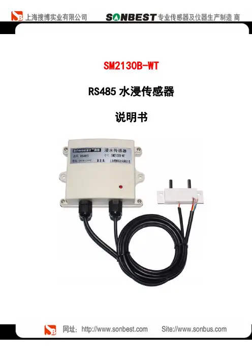
SM2130B-WT RS485水浸传感器说明书概述SM2130-WT漏水控制器是一款成本低廉的智能化液体泄漏检测设备,其输出信号包含继电器信号和 485信号。
不需要外加转换模块就可以轻松的与各种监控系统相整合,实现远程报警及远程设备的控制。
SM2130-WT漏水控制器可监控长达 200米的双芯漏液传感电缆。
它既可以和检测线缆安装使用,也可以和它其检测探头配套使用,一旦检测到液体,控制器立即启动继电器,输出常开常闭无源信号,可与其它集成采集主机联网使用。
该产品采用标准的 modbus-RTU 通信,方便与监控系统集成。
适用于检测机房基站、仓库、图书馆、博物馆和工业现场等重要场所的实时泄漏检测,更加可用于空气处理装置、冷冻机组、液体容器、泵槽等需要监测泄漏的设备。
特点与特色1. 敏感度高2. RS485 远距离通信接口,最远可达 1.2 公里3. 指令简单4. 6-24V 宽电源供电5. 高性价比技术参数及特点使用说明1.接线直接使用设备自带的引线,根据颜色提示进行接线2.安装尺寸3. 通讯协议设备所有操作或回复命令都为16进制数据。
默认通讯波特率:9600,8,n,1。
基本命令格式:[设备地址][功能码][起始地址:2字节][数据长度:2字节][CRC16校验]意义如下:A、设备地址:设备地址范围为1-249,其中250即0xFA为通用查询地址,当不知道设备地址时,可用此通用查询地址进行查询。
B、功能码:不同的应用需求功能码不同,比如3为查询输入寄存器数据。
C、起始地址:查询或操作寄存器起始地址。
D、数据长度:读取的长度。
E、CRC校验:CRC16校验,低位在前,高位在后。
1)读取数据(功能码为0x03 )[设备地址][03][起始地址:2字节][数据长度:2字节][CRC16校验]设备响应:[设备地址][命令号][返回的字节个数][数据1][CRC16校验]响应数据意义如下:A、返回的字节个数:表示数据的字节个数,也就是数据1,2...n中的n的值。

BW(S)T-PLC系列步进式无油电转可编程微机调速器说明书武汉四创自动控制技术有限责任公司目录第一章概述 (4)第二章系统结构 (5)2.1 系统结构框图 (5)2.2 框图说明 (5)2.3 系统工作原理 (6)第三章系统配置 (8)3.1 电气系统配置 (8)3.1.1 硬件配置 (8)3.1.2 软件基本配置 (9)3.1.3 功能增强软件配置 (9)3.1.4 调试设备及软件(不属于调速器设备内) (9)3.1.5 试验设备(不属于调速器设备内) (9)3.2 机械系统配置 (9)第四章主要功能及特点 (10)4.1 主要功能 (10)4.1.1 调节与控制功能 (10)4.1.2 诊断及容错功能 (11)4.1.3 开发调试功能 (12)4.2 主要特点 (12)第五章主要技术数据及性能指标 (13)5.1 主要技术数据 (13)5.2 主要性能指标 (14)第六章硬件构成 (15)6.1 PLC简介 (15)6.2 操作终端 (15)6.3 步进电机驱动模块 (16)6.4 步进电机 (20)第七章软件编程说明 (25)7.1 主程序流程框图 (25)7.2 调节模式 (26)7.3 开机、停机规律 (27)7.4 数字协联 (29)7.4.1 双调节水轮机的协联特性 (29)7.4.2 协联插值算法 (29)7.5 自动、手动运行及相互切换 (30)第八章面板说明 (31)8.1 机电分柜面板说明 (31)8.2 机电合柜面板说明 (31)第九章机械液压系统 (32)9.1 概述 (32)9.2 主要部件介绍 (33)第十章安装调试维护说明 (37)10.1 机械安装调试 (37)10.2 电气安装调试 (37)10.3 调速器的检修与维护 (41)第十一章运行操作说明 (45)11.1 调速器上电或复位 (45)11.2 模式切换 (45)11.3 增加、减少操作 (46)11.4 机械部分操作 (46)11.5 调速器运行操作 (46)第一章概述水轮机微机调速器是本世纪七十年代在电液调速器的基础上发展起来的新型水轮机调速器。
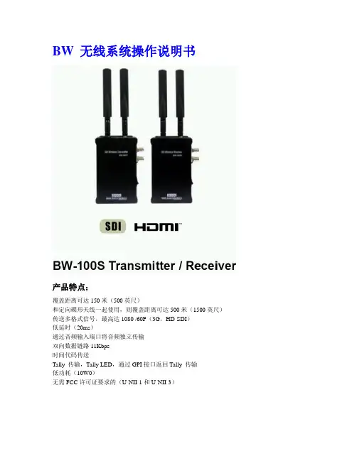
BW 无线系统操作说明书产品特点:覆盖距离可达150米(500英尺)和定向碟形天线一起使用,则覆盖距离可达500米(1500英尺)传送多格式信号,最高达1080 /60P(3G,HD-SDI)低延时(20ms)通过音频输入端口将音频独立传输双向数据链路11Kbps时间代码传送Tally 传输,Tally LED,通过GPI接口返回Tally 传输低功耗(10W0)无需FCC许可证要求的(U-NII-1和U-NII-3)部件说明1)V板适配器用于V型电池安装的内置V板,安顿保尔适配器可连接2)V-Mount适配器V-Mount适配器用于连接V-Mount电池,替代了DV Mount,双DV Mount,或安顿保尔适配器。
3)内置电源接口DV Mount连接此接口供电4)更新接口通过迷你USB gender.接口更新固件发射器侧面板左测面板1)环路输出SDI环通输入端口2)SDI输入支持SMPTE标准音频信号的HD/ SD SDI输入端口。
3)HDMI输入端口HDMI输入端口(有音频信号),请注意,某些数码单反相机不能通过外部端口发送音频信号。
4)电源开关5)Mini USB端口用于固件更新,更新前,用户可通过我们的服务代表获取帮助。
6)直流电源输入端口12V直流电源输入接口,7~30V也可用。
右侧面板1)配对按钮当发射机和接收机配对不成功,或使用不同型号的发射机和接收机时需按下此按钮,通常用户不需要按下此按钮。
2)Link LED指示灯发射器和接收器连接上成功,此灯亮起。
3)电源指示灯4)电池指示灯电池容量低,此灯闪烁5)Tally LED指示灯当Tally 控制被使用时,此灯亮起6)SDI/HDMI选择切换选择SDI或HDMI输入7)音频输入接口此端口接收立体声音频(例如来自麦克风)、从视频端口分离出来的输入音频。
8)远程端口此端口接收tally控制信号9)红外线遥控端口遥控接收端口接收器侧面板左侧面板1) SDI 输出接口12) SDI 输出接口23) HDMI 输出接口4) 电源开关5) Mini USB 端口特殊固件更新端口6)直流电源端口12V交流电源输入接口,7~30V也可用。
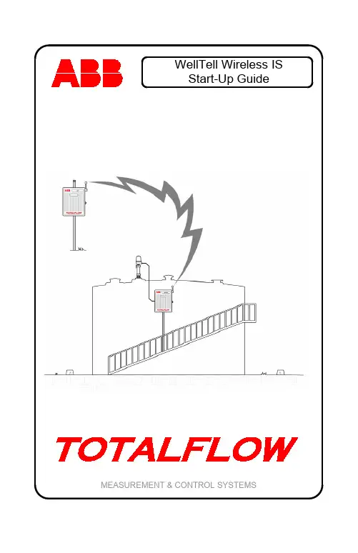
WellTell Wireless ISStart-Up Guide MEASUREMENT & CONTROL SYSTEMSIntellectual Property & Copyright Notice©2009 by ABB Inc., Totalflow Products (“Owner”), Bartlesville, Oklahoma 74006, U.S.A. All rights reserved.Any and all derivatives of, including translations thereof, shall remain the sole property of the Owner, regardless of any circumstances.The original US English version of this manual shall be deemed the only valid version. Translated versions, in any other language, shall be maintained as accurately as possible. Should any discrepancies exist, the US English version will be considered final. ABB is not liable for any errors and omissions in the translated materials.Notice: This publication is for information only. The contents are subject to change without notice and should not be construed as a commitment, representation, warranty, or guarantee of any method, product, or device by Owner.Inquiries regarding this manual should be addressed to ABB Inc., Totalflow Products, Technical Communications, 7051 Industrial Blvd., Bartlesville, Oklahoma 74006, U.S.A.1IntroductionFor installation in Classified Hazardous Locations: Please consult the User’s Manual, the drawing(s) referenced on the unit’s name plate, and any national and local codes of jurisdiction.This is a quick start guide designed for typical installations only. It is recommended that inexperienced technicians consult the Totalflow ® WellTell Wireless User’s Manual for more detailed information while doing the installation and start-up. Scan through the guide to see what information is available before beginning the installation. If there are questions that are not answered in this guide or other documentation, call a Totalflow representative or call the number listed on the back page of this guide.Unpack and inspect the WellTell-X and the WellTell-IS and any other optional equipment, if purchased. Inspect all parts and pieces for damage and missing or incorrect components.Before BeginningThe WellTell-IS system is comprised of two parts (see Figure 1): the host (WellTell-X) and the intrinsically safe (IS) barrier client (WellTell-IS). The host, WellTell-X, is generally installed in the site controller (XFC or XRC). The IS barrier client, WellTell-IS, is installed near the LevelMasterapplication.Figure 1. Basic Setup2Basic InstallationThe following information covers the initial installation of the WellTell-X host at the site controller (XFC/XRC), the installation of the WellTell-IS client near the LevelMaster application and the final application configuration and test at the site controller.The instructions are broken down into segments that cover the mechanical and electrical installation, along with the configuration of the system. It is assumed that this installation is taking place within either a 6400 or 6700 enclosure. Step 1 WellTell-IS Mechanical InstallationThe mechanical installation for both the WellTell-IS client and WellTell-X host is the same. Use the following instructions to accomplish the task. 1A Position pipe saddle on meter run. Select a location thatallows easy user access and is close to the equipment.Temporarily attach the saddle on the meter run pipe using U-bolt and associated hardware. 1B Screw 2” by 40” mounting pipe into saddle (see Figure 2).Place the level against pipe and vertically align. Adjust pipe,mounted in saddle, until vertical alignment is achieved. Aftervertical alignment, securely tighten 2” by 40” pipe in saddle.Tighten the saddle mounting bolts. Ascertain that the pipe issecurely installed in the saddle. 1CPosition enclosure on 2: mounting pipe and secure in placewith two U-bolts, flat washers, lock washers and two 9/16”bolts (see Figure 3).Figure 2. Pipe and Saddle Mount3Figure 3. Pipe Mounted 6400/6700 Enclosure Step 2 WellTell-X InstallationThe WellTell-X host unit is mounted in a communication tray (generally at the factory) and is designed to be installed in a Totalflow 6400 or 6700 enclosure (see Figure 4).At the top of the enclosure is the area where communication devices are installed. This area is referred to as the communication compartment (see Figure 5). All communication equipment is secured to the communication tray and slid into this compartment. The WellTell-X is mounted to standoffs on the communication tray and then slid into the communication compartment.4Figure 4. Communication TrayFigure 5. Communication Tray Installed in 6700 Enclosure5 Step 3 WellTell-X Host Communication WiringNOTE: If the unit came pre-configured from the factory, ignore thefollowing wiring instructions.Wiring of the WellTell-X host to a parent device (XFC/XRC) is fairly simple. In the example (see Figure 6), an XFC-195 board is used as the parent meter. If the application involves something other than the XFC-195, please check the meter pinouts before proceeding.Additionally, the following example uses COM 2 of the XFC. COM 1 is often defaulted for communication with a remote device (radio, modem, etc.). Wiring is simplified by the use of pre-wired cable (2100759-004)designed specifically for the WellTell-X device.Figure 6. Wireless Host Wired to COM 2 of XFC-195 Step 4 Configuring COM 2 for the LevelMaster ApplicationAfter completing the electrical wiring for the WellTell-X to COM 2 of the flow computer, the user needs to configure the COM 2 communication port.NOTE: In Figure 6, COM 2 (XA2) must have an RS-485 module(2015193-002) inserted.Figure 7 walks the user through the steps (A, B and C) to configure COM 2 for the LevelMaster application.6Figure 7. COM 2 Configuration for LevelMaster SetupWellTell-IS WiringElectrical wiring at the WellTell-IS (client) is done in two basic steps: powering the unit and wiring the RS-485 to the LevelMaster sticks. Step 5 WellTell-IS Client Electrical WiringThe WellTell-IS client can be mounted near or at the top of the storage tank. It should be mounted in a Division 2 or non-hazardous location. However, this can be a minimum of 10’ away from any opening (outside of the Division 1 areas), and a short piece of cable can be run to the LevelMaster itself.The WellTell-IS client also has an onboard battery charger to maintain the charge on a 12 VDC lead-acid battery. Figure 8 illustrates the most common way to provide power to the WellTell-IS.7Figure 8. Powering of the WellTell-IS Step 6Wiring the LevelMaster Sticks to the IS BarrierThe second part of the electrical installation for the WellTell-IS is the wiring of the LevelMaster sticks to the IS barrier on the WellTell-IS. Figure 9 illustrates how this is achieved.Figure 9. Wiring LevelMaster Sticks to the IS BarrierSystem ConfigurationStep 7Configuring WellTell-XIn a similar fashion to configuring the meters for the COM 2 port, the user must also configure the WellTell-X radio.To configure the WellTell-X (or the WellTell-IS) radio, the user must have the WellTell Wireless Utility (WWU) program and a typical 9-pin to 9-pin (male DB9 to female DB9) cable. The cable connects between a laptop and the maintenance connector of the WellTell-X.7A Configure WellTell-X Security.WWU supports two levels of access: Restricted Use andAdmin (lower left on the System Config tab). Restricted Usegives the user access to the basic setup parameters that aremost often used (i.e., Network ID, FR Channel, etc.). Lesserused parameters (i.e., Encryption Key, Range Refresh, etc.)are grayed out, if Restricted Use is used. Normal setup doesnot require Restricted Use. These lesser parameters can beaccessed through Admin. Admin is achieved by entering thepassword. The factory password is ‘0000.’As opposed to providing an in-depth, screen-by-screen explanation of the WWU utility, the opening screen is presented to the user along with references to the various available tabs that contain relevant parameters on each of their corresponding screens (see Figure 10).7B System Config Tab.Set the parameters as shown within Figure 10.7C Radio Config Tab.Parameter Field ValueMode ServerNetwork ID 1 (Must match Client)RF Channel Anything between 16 and 47 (must match Client)Baud Rate 9600Delivery Mode BroadcastRF Mode AcknowledgeDuplex Mode Half Duplex7D Network View Tab.Leave default values.8Figure 10. WWU Main Screen7E PC Port Tab.Parameter Field ValuePort COM 1 (Communication port of laptop PC)Baud Rate 9600Data Bits 7 bit for LevelMaster – Required for Snoop feature Parity Even – Required or Snoop featureStop Bits 1Tab.7F FlashLoaderLeave default values.Tab.7G TestLeave default values.9Step 8 Configuring WellTell-ISJust as the host radio, WellTell-X, was configured, it is necessary to configure the WellTell-IS client radio.As before, it is necessary to have the WWU program and a typical 9-pin to 9-pin (male DB9 to female DB9) cable. The cable connects between the laptop and the maintenance connector to the WellTell-IS.The opening screen for the WellTell-IS client radio is similar to the opening screen for the WellTell-X host, with the exception of a display that states that this is a Wireless Client Server as opposed to a Wireless Host Server.Rather than providing an in-depth, screen-by-screen explanation of the WWU, please refer to Figure 10 to view the available tabs. As presented in the previous section, the following details each individual tab available to the user and the corresponding parameter fields and values that must be entered therein.8A System Config Tab.Set the parameters as shown within Figure 10.8B Radio Config Tab.Parameter Field ValueMode ClientNetwork ID 1 (Must match HostRF Channel Anything between 16 and 47 (must match Host)Baud Rate 9600Delivery Mode BroadcastRF Mode AcknowledgeDuplex Mode Half Duplex8C Network View Tab.Leave default values.8D PC Port Tab.Parameter Field ValuePort COM 1 (Communication port of laptop PC)Baud Rate 9600Data Bits 7 bit for LevelMaster – Required for Snoop featureParity Even – Required or Snoop featureStop Bits 18E FlashTab.LoaderLeave default values.1011 8F Test Tab.Leave default values. Step 9 Final Configuration at the Site Controller (XFC/XRC)With the WellTell-X host and the WellTell-IS client both installed and configured, the last step is to configure the site controller (XFC/XRC at the host end) for the LevelMaster application. There is no difference in the configuration of the LevelMaster application due to the presence of the WellTell products. LevelMaster is instantiated and configured as it would be without the WellTell products.With the system up and running, the WellTell-X host display looks similarto Figure 11.Figure 11. WellTell-X (Host) DisplayThe antenna symbol is on. The “$” symbol is always active on the WellTell-X or host server. The “-“ is the system heart beat and blinks continuously. The blink slows down whenever the radio is dead or not connected. The “F3” in the upper right of the display denotes that this is a host server (WellTell-X). The main area of the display scrolls through several parameters: baud rate, temperature, channel, etc. For more information on the display, refer to the appropriate appendix.LCD Display and AnnunciatorsFigure 12. LCD DisplayDescription of Standard Displays (Annunciators)Envelope Indicates “Snoop” mode (i.e., processor is “snooping” thedata stream).Tx/Rx Indicates activity on the processor’s UART port.Antenna The Host Server (WellTell-X) annunciator is always on.The Client (WellTell-IS or WellTell-IO) is only on when theClient is ‘synced’ to a Host.Signal Strength A three section “progress bar” indicating incoming signalstrength between the Host and the Client.Battery Strength A four section “progress bar” indicating incoming signalstrength between the Host and the Client.Arrows The arrows represent up, down, left and right for a total offour. These arrows describe the Routing Matrix of theWellTell Product. This Routing Matrix connects themicroprocessor (also referred to as the Maintenance Port)to either the radio or to the RS485 device port. In PassThrough mode, the Device Port is connected directly tothe radio while the microprocessor can be enabled to“snoop” data from either the Device Port or the radio.More on this topic can be found in the WWU Help Files.When the UP arrow is on, the Microprocessor can snoopthe Device Port. If the UP arrow is not on, themicroprocessor can snoop the radio. Snoop is onlyoperational in Pass Though mode (i.e., the Left and Rightarrows are lit).The DOWN arrow being on informs the user that themicroprocessor is being connected in the Routing Matrix.When the RIGHT arrow is on, this depicts that the radio isbeing connected in the Routing Matrix.The LEFT arrow being on depicts that the Device Port(RS485) is being connected in the Routing Matrix.An example of the Routing Matrix might be having theDevice Port (RS485) connected directly to the radio (PassThrough mode). In this configuration the LEFT and RIGHTarrows would both be on.F1 – F5 Annunciators F1 I.S. Barrier Client indicator (WellTell-IS) F2 I/O Client indicator (WellTell-IO)F3 Host Server indictor (WellTell-X)F4 Reserved for future useF5 Test mode indicator[ ] Right and LeftBracketsIndicate activity on the Maintenance (processor) port. $ Always active on the Host and inactive on the Clients.M Activates whenever a cable is connected to theMaintenance port.- The ‘dash’ or ‘underscore’ is the system heartbeat. It12blinks off and on continuously. The blinking slowswhenever the Radio is dead or not connected.Description of Standard Displays (Alpha/Numeric Portion)SLEEP When power drops below 10.5VDC the Host Server willdetect the low voltage and enter a “SLEEP” mode.Host Server and the I/O and Barrier Clientb Ex: 9600 b Baud rate displayed in Numeric section.n Ex: n 1 Network ID displayed in Numeric section.ch Ex: ch 2 Channel displayed in Numeric section.b Ex: b 12.3 Battery voltage displayed in Numeric section.t Ex: t 72.1 Temperature displayed in Numeric section.I/O and Barrier Clients (Not Applicable to the Host Server)c Ex: c 0 Charger voltage.L Ex: L .5 Lithium cell voltage.Barrier Clients Only (Not Applicable to the Host Server or the I/O Client) o Ex: o .0 Overload voltage.i Ex: i .0 Intrinsically safe voltage.S Ex: S 4.5 Supply voltage supervisory.13ABB Inc.Totalflow Products7051 Industrial Blvd.Bartlesville, Oklahoma 74006Tel: USA (800) 442-3097International 001-918-338-4880。
TYWES模块使用说明VTYWE2S模块使用说明一术语定义配网操作:加入了WiFi模块的智能化产品,使用手机App(涂鸦智能)进行的几步操作。
最终手机、路由器、WiFi模块通过2.4G WiFi无线信号彼此建立通信后,用户可以在手机App上实现对智能化产品的现场及远程的操作和控制。
详细配网操作可参见《涂鸦智能APP使用说明》WiFi模块重置:带WiFi模块的智能化产品,当路由器名称变化或者产品转赠他人时,需要清除智能化产品里WiFi模块保存的当前路由器信息,因此需要将WiFi模块重置回出厂默认状态。
可以通过手机App、物理按键等方式实现WiFi模块的重置。
此操作也称“清除WiFi 模块配网信息”。
WiFi模块状态指示灯:配网和WiFi模块重置等操作的过程中指示WiFi模块当前工作状态的指示灯。
一般会有快速闪烁、慢速闪烁、常亮、常灭等状态来清晰的告知使用者WiFi模块或者智能化产品当前的工作状态。
WiFi模块重置按键:物理的实体按键,通过特定的触发方式将WiFi模块重置。
例如长按按键5秒的方式来完成WiFi模块的重置操作。
WiFi模块自处理:WiFi模块状态指示灯和WiFi重置按键都接在智能产品里的WiFi模块上,指示灯的状态、按键的检测等操作是由WiFi模块来完成。
然后WiFi模块通过串口告知用户MCU智能产品当前的工作状态。
功能简单的产品例如插座等就不需要用户MCU,直接由WiFi模块完成全部功能。
MCU与模块混合处理:WiFi模块状态指示灯和WiFi重置按键都接在智能产品里的用户MCU上。
指示灯的状态由WiFi模块告知MCU,按键的检测是由MCU来完成,智能产品当前的工作状态由MCU通过串口与WiFi模块通信后决定。
友情提示:本应用指导说明包含多种基于TYWE2S Wifi模块设计的智能产品Demo,例如智能独立插座、智能多路开关,智能排插等。
用户可根据自身需求及产品类型选择相应章节查看。
如产品是基于TYWE2S模块与用户MCU对接来完成,那么硬件设计时需要重点关注第二章《与MCU 通信连接说明》。
WTS-48模块 使用说明书首先,感谢您成为我司的顾客,并使用我司自主研发的WTS-48模块,您的选择是明智的。
我司是一家致力于开发和生产语音板块的专业厂家,拥有实力超群的研发团队和研制语音板块的扎实基础,以保证我们所发行产品的稳定性、优越性和专业性。
我司信奉顾客为上帝,为客户提供优质可靠的售后跟踪服务和技术支持,让顾客对我司产品的应用更为从容不迫得心应手。
不断更新的技术支持与优良的售后服务是我司一直屹立在语音板块市场上的主要因素之一。
为了使您更好的使用我们的产品,请您务必在使用之前详读说明书。
最后,再次感谢您选购和使用我司的高科技产品。
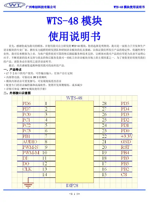
一、产品特点·17个I/O 口供用户使用,可作输出输入,任客户自行定制 ·内部带功放,可驱动0.5W/8欧喇叭·模块内部语音可重复擦写,可实现现场更改语音·配套专门的语音编程器和高端软件,使得开发周期缩短,成本减少 ·详情可参阅《WTV-S 模块使用手册》二、外部接口示意图三、管脚描述序号名称 功能描述 1 PD6 I/0 2 PD7 I/0 3 PC0 I/0 4 PC1 I/0 5 PC2 I/0 6 PC3 I/0 7 PB1 I/08 AUDIO 音频输出,接功放 9 PWM- 接0.5W/8欧喇叭 10 PWM-M 接0.5W/8欧喇叭11 DI 语音更新,ISP 下载数据输入口 12 DO 语音更新,ISP 下载数据输出口 13 CLK 语音下载时用到,时钟线14 GND 电源地 15 CS 片选信号,16 PB2 I/0 17 PB5 I/0 18 PB3 I/0 19 PB4 I/020 RST 模块外部复位信号输入21 GND 电源地 22 DC3.3V 直流电源3.3V23 PD0 I/0 24 PD1 I/0 25 PD2 I/0 26 PD3 I/0 27 PD4 I/0 28PD5I/0四、模块封装及尺寸:五、应用案例案例1共12路信号输入,其中1路为负脉冲信号触发,其余11路为低电平信号触发。
WBS系列一体化温度变送器安装使用说明书开封开仪自动化仪表有限公司1 概述WBS系列温度变送器(以下简称仪表)是我公司于国内首家研制出来,85年投放市场至今已历经20多年持续完善和改进的产品,在国内首先实现了传感器与变送电路一体化结构。
它以热电阻或热电偶作为温度敏感元件,采用专用电路模块,就地把敏感元件的信号转换成与温度呈线性的标准电流,用一般铜导线即可传输,不仅节少了贵重的补偿线或电缆,而且有信号传递失真小,抗干扰能力强,可进行远距离传输等优点。
能非常方便的与各种二次仪表或计算机系统配套,实现温度的测量与控制。
用途该仪表适用于工业领域,管道、容器中的介质温度,或其它气体、液体的温度、炉膛温度的检测。
防护类型a. 普通型:具有防水、防尘性能,可用于室内或室外安装,IP65。
b. 防爆型:经国家级仪器仪表防爆安全监督检验站(NEPSI)审查防爆安全性能符合、、标准规定的有关要求,防爆标志为 ExdⅡBT4~T6(隔爆型)合格证号GYB05673 ,ExiaⅡCT4~T6(本质安全型)合格证号 GYB05674本安型在防爆场合安装,需和经防爆检验站验单位认证的安全栅配套方可使用于现场存在ⅡC级以下的爆炸性气体混合物的场所。
仪表的指示方式a. 无指示:只输出与温度呈线性的标准电流。
b. 数字表头指示:除输出功能外,仪表还具有液晶数字显示器,指示当前所测温度值,指示单位℃。
c. 指针表头指示:除输出功能外,仪表用指针表头指示输出的电流信号值,指示量程的0~100%。
型号规格分类a. 型号分类(表1)表1b.2 主要技术参数量程与分度号(表2)注:与防爆产品接触的介质温度不能超过其温度组别的规定,见表3偏差参数:(1)基本误差:±%(用Pt100传感器)±%(用热电偶传感器)±% 协议定货(基本误差是传感器误差与转换电路误差的合成)(2)电源变化附加误差<%/10V(3)负载电阻变化附加误差:24V供电,负载从100Ω变到500Ω,输出变化<%。
WTR-S录音模块使用说明书首先,感谢您成为我司的顾客,并使用我司自主研发的WTR-S录音模块,您的选择是明智的。
我司是一家致力于开发和生产语音板块的专业厂家,拥有实力超群的研发团队和研制语音板块的扎实基础,以保证我们所发行产品的稳定性、优越性和专业性。
我司信奉顾客为上帝,为客户提供优质可靠的售后跟踪服务和技术支持,让顾客对我司产品的应用更为从容不迫得心应手。
不断更新的技术支持与优良的售后服务是我司一直屹立在语音板块市场上的主要因素之一。
为了使您更好的使用我们的产品,请您务必在使用之前详读说明书。
最后,再次感谢您选购和使用我司的高科技产品。
一、技术参数语音时间:从10秒至640秒电压范围:2.6V-3.3V静态工作电流<5mA工作电流:30-200mA二、电路示意图其中R1的大小及其对应的工作模式如下:R1 工作方式33K 串口62K 标准按键91K 一对一150K 并口+SBTR2的大小及其对应的采样率如下:R2 采样率33K 8K62K 12K91K 16K150K 22K在串口模式下,P05为CS线,P06为SCL线,P07为SDA线PCB板面图:三、管脚接线说明序号名称功能1 VCC DC2.6——3.3V,高于3.3V,有可能烧坏芯片2 GND 电源地3 P00 REC/K1/A04 P01 PLAY/PAUSE/K2/A15 P02 BACK/K3/A26 P03 NEXT/K4/A37 P04 STOP/K5/A48 P05 VOL-/K6/A5/CS9 P06 VOL+/K7/A6/SCLK10 P07 ERASE/K8/SBT/SDA11 P10 悬空12 P11 悬空13 P12 悬空14 P13 悬空15 P14 闪灯,外接LED16 P15 通过接不同阻值电阻,进行模式选择,17 P16 通过接不同阻值电阻,进行采样率选择18 P17 悬空19 RST 复位脚,低电平复位。
AS-i 3.0 profibus Gateways 操作手册陈意20111.the used symbols 略2.safty 略3.general information 略4.AS-I specification 3.0 略rmation about hazardous location 略6.连接,显示和按键在面板和不锈钢底板上有如下标识:●连接”AS-I Control Tools”时用于诊断的RS232接口●用于指示的状态的LED灯●9针脚的SUB-D转接口用作Profibus接口●显示器●调试用的按键●用于连接电源盒AS-i电路的端子6.1 单一的主站注意:这种方式下不允许将AS-i电源线或者例外一个主站连接到黄色的电缆线上。
不允许将从站或者中继器连接到hatched标记电缆线上。
6.1.1AS-I 3.0 Profibus Gateways的连接,适用的型号有BWU1567,BWU1599,BWU1653,BWU17736.1.2AS-I 3.0 Profibus Gateways的连接,适用于机型BWU18916.1.2.1地线的连接注意:地线端可以连接在地脚螺丝上也可以连接在端子上。
地线连接的时候尽量使用短的电线以确保有很好的电磁兼容性。
我们推荐使用的方法是通过连接地脚螺丝连接。
6.2双主站6.2.1 AS-i 3.0 Profibus Gateways的连接,适用的型号BWU1569,BWU1601,BWU1655注意:AS-i电路1和电路2是由单独的电源供电。
不允许将从站或者中继器连接到hatched标记电缆线上。
不允许将AS-i电源或者另外一个主站连接到黄色电缆线上。
6.2.1.1 地线的连接注意:地线端可以连接在地脚螺丝上也可以连接在端子上。
地线连接的时候尽量使用短的电线以确保有很好的电磁兼容性。
我们推荐使用的方法是通过连接地脚螺丝连接。
6.3双主站版本,一个电源和一个网关用在两个AS-i电路中6.3.1 AS-i 3.0 Profibus Gateways的连接,适用的型号BWU1569,BWU1601,BWU1655注意:AS-i电路1和电路2是由相同的电源供电的。
TDBYWT系列水轮机调速器使用维护说明书(PLC、步进电机、2.5/4.0MPa)目录1 简介 (1)1.1 TDBYWT系列调速器简介 (1)1.2 技术性能 (1)1.3 主要参数 (1)1.4 主要功能 (2)1.5 主要特点 (2)1.6 主要元器件硬件配置 (3)1.7 产品规格与技术数据 (4)2 电气部分 (5)2.1 可编程控制器主模块 (5)2.1.1 用途 (5)2.1.2 构成 (6)2.1.3 工作原理 (7)2.1.4 PLC的参数 (8)2.2 A/D转换模块 (9)2.2.1 用途 (9)2.2.2 状态指示灯 (10)2.2.3 参数 (10)2.3 D/A转换模块 (10)2.3.1 用途 (10)2.3.2 状态指示灯 (11)2.3.3 参数 (11)2.4 脉冲发生模块 (11)2.4.1 用途 (11)2.4.2 状态指示灯 (12)2.4.3 主要参数 (12)2.5信号处理模块 (12)2.5.1 用途 (12)2.5.2 工作原理 (14)2.6 步进电机驱动模块 (16)2.6.1 用途 (16)2.6.2 主要参数 (17)2.6.3 功能说明 (17)2.7 步进电机 (19)2.7.1 用途 (19)2.7.2 参数 (19)2.7.3 特点 (20)2.8 电源系统介绍 (20)2.9 面板仪表指示 (22)2.9.1 常规显示仪表 (22)2.9.2 按钮及指示灯 (22)2.10 PID调节的数学表达式 (29)3机械液压部分 (31)3.1 数字比例阀装置 (31)3.1.1 用途 (31)3.1.2 结构 (31)3.1.3 工作原理 (31)3.1.4 参数 (33)3.1.5 调整 (33)3.2 主配压阀 (33)3.2.1 用途 (33)3.2.2 结构 (33)3.2.3 工作原理 (34)3.2.4 参数 (35)3.3 分段关闭引导电磁阀 (35)3.3.1 用途 (36)3.3.2 结构 (36)3.3.3 工作原理 (36)3.3.4 参数 (36)3.4 事故电磁阀 (36)3.4.1 用途 (36)3.4.2 结构 (36)3.4.3 工作原理 (37)3.4.4 参数 (37)4 油压装置 (38)4.1 用途 (38)4.2 结构 (39)4.2.1 压力罐 (39)4.2.2 回油箱 (40)4.2.3 泵组及装配 (40)4.2.4 阀组及调整 (40)4.2.5 压力整定值 (41)4.2.6 自动化元件 (41)4.3 补气装置 (42)4.3.1 自动补气 (42)4.3.2 手动补气 (42)4.3.3 中间补气罐的自动补气 (42)4.4 油位计 (44)5 调速系统工作原理 (46)5.1 系统原理框图 (46)5.2 流程图 (47)5.3 调速器的工作过程 (54)5.3.1 自动开机 (54)5.3.2 空载运行 (54)5.3.4 自动停机 (55)5.3.5 事故停机 (55)5.3.6 自动运行切至手动运行 (55)5.3.7 手动运行切至自动运行 (55)6 调速器参数整定 (56)6.1 主配压阀中间位置的调整 (56)6.2 开启和关闭时间的调整 (56)6.3 接力器全关位置指示调整 (56)6.4 接力器全开位置指示调整 (56)7调速器试验 (57)7.1 厂内试验 (57)7.2 电站现场静水试验 (57)7.2.1 开机 (57)7.2.2 增减负荷 (57)7.2.3 解列 (57)7.2.4 正常停机 (57)7.2.5 事故停机 (57)7.2.6 自动/手动切换试验 (57)7.2.7 调速器静特性及转速死区测定试验 (58)7.3 电站现场动水试验 (58)7.3.1 手动开机及手动空载工况机组频率摆动值测定 (58)7.3.2 空载扰动 (58)7.3.3 自动工况下机组频率摆动值测定 (58)7.3.4 自动开机 (58)7.3.5 甩负荷试验 (58)7.3.6 七十二小时运行试验 (58)8 故障处理 (59)9 调速器的维护与运行注意事项 (62)10 型号编制说明 (63)11 装箱附图 (63)1 简介1.1 TDBYWT系列调速器简介TDBYWT系列调速器是我所研制的适用于中小型水轮机组的新一代调速器系列产品。