熔断器和断路器的比较
- 格式:ppt
- 大小:8.57 MB
- 文档页数:17

Data Bulletin0600DB06012/2007 Cedar Rapids, IA, USAA Comparison of Circuit Breakers and Fuses forLow-Voltage ApplicationsTony Parsons, PhD, P.E.,Square D / Schneider Electric Power Systems EngineeringI. Introduction Recent claims by fuse manufacturers regarding the arc-flash and simplified-coordination benefits of fuses do not tell the entire story regarding whichtype of device is “best” for a given power system. In reality, not only doesthe wide range of available circuit breaker types allow them to besuccessfully used on nearly any kind of power system, they can be appliedso as to provide selective coordination, arc-flash protection, advancedmonitoring and control features, all in a renewable device. This paper givesa feature-by-feature comparison of the merits of circuit breakers vs. fuses,discussing the relative merits of fuses and circuit breakers in each section.While both circuit breakers and fuses are available for application insystems that operate at higher voltage levels, the focus of this guide is onlow-voltage systems operating at 600 V or below.II. Basic Definitions and Requirements Article 240 of the National Electrical Code® (NEC) [1] provides the basic requirements for overcurrent (i.e., overload, short-circuit, and/or ground fault) protection in a power system. Special requirements for overcurrent protection of certain types of equipment are also contained in other articles—for example, details on protection requirements for motors and motor circuits are given in Article 430, while transformer protection requirements are given in Article 450.The NEC defines the two basic types of Overcurrent Protective Devices (OCPDs):fuse—An overcurrent protective device with a circuit-opening fusible part that is heated and severed by the passage of overcurrent through it.circuit breaker—A device designed to open and close a circuit bynonautomatic means and to open the circuit automatically on apredetermined overcurrent without damage to itself when properlyapplied within its rating.The NEC also requires that circuits be provided with a disconnecting means, defined as “a device, or group of devices, or other means by which the conductors of a circuit can be disconnected from their source of supply.” Since fuses are designed to open only when subjected to an overcurrent, they generally are applied in conjunction with a separate disconnecting means (NEC 240.40 requires this in many situations), typically some form of a disconnect switch. Since circuit breakers are designed to open and close under manual operation as well as in response to an overcurrent, a separate disconnecting means is not required.Both fuses and circuit breakers are available in a variety of sizes, ratings, and with differing features and characteristics that allow the designer of an electrical system to choose a device that is appropriate for the system under consideration.Data Bulletin2/2007Low-voltage fuses are available in sizes from fractions of an amp tothousands of amps, at voltage ratings up to 600 V, and with short-circuitinterrupting ratings of 200 kA or more. Fuses are inherently single-poledevices (i.e., an individual fuse can only operate to open one phase of amulti-phase circuit), but two or three individual fuses can be applied togetherin a disconnect to protect a multi-phase system. Low-voltage fuses aretested and rated according to the UL 248 series of standards. Several typescan be classified as current-limiting, which per the NEC definition meansthat they “...reduce the current flowing in the faulted circuit to a magnitudesubstantially less than that obtainable in the same circuit if the device werereplaced with a solid conductor having comparable impedance.” In otherwords, the current-limiting fuses open very quickly (within 1/2 cycle) in thepresence of a high-level fault, allowing them to provide excellent protectionfor distribution system components or load equipment. Fuses can beapplied in equipment such as panelboards, switchboards, motor controlcenters (MCCs), disconnect switches/safety switches, equipment controlpanels, etc.Circuit breakers are also available with a wide range of ratings—10 A tothousands of amps, also with short-circuit interrupting ratings to 200 kA—and are available as 1, 2, 3, or 4-pole devices. The three basic types of LVcircuit breakers are the molded-case circuit breaker (MCCB), low-voltagepower circuit breaker (LVPCB), and insulated-case circuit breaker (ICCB).MCCBs are rated per UL 489, have all internal parts completely enclosed ina molded case of insulating material that is not designed to be opened(which means that the circuit breaker is not field maintainable), and can beapplied in panelboards, switchboards, MCCs, equipment control panels,and as stand-alone disconnects inside a separate enclosure. LVPCBs,which are rated per ANSI standards and are applied in low-voltage drawoutswitchgear, are larger, more rugged devices that may be designed to befully field maintainable. ICCBs can be thought of as a “cross” betweenMCCBs and LVPCBs—they are tested per UL 489 but may share somecharacteristics with LVPCBs, including two-step stored energy mechanismavailability in drawout construction and partial field maintainability [2].Both types of OCPDs can meet the basic requirements of the NEC, but arecircuit breakers or fuses best suited for a particular application?Unfortunately, there is no simple answer to this question—several otherfactors must be taken into account, such as the level of protection providedby the OCPD, selective coordination requirements, reliability, renewability,and flexibility. The remainder of this guide will provide a discussion of eachof these topics.III. System Protection As discussed above, both circuit breakers and fuses meet the basic NECrequirements for overcurrent protection of electric power distributionsystems and equipment. Any type of OCPD must be sized and installedcorrectly after taking all derating factors and other considerations intoaccount. Particularly for overloads and phase faults, both circuit breakersand fuses provide excellent protection and either is suitable for mostapplications. A bit more consideration is warranted for some other aspectsof system protection, as discussed in the remainder of this section.A. Ground-Fault Protection Conventional wisdom states that the most common type of fault in a powersystem (by far) is a single-phase-to-ground fault. On solidly-grounded powersystems, the available ground-fault current level can be significant. In somesituations, ground fault current levels that are even higher than themaximum three-phase fault current level are theoretically possible.However, many ground faults produce only relatively low levels of faultcurrent due to impedance in the fault path (due to arcing or to some other2/2007Data Bulletinsource of impedance from phase to ground). While such faults can causesignificant equipment and facility damage if not cleared from the systemquickly, phase overcurrent protective devices may not respond quickly tothe lower fault levels—if they detect the fault at all. For example, an 800 Aground fault might simply appear as an unbalanced load to a 4000 A fuse orcircuit breaker not equipped with ground-fault protection. Because of this,NEC 230.95 requires supplementary ground-fault protection on servicedisconnects rated 1000 A or more on solidly-grounded, wye systemsoperating at more than 150 V to ground but not more than 600 V phase-to-phase (e.g., 277/480 V systems). The NEC also defines special ground-faultprotection requirements for health care facilities and emergency systems.See the appropriate NEC articles for more details.Circuit breakers can be equipped with integral ground-fault protectionthrough addition of either electronic trip units that act as protective relayingto detect the ground fault and initiate a trip, or through addition of add-onground-fault protection modules. Ground-fault trip units typically use thecurrent sensors internal to the circuit breaker to detect the ground faultcondition, though an external neutral sensor is normally required to monitorcurrent flowing on the neutral conductor in a 4-wire system. If desired,external relaying and current transformers (CTs) can also be used forground-fault detection provided that the circuit breaker is equipped with ashunt trip accessory that can be actuated by the external relay.By themselves, fuses cannot provide ground-fault protection except forrelatively high-level ground faults. When ground-fault protection is requiredin a fusible system, the disconnecting means (usually a switch, sometimes acontactor) must be capable of tripping automatically, and external relayingand a zero-sequence CT or set of residually-connected phase CTs must beinstalled to detect the ground faults and send the trip signal to thedisconnecting means.While either system can function well if installed properly, extra care mustbe taken with a fusible system (or circuit breaker-based system withexternal ground relaying) to ensure that all external sensors are orientedcorrectly and that all sensor and relay wiring is installed correctly.Performance testing of the ground-fault system, as required in NEC230.95(C) when the system is installed, should allow for identification of anyinstallation issues.B. Device Interrupting Ratings NEC 110.9 states that “equipment intended to interrupt current at faultlevels shall have an interrupting rating sufficient for the nominal circuitvoltage and the current that is available at the line terminals of theequipment.” Protective devices that are inadequately rated for either thesystem voltage or available fault current levels present a safety hazard, asthere is no guarantee that they will be able to interrupt faults withoutdamage either to themselves or to other equipment in the system. Thiscould result in extended downtime and present a significant fire hazard.Several types of low-voltage fuses (class R, class J, etc.) carry interruptingratings of 200 kA or more at up to 600 V. This is typically high enough tointerrupt even the most severe fault in the “stiffest” system. In addition, sincefuses are single-pole devices, their single-pole interrupting capability equalsthe full rating of the fuse. Note that the withstand rating of the equipment(e.g., panelboards, switchboards) in which fuses are applied may notalways be equal to the ratings of the fuses themselves—equipmentmanufacturers should be consulted, particularly when system fault currentsexceed 100 kA. Note also that some LV fuses have interrupting ratings aslow as 10 kA, so care should always be taken to ensure that fuses selectedare appropriate for the installation.Data Bulletin2/2007Circuit breakers of all types are also available with interrupting ratings up to200 kA. In the not-too-distant past, fused circuit breakers were required toachieve the 200 kA interrupting ratings, but modern circuit breakers canachieve this rating without fuses. Circuit breakers with lower ratings are alsoavailable, typically at a lower cost. Circuit breakers have single-poleinterrupting ratings that are adequate for installation on the majority of powersystems, though special consideration may be required in some cases. See[3] for additional information.C. Motor Protection Overcurrent Protective Devices (OCPDs) in motor circuits have a relativelydifficult job to perform. They must not trip on motor inrush current, but shouldbe sensitive enough to provide both overload protection and short-circuitprotection to the motor and its associated branch circuit. In many cases, thefuse/circuit breaker (or motor circuit protector—MCP which is essentially amolded-case circuit breaker with no overload element), is oversized toaccommodate motor inrush current and a separate overload relay is addedthat will open the motor contactor during overload conditions. These twodevices then combine to provide overload and short-circuit protection for themotor circuit.Motors can also be damaged by conditions other than short-circuits andoverloads. On three-phase systems, one of the most problematic abnormalconditions is system voltage unbalance, which can cause an increase inphase currents and create high negative-sequence currents that flow in themotor windings. Both of these cause increased heating in the motorwindings, which can cause insulation degradation or breakdown that canultimately result in failure of the motor. Unbalance from system sources suchas unbalanced load in a facility or voltage unbalance on the utility system ispotentially problematic whether circuit breakers or fuses are used as motorOCPDs. However, the use of fuses has the potential to produce a severeunbalance condition commonly referred to as single-phasing.Single-phasing occurs when one phase in a three-phase motor circuit opensbut the other two phases remain in service. If the single-phasing occursupstream of the motor but at the same voltage level, then zero current flowson the phase with the open fuse and elevated current levels flow in one orboth of the remaining phases, depending on whether the motor is wye ordelta-connected. Single-phasing on the primary side of a transformer feedingthe motor can produce elevated currents in all three phases, with two beingslightly elevated and the third current roughly double that of the other two.To help guard against motor damage or failure due to single-phasing:•Use a circuit breaker-based protection system. If properly maintained, allthree phases of a circuit breaker will open in response to a fault or overload,so single-phasing in the facility will be far less likely to occur. However, notethat if the utility supply is protected by fuses, this possibility still exists.•Apply phase-failure or current unbalance relaying, either at the facility main(in smaller installations) or at high-value loads (e.g., larger motors that aremore expensive to replace, critical loads where the downtime associatedwith a motor failure cannot be tolerated, etc.)•Size motor circuit fuses closer to the full-load current rating of the motor.One fuse manufacturer recommends sizing dual-element, time-delay fusesat 100–125% of the motor's actual load level (not the nameplate rating) toprovide better levels of protection against damage resulting from single-phasing [4]. Note that this does not eliminate the possibility of single-phasingoccurring, and could increase the possibility of nuisance fuse operation onsustained overloads. In applications where loading on a particular motorvaries widely, or in new facilities where actual current draw of a motor maynot be known, sizing the fuses properly could be a challenge. Application ofexternal relaying at high-value loads may still be warranted.2/2007Data Bulletin D. Component Protection One of the great advantages of a current-limiting overcurrent protectivedevice is that it can literally limit the peak magnitude of fault current thatflows through it by opening within the first half-cycle after fault initiation,before the fault current has a chance to reach its peak value. This helpsprovide a degree of protection for downstream equipment that couldotherwise be damaged by the magnetic or thermal effects produced by thehigh-level faults. Several types of low-voltage fuses are current-limiting toone degree or another. Highly current-limiting fuses for special applications,such as semiconductor fuses that are designed to protect power electronicequipment, are also available. Same is true of breakers, only that fuses areoften more current-limiting.Current-limiting molded-case circuit breakers are also available in a rangeof sizes and with interrupting ratings of 200 kA. As with current-limitingfuses, these circuit breakers are tested to determine the peak-let-throughcurrent (i p) and let-through energy (i2t). While these circuit breakers are notas current-limiting as the faster-acting current-limiting fuses (e.g., class J orclass RK-1), they do provide a degree of protection beyond that of a non-current-limiting circuit breaker or fuse, and may be appropriate for manyapplications.Proper protection, whether of conductors, motors, or other equipment,depends on OCPDs being applied appropriately. This includes ensuring thatdevices are sized properly and that they are installed on systems wherenone of the equipment ratings are violated.To help prevent misapplication of fuses, NEC 240.60(B) requires thatfuseholders are designed to make it difficult to insert fuses intended forapplication on higher amperage or lower voltage circuits. Additionally,fuseholders intended for current-limiting fuses should reject insertion of anon-current-limiting fuse.Switchboards and panelboards where circuit breakers are applied do nottypically have rejection features that prevent installation of a circuit breakerthat is of a compatible frame type but that has a lower interrupting rating.Realistically, any device can be improperly applied—and improper use ofprotective devices is an application issue, not an equipment issue. In the“real world”, inadequately-rated circuit breakers can be installed, fuses of agiven cartridge size but of a higher ampere rating can be installed into arejection fuseholder, fuses can be replaced with “slugs” (produced by themanufacturer or of the “homemade” variety), or fuseholders or circuitbreakers can be jumpered out altogether by a “creative” electrician with arelatively short length of wire. Proper selection, installation, andmaintenance of all OCPDs are all key requirements in providing goodsystem protection.Data Bulletin2/2007 E. Arc-Flash Protection With the increased interest in arc-flash hazards in recent years, the ability ofOCPDs to provide protection against arcing faults has received muchinterest. The potential severity of an arc-flash event at a given location in apower system depends primarily on the available fault current, the distanceof the worker away from the source of the arc, and the time that it takes theupstream OCPD to clear the arcing fault from the system. In many cases,little can be done about the first two factors—the available fault currentlevels depend on utility system contribution, transformer impedance values,etc.; while the working distance is limited by the fact that a worker workingon a piece of equipment must, in most cases, be physically close to theequipment.Proper selection and application of OCPDs can have a great deal of impacton the fault clearing time. Clearing the fault more quickly can provide a greatdeal of protection for workers, as the available incident energy is directlyproportional to the duration of the arcing fault—i.e., the incident energy canbe cut in half if the fault can be cleared twice as quickly. Equationsappearing in IEEE Standard 1584-2002 [5] provide the present “state-of-the-art” methods for determining the arc-flash hazard levels in a system andfor evaluating the impact of potential arc-flash mitigation options.For low-voltage systems, which OCPDs provide the best protection againstarc flash?•Circuit breakers, with adjustable trip units that can be set to strike abalance between providing selective coordination and arc-flashprotection?•Current-limiting fuses, which can clear high-level faults very quickly andminimize damage to both equipment and personnel?Unfortunately, there is no simple answer to this question, despite claimsmade by manufacturers of both types of OCPDs. In some cases, both circuitbreakers and fuses provide excellent protection. There are situations whencircuit breakers can perform better than fuses, and there are situationswhere fuses can perform better than circuit breakers. And there aresituations where neither circuit breakers nor fuses provide much arc-flashprotection at all, requiring either use of other means of protection(alternative system designs, installing systems that allow for remoteoperation of equipment, etc.) or a total prohibition of work on or nearenergized parts.When evaluating OCPDs in terms of the arc-flash protection that they mayprovide, three general principles are important to consider:•Evaluate specific devices when possible•Evaluate devices at the actual system fault current levels•Evaluate adjustable-trip circuit breakers at their chosen settings Evaluate Specific Devices The IEEE 1584 standard contains three basic calculation models that canbe used to determine arc-flash hazard levels—an empirically-derived,general model; simplified equations based on testing of current-limiting(class RK-1 and class L) low-voltage fuses; and simplified equations basedon calculations performed on “typical” low-voltage circuit breakers. Thegeneral equations require information on available fault current levels in thesystem as well as knowledge of the trip characteristics of OCPDs in thecircuit, but can provide accurate results for any type of OCPD and for a widerange of system conditions. The simplified circuit breaker and fuseequations require little to no knowledge of actual device trip characteristics,but differences in the way these equations were developed mean that theyshould not be used to conduct a direct “apples-to-apples” comparison ofspecific protective devices.2/2007Data BulletinAs discussed above, the simplified fuse equations are based on field testingof specific types of fuses, the simplified circuit breaker equations are basedon classes of circuit breakers and on the assumption that the relevant tripsettings are maximized, and not on specific devices or actual trip settings.The circuit breaker equations are meant to allow calculation of the “worst-case” arc-flash levels allowed by any example of a circuit breaker within agiven class—e.g., 100–400 A MCCBs. If the IEEE 1584 empirical equationsare used to calculate arc-flash levels downstream of such a circuit breaker,the values should never be higher than (and in many cases will be wellbelow) those shown by the simplified circuit breaker equations. This isparticularly true when using the equations to analyze larger LVPCBs—thesimplified IEEE 1584 equations assume that the circuit breaker'sinstantaneous and/or short-time pickup and delay settings are set to themaximum levels, which can result in the calculation of very conservativearc-flash levels if the circuit breakers are actually set differently. Forexample, Figure1 shows the incident energy levels vs. bolted fault currentvalues for 2000 A circuit breakers in a 480 V, solidly-grounded system.Figure1:Incident Energy vs. Bolted Fault Current for 2000 A CircuitBreaker’s Simplified Equations vs. Actual DataThe “LVPCB w/ST” and “LVPCB w/INST” curves are based on the IEEE1584 simplified equations for low-voltage power circuit breakers with short-time and instantaneous pickup, respectively. The “NW-L” and “NW-LF”curves show arc-flash values based on actual devices (2000 A Masterpact®NW-L and NW-LF circuit breakers set to trip instantaneously for an arcingfault, respectively).As shown in the plot, the simplified equations (particularly for the “LVPCBw/ST” curve) are well above the results calculated based on the actualdevice characteristics. When possible, a comparison of the level of arc-flashprotection a given device can provide, should be based on actual devicecharacteristics, not generic equations.Data Bulletin2/2007 What is the system fault current range?Current-limiting fuses can provide excellent protection and reduce theavailable incident energy downstream to minimal levels . . . as long as theyare operating within their current-limiting range. For lower fault currentlevels, the arc-flash levels can elevate.Thermal-magnetic MCCBs can provide excellent protection as long as theytrip instantaneously, but arc-flash levels can escalate for low-level faults thatrequire operation of the thermal element to clear the arc. For higher levels offault current, RK-1 and L fuses tend to allow a lower level of incident energythan a similarly-sized circuit breaker, but both devices provide an excellentlevel of protection—allowing for the use of Category 0 PPE in many cases.For example, see Figure2, which shows incident energy levels vs. boltedfault current for a 400 A Square D® LH circuit breaker, a 400 A Square D LCcircuit breaker, and a 400 A class RK-1 low-voltage fuse. The circuitbreakers are assumed to trip instantaneously.Figure2:Incident Energy vs. Bolted Fault Current for 400 A CircuitBreakers and 400 A Class RK-1 Fuses.As shown in Figure2, the relative performance of the circuit breakers isbetter for low-level faults, while the incident energy allowed by the fuses islower for higher fault current levels. However, the incident energy levels foreach device over the entire range of fault currents considered is less than2.0 cal/cm2 —the maximum level allowed for Category 0 PPE [6], indicatingthat both circuit breakers and fuses provide excellent protection.For larger devices, the relative performance of circuit breakers and fusesfollows these same guidelines, though the impact can be quite a bit larger.See Figure3, which shows the incident energy levels allowed by 1600 AClass L current-limiting fuses, as well as two varieties of 1600 AMasterpact® NW circuit breakers. Again, the circuit breakers are assumed totrip instantaneously for an arcing fault so circuit breaker settings must beconsidered, (see “Consider Circuit Breaker Settings” below), but this doesshow that 1600 A circuit breakers can perform significantly better than fusesfor systems with relatively low available fault current levels.2/2007Data BulletinFigure3:Incident Energy Comparison for 1600 A Protective DevicesConsider Circuit Breaker Settings For circuit breakers with adjustable trip settings, proper selection of settinglevels is important for both arc-flash protection and for system coordination.The best protection will be provided when the circuit breakers can be set totrip instantaneously. Little to no protection may be provided by a circuitbreaker when the settings are blindly set to maximum, as is sometimesdone after a “nuisance trip” of the device. Arc-flash studies can beperformed to determine optimum settings for circuit breakers and otherdevices in a system, but even then, it may not be possible to reduce circuitbreaker settings below a certain level to provide additional arc-flashprotection if system coordination is to be maintained.However, an adjustable circuit breaker still gives the flexibility to provide arc-flash protection in such situations, if only on a temporary basis. Forexample, the instantaneous pickup level of a circuit breaker feeding an MCCcan be turned down to the minimum setting when workers are present at theMCC, then turned back up when work is complete. This could allow thecircuit breaker to trip instantaneously and provide the best possible level ofprotection at the MCC when workers are present and exposed to thehazard, while the normal setting allows for proper coordination duringnormal operation. While this can provide an obvious benefit, it also has itsdrawbacks, including:•Requirement for analysis to determine to what level the circuit breakersettings should be reduced to provide additional protection, as well as whatlevel of protection is actually provided.•Uncertainty over how to provide arc-flash warning labels for such alocation—should labels show the available incident energy and requiredPPE with the “normal” circuit breaker settings, the reduced settings, orboth?•Temporary loss of selectivity can become semi-permanent if the circuitbreaker settings are not restored to normal when work is complete.While a full discussion of issues surrounding arc-flash hazards and theirmitigation is beyond the scope of this paper, many other references areavailable which discuss the subject in more depth, including [7] and [8].。


断路器、隔离开关、负荷开关、熔断器的区别在电气领域中,断路器、隔离开关、负荷开关和熔断器是常见的设备,用于保护电路和电气设备。
尽管它们的主要目标是保护电路免受过载和短路等故障的影响,但它们在操作原理和应用范围上存在一些差异。
本文将介绍这些设备的区别。
断路器断路器是一种自动的电气保护设备,用于保护电气回路免受过电流和过热的影响。
它能在电路中检测到故障发生时迅速切断电源,以防止过电流引起火灾或其它损坏。
断路器通常由一个电磁铁和一些释放机构组成,使其能够自动打开电路并切断电源。
断路器有不同的额定电流和断路容量,以适应不同电路的需求。
当电流超过断路器的额定电流时,电磁铁会触发释放机构,将断路器打开切断电源。
断路器还可以进行手动操作,以实现对电路的控制。
隔离开关隔离开关,又称为刀开关,是一种用于隔离电路的电气开关。
与断路器不同,隔离开关只负责将电路与电源隔离,无法在故障发生时自动切断电源。
它常用于维修或检修电气设备前,将设备与电源隔离,以确保工作人员的安全。
隔离开关通常采用带有可拆卸手柄的单刀、双刀结构。
手柄的拔出使接线柱与电源断开,从而隔离电路。
隔离开关的额定电压和额定电流必须与电路相匹配。
负荷开关负荷开关是一种主要用于手动控制电路的开关。
它具有开和闭的功能,可以手动操作以打开或关闭电路。
负荷开关适用于低压电力系统,用于分配和控制电流。
负荷开关通常由一个可手动操作的开关机构和一个电流传感器组成。
通过手动操作开关机构,可以打开或关闭电路。
负荷开关的电流传感器可以实时监测电流情况,并在超过额定电流时触发保护装置进行切断。
熔断器熔断器是一种过电流保护设备,广泛应用于电气回路中。
它可以根据电路中的电流大小进行自动断开。
熔断器的主要部分是一个熔断体,当电流超过额定值时,熔断体会因过热而熔断,切断电路。
熔断器有不同的额定电流和断路容量,以适应不同电路的需求。
当电流超过熔断器的额定电流时,熔断体会迅速熔断,并打开电路。
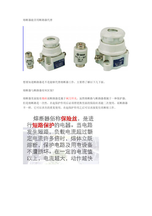
熔断器能否用断路器代替想要知道断路器是不是能够代替熔断器工作,主要得了解以下几下面。
熔断器与断路器有何区别?熔断器里面装有熔丝而断路器是属于闸刀开关,虽然熔断路与断路器都属于一种保护器,但是熔断路是一次性,在起保护作用后必须得更换里面的保险丝再能二次使用,而断路器不一样,它可以多次的重复使用,在起保护作用之后可以直接复位再断续工作。
熔断路与断路器的作用?断路器的界线划分的比较模糊,使用范围一般分为高压断路器与低压断路器,一般我们通常将3kv以上的电压称之为高压电器,而低压断路器又称之为自动开关,它是一种既具有手动开关的作用,还具有自动进行失压、欠压、过载和短路保护装置的电器。
而断路器又分为万能式断路器与塑壳式断路器。
断路器还可用来分配电能,不频繁地启动异步电动机,对电源的线路及电动机等实行保护作用,当它们发生严重的过载或者短路及欠压等故障情况下能够自动切断电路,其功能相当于熔断器式开关与过欠热继电器等的组合。
而且在分断故障电流后一般不需要变更零部件,一获得了广泛的应用。
断路器也可以实现线路的短路和过载保护,不过原理不一样,它是通过电流底磁效应(电磁脱扣器)实现断路保护,通过电流的热效应实现过载保护(不是熔断,多不用更换器件)。
而熔断器是通过电流保护电器熔断器是根据电流超过规定值一定时间后,以熔断器自身产生的热量促使熔体熔化,从而使电路断开的原理制成的一种电流保护器,熔断器一般广泛应用于低压配电系统和控制系统及用电设备中,作为短路和过电流保护,是应用最普遍的保护器件之一。
所以,断路器是能够代替熔断器工作的,只要能够保证熔断路与断路器二者之间的额定工作电流与额定分断电流一样便可。
但是倘若要把断路器当作熔断器作用的话,是不是有些大材小用的感觉?。

熔断器断路器都是一种电路保护器熔断器主要由熔体和熔管以及外加填料等部分组成。
使用时,将熔断器串联于被保护电路中,当被保护电路的电流超过规定值,并经过一定时间后,由熔体自身产生的热量熔断熔体,使电路断开,从而起到保护的作用。
熔断器以金属导体作为熔体而分断电路的电器,串联于电路中,当过载或短路电流通过熔体时,熔体自身将发热而熔断,从而对电力系统、各种电工设备以及家用电器都起到了一定的保护作用。
具有反时延特性,当过载电流小时,熔断时间长;过载电流大时,熔断时间短。
因此,在一定过载电流范围内至电流恢复正常,熔断器不会熔断,可以继续使用。
熔断器主要由熔体、外壳和支座3 部分组成,其中熔体是控制熔断特性的关键元件。
断路器按其使用范围分为高压断路器和低压断路器,高低压界线划分比较模糊,一般将3kV以上的称为高压电器。
低压断路器又称自动开关,俗称"空气开关"也是指低压断路器,它是一种既有手动开关作用,又能自动进行失压、欠压、过载、和短路保护的电器。
它可用来分配电能,不频繁地启动异步电动机,对电源线路及电动机等实行保护,当它们发生严重的过载或者短路及欠压等故障时能自动切断电路,其功能相当于熔断器式开关与过欠热继电器等的组合。
而且在分断故障电流后一般不需要变更零部件,已获得了广泛的应用。
1 熔断器(1) 熔断器的主要优点和特点①选择性好。
上下级熔断器的熔断体额定电流只要符合国标和IEC标准规定的过电流选择比为1.6:1 的要求,即上级熔断体额定电流不小于下级的该值的1.6 倍,就视为上下级能有选择性切断故障电流;②限流特性好,分断能力高;③相对尺寸较小;④价格较便宜。
(2) 熔断器的主要缺点和弱点①故障熔断后必须更换熔断体;②保护功能单一,只有一段过电流反时限特性,过载、短路和接地故障都用此防护;③发生一相熔断时,对三相电动机将导致两相运转的不良后果,当然可用带发报警信号的熔断器予以弥补,一相熔断可断开三相;④不能实现遥控,需要与电动刀开关、开关组合才有可能。
低压熔断器和断路器的比较和应用低压熔断器和断路器是电力系统中常见的两种电气保护设备。
它们的作用是在电路中出现过载、短路等故障时,自动切断电路,保护电器设备及人身安全。
在实际应用中,熔断器和断路器都有其各自的优点和特点,需要根据具体的电力系统结构、负载特点、设备要求等多方面因素选择使用。
首先,简单介绍一下低压熔断器和断路器的基本原理和特点:1. 低压熔断器:低压熔断器是一种保护电路的装置,它采用金属导体引线作为熔丝,当电路中过载或短路时,熔丝被加热,熔断丝的熔断量可以根据负载电流和断路时间来选择。
低压熔断器有以下特点:简单、可靠、价格低廉。
它适用于额定电压低于1000V、额定电流小于1000A的电路保护。
2. 断路器:断路器是一种主动式保护器件,它不同于熔断器的是,它可以在保护电路后主动恢复电路。
当电路中发生过载或短路时,断路器会及时切断电流,避免设备及线路的损坏。
并且,断路器除了过载及短路保护外,还具有欠电压、过电压、地故障等多种保护功能。
断路器有以下特点:能够及时切断电路,对电气设备的保护更加完全。
断路器适用于电流高、电压大、频繁开关、需要多重保护等场合。
接下来,对低压熔断器和断路器进行比较:1. 保护功能:低压熔断器只具有过载、短路保护功能,而断路器不仅具有过载和短路保护,还可实现过电流、过电压、欠电压、地故障等多项保护功能。
2. 切断能力:断路器的切断能力比熔断器强,可以实现大电流切断和频繁开关,可以满足高电压大电流、高频次开关的电路保护要求。
3. 使用寿命:熔断器的使用寿命比断路器要短。
由于熔丝在保护电路后需要更换,所以使用寿命受到熔丝的耐久程度的限制,而断路器则不需要更换内部零件,使用寿命较长。
4. 安全系数:熔断器相对于断路器来说,具有较低的安全系数。
在熔断器保护电路的过程中,如果熔丝被损坏或热量不均匀,可能导致保护失败,而断路器则在保护电路的过程中具有更高的可靠性和安全性。
最后,对低压熔断器和断路器在实际应用中的使用进行简述:低压熔断器适用于电气负载电流小、额定电压低的场合,如办公楼、商场等室内配电系统。


低压断路器和低压熔断器的选用及比较低压配电系统通常采用低压断路器和熔断器作短路保护,尽管两者在作短路保护的功能是相同的,但它们在使用上也有很大区别和不同,电气工程技术人员应该了解并掌握它们的选择和使用上的差异。
一、低压断路器低压断路器(LowV oltageCircuitBreakers)又称之为自动空气开关或空气断路器,是一种不仅可以接通和分断正常负荷电流和过负荷电流,还可以接通和分断短路电流的低压开关电器。
低压断路器在电路中除起控制作用外,还具有一定的保护功能,如过负荷、短路、欠压等保护功能。
它可用来分配电能、不频繁地启动电动机,对电源线路及电动机等实行保护,当供电回路发生严重的过载、短路及欠压等故障时能自动切断电路,其功能相当于熔断器式开关与过欠热继电器等组合。
低压断路器在分断故障电流后一般不需要更换其内部零部件,使用方便,已广泛应用于交直流低压配电系统各级馈出线,各种机械设备的电源控制和用电终端的控制和保护,包括用于不频繁地起动电动机及操作转换电路中。
1.低压断路器的分类低压断路器的分类方式较多,通常分为以下几种:(1)按交直流系统的不同,分为低压交流断路器和低压直流断路器。
(2)按灭弧介质分,有空气式和真空式,但目前使用的多为空气式低压断路器。
(3)按使用类别分,无选择型(保护装置参数不可调)和有选择型(保护装置参数可调)两类:A类:在短路情况下,断路器无明确指明用作串联在负载侧的另一短路保护装置的选择性保护,即在短路情况下,无选择性保护所需要的人为短延时,因而无短时耐受电流要求。
B类:在短路情况下,断路器明确指明用作串联在负载侧的另一短路保护装置的选择性保护,即在短路情况下,可实现选择性保护,有人为短延时(可调节),因而有短时耐受电流要求。
(4)按结构型式分框架断路器(ACB:AirCircuitBreakers):也称万能式断路器,将所有的零部件都安装在一个绝缘的或金属的框架上,有较多的结构变化、较多种的脱扣器、较多数量的辅助触头,一般选择性断路器,特别是大容量断路器,多设计成框架断路器。

熔断器和断路器的单位符号熔断器是用于保护电路免受过载或短路损坏的自动装置,它通常由熔丝或其他导热设备和相应的绝缘夹套等部件组成。
熔断器的单位符号是“F”,表示“固定”,此时熔断器的形状是固定的。
熔断器的主要参数就是它的熔断电流,它是衡量一只熔断器能够容忍的最大电流值。
一般熔断器的熔断电流比较标准的有1A、2A、4A、6A、8A、10A......32A等等。
二、断路器断路器是一种用于保护电路免受短路或过载损坏的自动元件。
它通常由基本元件(如铁芯,端子,动作机构等)和外壳组成,内部的组件可以识别当电流越界或超过额定值时断开被保护的电路。
断路器的单位符号是“CB”,表示“断路器”,此时断路器的形状可以是固定型也可以是插入型。
断路器的主要参数就是断开能力,插入型断路器其断开能力可以达到2.5KA、4KA、6KA、10KA、15KA等等。
三、熔断器和断路器的比较在使用上,熔断器和断路器有着很大的不同,首先,熔断器只能用于保护电路免受过载损害,而断路器可以用于保护电路免受过载,短路和过载损害。
其次,熔断器的参数是熔断电流,而断路器的参数是断开能力。
四、安装要求熔断器和断路器的安装要求是相同的,即要将它们装到一个具有适当的绝缘和支撑力的安装架上,并且要保证电源的稳定性。
此外,在安装过程中,要保持电缆的整洁度,避免电缆过紧或松动,以及避免接触和损坏电缆芯线。
此外,安装完成后,还要定期检查电缆的状况,以及检查安装设备,确保操作安全可靠。
五、维护服务熔断器和断路器在安装完成后,要定期检查其运行状态。
如果发现有熔断或断开的情况,要及时检查电路,确定问题的原因,如发现有超出熔断或断开能力的情况,要尽快修改电路,并及时更换坏掉的熔断器或断路器。
六、总结以上就是熔断器和断路器的单位符号、设备参数、安装要求及维护服务内容。
熔断器和断路器在电路保护中起着重要的作用,所以在安装时一定要仔细,并配有专业的维护服务,以确保电路的安全和可靠性。

1.隔离开关: 隔离开关具有明显断开点,不能分断电流,作为检修时分断电路使用。
隔离开关是一种没有灭弧装置的开关设备,主要用来断开无负荷电流的电路,隔离电源,在分闸状态时有明显的断开点,以保证其他电气设备的安全检修。
在合闸状态时能可靠地通过正常负荷电流及短路故障电流。
因它没有专门的灭弧装置,不能切断负荷电流及短路电流。
因此,隔离开关只能在电路已被断路器断开的情况下才能进行操作,严禁带负荷操作,以免造成严重的设备和人身事故。
只有电压互感器、避雷器、励磁电流不超过2A 的空载变压器,电流不超过5A 的空载线路,才能用隔离开关进行直接操作。
刀闸与隔离开关不同。
断路器:断路器用于接通和分断电路,能断开短路电流,作为短路保护和过载保护元件,可以理解为具有灭弧装置,可以带负荷断开电路的隔离开关。
断路器可用来分配电能,不频繁地启动异步电动机,对电源线路及电动机等实行保护,当它们发生严重的过载或者短路及欠压等故障时能自动切断电路,其功能相当于熔断器式开关与过欠热继电器等的组合。
空气开关为断路器的一种,以空气作为绝缘介质的断路器。
熔断器:熔断器是指当电流超过规定值时,以本身产生的热量使熔体熔断,断开电路的一种电器。
俗称的保险丝。
漏电保护器:漏电保护器,简称漏电开关,又叫漏电断路器,主要是用来在设备发生漏电故障时以及对有致命危险的人身触电保护,具有过载和短路保护功能,可用来保护线路或电动机的过载和短路。
常见的配电箱里电器装置,首先知道是什么,为什么要装这种装置,安装完后怎么做才能起作用。
弄懂这三点,自然就弄懂了配电箱。
刀闸和隔离开关同属刀型开关。
无论外形、结构原理、操作方法都很相似。
但它们有截然不同之点,必须严格区分。
刀闸是一种最简单的开关电器,用于开断500伏以下电路,它只能手动操作。
由于电路开断时常有电弧,所以,装有灭弧装置或快断触头。
为了增大灭弧能力,其刀一般都较短。
隔离开关有高压、低压、单极、三极、室内、室外之分,它没有专门的灭弧装置,不能用来接通、切断负荷电流和短路电流,只能在电气线路切断的情况下,才能进行操作。

浅析低压配电线系统中断路器与熔断器的对比发表时间:2018-10-24T15:50:48.750Z 来源:《防护工程》2018年第12期作者:谢辉军[导读] 比较低压断路器和熔断器各自的优缺点,做到保护电器在低压配电系统中的合理选择。
低压配电线路中经常选择用来进行保护部件,主要包括熔断器和断路器两种基本类型。
谢辉军国网巴里坤县供电公司新疆哈密 839000摘要:根据低压断路器与熔断器的特点,并结合低压配电系统的实际情况,比较低压断路器和熔断器各自的优缺点,做到保护电器在低压配电系统中的合理选择。
低压配电线路中经常选择用来进行保护部件,主要包括熔断器和断路器两种基本类型。
关键词:断路器;保护电器;熔断器;配电系统一、前言为了确保整体供电系统稳定安全地运行,避免短路和超负荷引起过大电流对用电系统安全稳定的影响,而要安装保护装置。
我国配电系统中最为习惯采用的就是过电流的保护装置,主要涵盖:低压断路器、熔断器以及继电器,其中继电器主要是用来保护高压工作条件下的供电系统。
文章主要是对低压相关的配电线路中比较常用的低压熔断器和一些断路器的合理配合,做出如下的对比:低压条件下的配电线路中,经常用来进行保护的元件主要有断路器以及相关的熔断器,断路器对于熔断器来讲是近些年发展十分迅速的一种先进的电路保护装置。
从它工作的基本保护特性上可以分为两类,包括有选择型和非选择型两大类。
二、背景伴随国民经济的发展以及国家工业化进程的不断深入,与国民经济息息相关的低压配电领域也随之快速发展;特别是近年来,随着智能电网概念的推广与普及以及智能化控制要求的不断提高,使得低压断路器的市场应用不断扩大,在目前的低压配电系统的设计中,已越来越少的使用到熔断器,让人们对低压熔断器产生了一种已经落后的感觉。
本文针对目前这种情况就低压断路器及熔断器的优缺点进行分析与比较,以便在设计过程中可以根据配电系统的实际情况来合理的选择保护电器。
三、保护电器在低压配电系统中的作用与发展1.保护电器在低压配电系统中的作用低压断路器及低压熔断器作为保护电器在低压配电系统中的作用是相同的,《低压配电设计规范》(GB50054-1995)中规定,低压配电线路应装设短路保护,过负载保护和接地故障保护。
低压熔断器和断路器在工业配电的比较和应用摘要:熔断器和断路器作为低压配电系统中重要的的保护电器,其各级之间能协调配合是保证配电系统平稳可靠运行具有重要意义。
在工业配电中,是选择熔断器还是低压断路器,以及如何实现级差配合,就成了电气人员必须考虑的问题。
本文将主要从保护电器的保护原理、特点、级差配合的等方面对于对于低压断路器与熔断器的选择与配合方面进行了探讨。
关键词:熔断器;断路器;级差配合;电缆热稳定;保护距离1常用低压保护电器1.1熔断器工业配电中常用的低压熔断器有gG熔断器、aM熔断器。
(1)gG熔断器又称一般用途全范围保护熔断器,该熔断器具有过载保护和短路保护功能,因此广泛应用于线路保护和控制回路保护中。
(2)aM熔断器又称电动机局部范围保护熔断器,该熔断器仅具有短路保护功能。
因其保证保护电器可靠动作的电流(即I2)与gG熔断器不同,在选择与电动机额定电流相匹配的溶体额定电流下,aM熔断器可以承受电动机起动电流而不发生熔断,对于同一功率电机来说,选gG型比aM型熔断器熔断体额定电流要小不少,因此主要应用于电动机保护中。
1.2断路器(1)非选择型断路器。
该断路器通常都配有两段保护即长延时、短路瞬时保护,可通过加装欠压、RCD等附件实现多种保护功能。
按其功能和用途不同主要分为五种:MF(带不可调磁门限值的单磁脱扣器)、MA(带可调磁门限值的单磁脱扣器)、TMF(带不可调热磁门限值的热磁脱扣器)、TMD(带可调热磁门限值和不可调磁门限值的热磁脱扣器)、TMA(带可调热磁门限值的热磁脱扣器)。
(2)选择型断路器。
该断路器通常都具有三段或四段保护功能,即长延时、短路短延时、短路瞬时、接地故障保护,也可通过加装欠压等附件实现多种保护功能。
2级差配合2.1熔断器之间的级差配合熔断器安秒特性曲线是一条条反时限曲线,任一相邻两级溶体额定电流在同一预期短路电流下,熔体熔断时间都存在一定的时间差,因此熔断器从其保护原理上就决定了其具备极好的选择性。

熔断器与断路器的区别
熔断器和断路器都是电气保护装置,用来保障电路的正常运行和安全,但它们
在原理、应用、性能等方面有所区别。
熔断器
熔断器是一种使用熔丝来断开电路的电气保护装置。
它的工作原理是当电流过
大时,熔丝会被加热融化,使电路中断,达到保护电器的目的。
熔断器通常用于直流或交流电路中,主要用于保护电动机、变压器等大功率设备。
熔断器的优点是速断、重复使用,且能保护电路过载和短路。
但熔断器的缺点
是需要更换熔丝,因此使用寿命较短。
断路器
断路器是一种通过机械开关进行操作,来保护电气设备和电路的电气保护装置。
当电路发生过载、短路或地震时,断路器会自动切断电路,以保护电器设备。
断路器的优点是速断、重复使用,而且在出现故障时可通过复位按钮恢复正常
工作。
断路器的缺点是成本较高,且对过电压和欠电压的保护能力较差。
区别
1.原理不同:熔断器是通过熔丝保护电路,而断路器则是通过机械开关
切断电路。
2.应用范围不同:熔断器主要用于直流或交流电路中,而断路器则广泛
应用于各种电力设备和建筑电气系统中。
3.性能不同:熔断器的保护能力较好,但使用寿命较短,需要更换熔丝;
而断路器的成本较高,但保护能力较强,且能快速恢复正常工作状态。
总结
熔断器和断路器都是电气保护装置,虽然在原理和应用上有区别,但它们都是
为保障电器设备的正常运行和安全而设计。
在选择使用哪种电气保护装置时,应根据具体的需求和使用场景综合考虑。

低压熔断器和断路器的比照及运用1疑问的提出都啥时代了,还运用熔断器!熔断器已过期了!这是一个如同很有道理而又古怪的技能疑问,摆在电气专业技能人员的面前。
真的,这十多年来,不管是工业修建、民用修建和野外设备的低压配电系核算划中,运用低压熔断器越来越少,大多数乃至是千人一面地运用低压断路器,更有甚者有些本地规范都呈现不该选用熔断器作为维护元件;与之相应的是低压配电箱中装设熔断器的也大大削减。
在低压配电体系维护电器的运用中,我认为这是一个不精确的或不悉数的知道。
因而有必要对熔断器和断路器(以下均指低压)进行一些比照和剖析,以资能更精确、合理地选用这两种维护电器。
2配电线路的维护和维护电器的翻开2.1配电线路维护请求低压配电线路,为了防护在发作毛病(如过载、短路和接地毛病)时危及人身安全(间触摸摸致使的电击),或使线路过热而致使损坏,乃至致使电气火灾,配电线路应有必要的防护办法,以维护线路安全和用电安全。
由于低压配电线路遍及各种修建以致野外遍地,发作毛病的机率大,而且有许多非专业人员或许触摸,更显得这种防护分外首要。
最首要的防护办法即是在各级配电线路装设维护电器,以确保在电路发作毛病时,能有用地断开毛病电路。
这些维护应契合国家规范《低压配电计划规范》(GB50054-95)的有关规矩。
为此,各级线路不只需设置维护电器,还有必要要精确整定其参数,以确保在规矩时刻内牢靠堵截毛病;还请求应有挑选地堵截电路,即请求最挨近毛病点的维护电器动作,而其上级的维护电器不动作,以使得堵截电路的计划最小。
2.2维护电器的类型和翻开维护电器首要有两种:一是断路器,二是熔断器。
断路器类型许多,从与这篇文章有关的维护特性看,有非挑选型和挑选型断路器两大类;此外,还有带漏电防护的断路器。
这些维护电器各有本身的特征,天然也有其缺乏之处,应依据配电体系遍地的详细条件和请求选用,不能简略地用领先或落后给予评估。
在当今世界上,分外是一些兴旺国家,断路器商品和技能翻开十分敏捷,不断研宣告更新式、维护功用更完善的断路器。

电容补偿柜用熔断器还是微型断路器的对比分析应该用熔断器,用断路器的是瞎搞熔断器是根据电流超过额定值一定时间后,使其自身产生的热量使熔体熔化,使电路断开的原理制成的一种电流保护器。
熔断器广泛应用于高低压配电系统和控制系统及用电设备中,作为短路和过电流保护,尤其是应用于电容器组是当今保护最为广伐的主要产品之一;熔断器是一种短路过电流保护电器。
熔断器的主要组成部分有熔体和熔管外加填料等组成。
使用时,将熔断器串联于被保护电路中,当被保护电路的电流超过额定值,并经过一定时间后,熔体自身产生的热量熔断熔体,使电路断开,快速切除该故障回路,起到保护的作用。
以金属导体作为熔体而分断电路的电器。
串联于电路中,当过载或短路电流通过熔体时,熔体自身将发热而熔断,从而对电力系统、各种电工设备及家用电器起到保护作用。
具有反时延特性,当过载电流小时,熔断时间长;过载电流大时,熔断时间短。
因此,在一定过载电流范围内至电流恢复正常,熔断器不会熔断,可以继续使用。
熔断器主要由熔体、外壳和支座 3 部分组成,其中熔体是控制熔断特性的关键元件。
熔断器的使用和维护配电系统中熔断器是起安全保护作用的一种电器,熔断器广泛应用于电网保护和用电设备保护,当电网或用电设备发生短路故障或过载时,可自动切断电路,避免电器设备损坏,防止事故蔓延。
熔断器由绝缘底座(或支持件)、触头、熔体等组成,熔体是熔断器的主要工作部分,熔体相当于串联在电路中的一段特殊的导线,当电路发生短路或过载时,电流过大,熔体因过热而熔化,从而切断电路。
熔体常做成丝状、栅状或片状。
熔体材料具有相对熔点低、特性稳定、易于熔断的特点。
在熔体熔断切断电路的过程中会产生电弧,为了安全有效地熄灭电弧,一般均将熔体安装在熔断器壳体内,采取措施,快速熄灭电弧。
熔断器具有结构简单、使用方便、价格低廉等优点,在电力系统中广泛被应用。
熔体额定电流不等于熔断器额定电流,熔体额定电流按被保护设备的负荷电流选择,熔断器额定电流应大于熔体额定电流,与主电器配合确定。

相同点是都能实现短路保护,熔断器的原理是利用电流流经导体会使导体发热,达到导体的熔点后导体融化所以断开电路保护用电器和线路不被烧坏。
它是热量的一个累积,所以也可以实现过载保护。
一旦熔体烧毁就要更换熔体。
断路器也可以实现线路的短路和过载保护,不过原理不一样,它是通过电流底磁效应(电磁脱扣器)实现断路保护,通过电流的热效应实现过载保护(不是熔断,多不用更换器件)。
具体到实际中,当电路中的用电负荷长时间接近于所用熔断器的负荷时,熔断器会逐渐加热,直至熔断。
像上面说的,熔断器的熔断是电流和时间共同作用的结果起到对线路进行保护的作用,它是一次性的。
而断路器是电路中的电流突然加大,超过断路器的负荷时,会自动断开,它是对电路一个瞬间电流加大的保护,例如当漏电很大时,或短路时,或瞬间电流很大时的保护。
当查明原因,可以合闸继续使用。
正如上面所说,熔断器的熔断是电流和时间共同作用的结果,而断路器,只要电流一过其设定值就会跳闸,时间作用几乎可以不用考虑。
断路器是低压配电常用的元件。
也有一部分地方适合用熔断器。
艾驰商城是国内最专业的MRO工业品网购平台,正品现货、优势价格、迅捷配送,是一站式采购的工业品商城!具有 10年工业用品电子商务领域研究,以强大的信息通道建设的优势,以及依托线下贸易交易市场在工业用品行业上游供应链的整合能力,为广大的用户提供了传感器、图尔克传感器、变频器、断路器、继电器、PLC、工控机、仪器仪表、气缸、五金工具、伺服电机、劳保用品等一系列自动化的工控产品。
如需进一步了解相关熔断器产品的选型,报价,采购,参数,图片,批发等信息,请关注艾驰商城。

用熔断器做保护电器与断路器有何异同?
一般断路器的约定不动作电流是1.05倍,约定动作电流是1.3倍额定或整定电流。
对于熔断器来说,约定不动作和动作电流、约定时间见表14。
对于断路器,由于I2=1.3In≤1.3IZ<1.45IZ,因此满足式(1)必然满足式(2)。
但当约定动作倍数大于1.45时,需要考虑式(2),平时大部分同行习惯用断路器,可以不考虑这一点,但当采用熔断器做过负荷保护时,必须考虑。
熔断器的约定动作倍数分别为1.6、1.9、2.1时,导线载流量至少按熔断器额定电流的1.1、1.3、1.5倍,以满足式(2)。
▼表14 “gG”熔断体的约定时间和约定电流
过负荷保护电器的动作特性,应符合前述式(1)和式(2)的要求。