传动轴基本知识
- 格式:doc
- 大小:567.00 KB
- 文档页数:22
传动轴基本知识目录一、传动轴的基本概念 (2)1.1 定义与分类 (2)1.2 结构组成 (3)二、传动轴的工作原理 (4)2.1 动力传递过程 (5)2.2 转速与扭矩传递 (6)三、传动轴的材料与性能要求 (8)3.1 常用材料 (9)3.2 性能要求 (10)四、传动轴的设计与计算 (11)4.1 设计原则与步骤 (12)4.2 主要计算 (14)五、传动轴的制造工艺 (16)5.1 热处理工艺 (17)5.2 切削加工工艺 (18)六、传动轴的试验与检测 (19)6.1 试验项目与方法 (21)6.2 检测标准与要求 (22)七、传动轴的应用与维护 (22)7.1 应用领域 (24)7.2 维护保养知识 (25)八、传动轴的发展趋势与新技术 (25)8.1 发展趋势 (27)8.2 新技术应用 (28)一、传动轴的基本概念传动轴是机械动力传输的重要部件,广泛应用于各类机械、车辆及设备中。
基本概念是指一种用于将发动机的动力通过旋转运动传递给其它机械部件的轴系装置。
其主要功能在于将动力源(如发动机、电动机等)产生的旋转运动及扭矩,传递到需要运动的部件上,从而实现设备或机器的整体运行。
传动轴通常连接于发动机与变速器之间,或者是其他需要连续转动并传递动力的机械之间。
通过其精确的旋转运动,传动轴能够有效地将动力从源头传输到各个需要运转的部件,从而确保机器的高效运作。
传动轴的设计结构根据不同的应用环境和需求会有所不同,一般包括轴管、伸缩套管、万向节等多个部分。
这些部件协同工作,保证了传动轴的灵活性和耐久性,使其能够在各种复杂环境下稳定运行。
传动轴的基本概念是机械动力传输的关键组成部分,对于设备的运行效率、性能和寿命等方面具有重要的影响。
了解和掌握传动轴的基本知识,对于维护和保养机械设备,以及进行相关的技术研发和改造具有重要意义。
1.1 定义与分类1轴杆类传动轴:这类传动轴主要由实心轴或空心轴构成,其结构较为简单,承载能力较大。
传动轴的用途范文传动轴是汽车、机车等交通工具中十分重要的组成部分之一,其主要作用是将发动机产生的动力传递到车辆的驱动轮上,使车辆能够行驶。
传动轴通常由金属材料制成,其形状为一根长杆,两端分别与发动机和驱动轮相连接。
在汽车或机车中,传动轴通常由两节组成,分别为前传动轴和后传动轴。
前传动轴连接着发动机和变速器,后传动轴连接着变速器和驱动轮。
传动轴的主要作用包括以下几个方面:1.传递动力:传动轴作为发动机和驱动轮之间的动力传递装置,将发动机产生的动力传递到车辆的轮胎上,从而推动车辆行驶。
当发动机的动力传递到传动轴上时,由于传动轴的旋转,动力会通过传动轴传递到轮胎上,将车辆推动。
2.承受扭矩:在车辆行驶过程中,发动机产生的动力会通过传动轴传递到车辆的驱动轮上,这个过程涉及到大量的扭矩。
传动轴通过其结构设计和材料的特性,能够承受并传递这个扭矩,从而确保车辆可以平稳行驶。
3.缓解异动:在车辆行驶过程中,由于道路的不平整和车辆的制动、加速等操作,会产生各种异动力,如颠簸、震动、冲击等。
传动轴的设计和材料能够缓解这些异动力的传递,减少对车辆和乘员的不良影响,提高行驶的稳定性和舒适性。
4.调整传动比:传动轴在车辆的传动系统中起到一个传动比调整的作用。
在汽车或机车的变速器中,通过不同传动比的组合,可以实现车速的调整和驱动力的调控,满足不同行驶条件下的需求。
传动轴作为变速器与驱动轮之间的连接装置,通过不同形式的传动轴设计,能够适应不同的传动比需求。
5.传感功能:随着科技的发展,传动轴也开始融入了一些传感功能。
例如,一些现代汽车的传动轴上配备了转速传感器,可以实时监测传动轴的旋转速度,从而提供给车辆的电子控制单元(ECU)以参考数据,使发动机和变速器的控制更加精确和高效。
总结起来,传动轴是将发动机产生的动力传递到车辆的驱动轮上的重要组成部分。
它的作用包括传递动力、承受扭矩、缓解异动、调整传动比和传感功能。
传动轴的设计和制造需要考虑承受大扭矩、良好的强度和刚度、良好的耐疲劳性能以及兼顾车辆的舒适性和安全性等方面因素。
汽车机械根底—轴系零部件概述在汽车的动力传输系统中,轴系零部件扮演着重要的角色。
它们连接着发动机和驱动轮,并将动力传递给车轮,推动汽车前进。
轴系零部件主要包括传动轴、差速器、半轴等。
传动轴传动轴是汽车传动系统中最根底的零部件之一。
传动轴传递动力,将发动机的扭矩传输给驱动轮。
根据车辆的驱动方式不同,传动轴可以分为前驱轴、后驱轴和四驱轴。
•前驱轴:主要应用于前驱车型,将发动机的动力传送到前轮驱动。
前驱轴通常由两根半轴组成,通过万向节和轴承与发动机和驱动轮相连。
•后驱轴:主要应用于后驱车型,将发动机的动力传送到后轮驱动。
后驱轴通常由一根传动轴组成,其一端与发动机相连,另一端通过差速器与驱动轮相连。
•四驱轴:主要应用于四驱车型,将动力传输到所有四个轮子。
四驱轴通常由两根传动轴和一个差速器组成,其中一根传动轴与发动机相连,另一根传动轴与驱动轮相连,差速器负责将动力分配给前轮和后轮。
传动轴不仅要承受来自发动机的扭矩,还要适应不同的扭矩角度。
因此,传动轴通常由高强度合金钢制成,以确保其耐久性和可靠性。
差速器差速器是轴系零部件中的重要组成局部。
它主要作用是解决左右驱动轮的转速差异问题,并能在转弯时分配动力。
差速器通常由齿轮和行星齿轮组成。
在直线行驶时,差速器可以保持左右驱动轮的转速一致,使车辆保持稳定性。
而在转弯时,内侧车轮需要行进的路径更短,所以转速较快,而外侧车轮需要行进的路径更长,所以转速较慢。
差速器通过其独特的结构,使内外侧车轮能够自由转速差异,从而保证车辆的正常行驶。
差速器的性能直接影响着车辆的操控和行驶稳定性,因此,在不同的驾驶条件下,差速器需要具备不同的参数设置,以提供最正确的驱动性能。
半轴半轴位于车辆的驱动轴上,与传动轴和驱动轮相连,承受着发动机传递的动力。
在前驱车型中,半轴主要用于将动力传递到前轮,在后驱车型中,半轴主要用于将动力传递到后轮。
半轴通常由强度较高的合金钢制成,以满足对扭矩和强度的要求。
传动轴基本知识目录一、传动轴的基本概念 (2)1.1 定义与分类 (2)1.2 结构组成 (3)二、传动轴的工作原理 (4)2.1 动力传递过程 (5)2.2 动力传递效率 (6)三、传动轴的强度计算 (7)3.1 强度条件 (8)3.2 材料选择与检验 (10)四、传动轴的振动与噪声控制 (11)4.1 振动原因及危害 (12)4.2 噪声控制方法 (13)五、传动轴的维护与保养 (14)5.1 日常检查项目 (15)5.2 定期保养周期 (16)六、传动轴的故障诊断与维修 (17)6.1 常见故障类型 (18)6.2 故障诊断方法 (19)6.3 维修工艺与技巧 (20)七、传动轴的发展趋势与新技术应用 (21)7.1 新材料的应用 (22)7.2 新型传动技术的研发 (24)八、传动轴相关标准与规范 (25)8.1 国内外标准对比 (26)8.2 应用实例分析 (28)一、传动轴的基本概念传动轴是将发动机输出的动力传递到变速器、差速器等部件的关键组件,它在汽车、拖拉机、工程机械等领域具有重要的应用。
传动轴的主要功能是将发动机产生的扭矩和转速从飞轮传递到驱动轮,使车辆能够正常行驶。
传动轴通常由轴管、轴承、齿轮等组成,具有较高的强度和耐磨性,以满足各种工况下的使用要求。
转速范围:传动轴允许的最大转速和最小转速,通常以转分(rpm)表示。
1.1 定义与分类传动轴是机械系统中重要的组成部分,主要负责将动力从一个部件传递到另一个部件,以实现设备的运转。
其主要应用于汽车、工程机械、船舶及其他各类机械设备中。
按照不同的分类方式,传动轴可分为多种类型。
传动轴是一种用于传递扭矩的轴,其工作原理是通过将动力源(如发动机、电动机等)产生的动力,经过传动轴传递到接收装置(如车轮、工作装置等),从而实现设备的运行。
传动轴具有高效、稳定、可靠的特点,是机械系统中不可或缺的部分。
空心轴:内部可穿过其他元件(如油管、电线等),适用于空间有限或需要内部传输的场合。
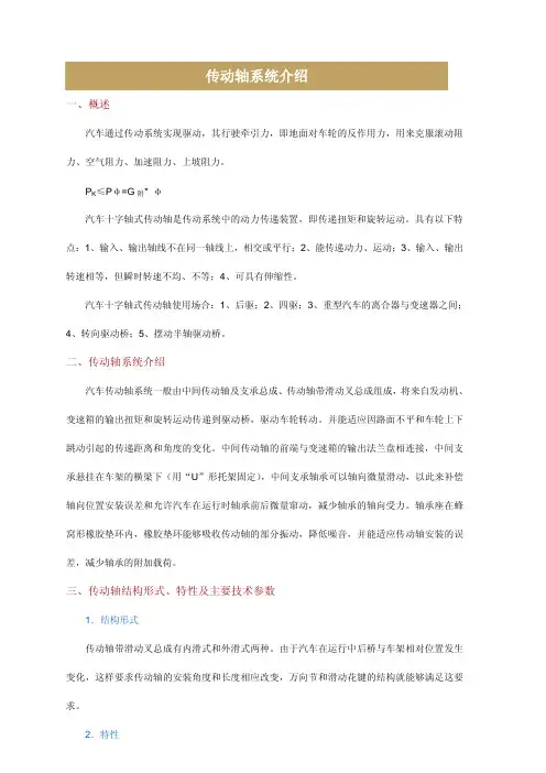
一、概述汽车通过传动系统实现驱动,其行驶牵引力,即地面对车轮的反作用力,用来克服滚动阻力、空气阻力、加速阻力、上坡阻力。
P K≤Pφ=G附* φ汽车十字轴式传动轴是传动系统中的动力传递装置,即传递扭矩和旋转运动。
具有以下特点:1、输入、输出轴线不在同一轴线上,相交或平行;2、能传递动力、运动;3、输入、输出转速相等,但瞬时转速不均、不等;4、可具有伸缩性。
汽车十字轴式传动轴使用场合:1、后驱;2、四驱;3、重型汽车的离合器与变速器之间;4、转向驱动桥;5、摆动半轴驱动桥。
二、传动轴系统介绍汽车传动轴系统一般由中间传动轴及支承总成、传动轴带滑动叉总成组成,将来自发动机、变速箱的输出扭矩和旋转运动传递到驱动桥,驱动车轮转动。
并能适应因路面不平和车轮上下跳动引起的传递距离和角度的变化。
中间传动轴的前端与变速箱的输出法兰盘相连接,中间支承悬挂在车架的横梁下(用“U”形托架固定),中间支承轴承可以轴向微量滑动,以此来补偿轴向位置安装误差和允许汽车在运行时轴承前后微量窜动,减少轴承的轴向受力。
轴承座在蜂窝形橡胶垫环内,橡胶垫环能够吸收传动轴的部分振动,降低噪音,并能适应传动轴安装的误差,减少轴承的附加载荷。
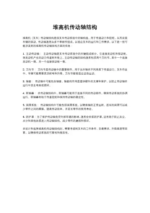
三、传动轴结构形式、特性及主要技术参数1.结构形式传动轴带滑动叉总成有内滑式和外滑式两种。
由于汽车在运行中后桥与车架相对位置发生变化,这样要求传动轴的安装角度和长度相应改变,万向节和滑动花键的结构就能够满足这要求。
2.特性传动轴总成出厂时必须100%进行动平衡校验,并在合适的部位焊接平衡片,以满足传动轴总成的平衡要求。
经验收合格的传动轴在出厂前为保证动平衡,后传动轴的原始装配位置,在后传动轴的轴管与花键滑动叉外表面上喷涂两个相对应的白色油漆箭头。
所有经过拆卸的传动轴在重新恢复时,必须保证装配箭头在一条直线上。
传动轴带滑动叉总成在整车上布置安装时,确保滑动花键接口处向下布置,防止传动轴在使用中雨水泥沙进入配合花键处,影响传动轴的使用寿命。
堆高机传动轴结构
堆高机(叉车)传动轴结构是指叉车传动系统中的轴构造,用于传递动力和扭矩,从而实现车辆的驱动。
传动轴通常由多个零部件组成,以适应叉车的运行和工作需求。
以下是一些可能涉及到的堆高机传动轴结构方面的信息:
1. 主动传动轴:主动传动轴是叉车传动系统中的关键组成部分,它连接发动机和驱动轮,将发动机产生的动力传递到车轮上。
主动传动轴的结构通常包括两个万向节,其中一个连接发动机一侧,另一个连接驱动轮一侧。
2. 万向节:万向节是传动轴中的重要部件,用于允许轴在不同角度下传递动力。
叉车作业中,车辆可能需要灵活转弯和升降,万向节能够适应这些运动。
3. 轴套:传动轴中可能包含轴套,轴套的作用是提供额外的支撑和保护,以防止传动轴在运行中发生弯曲或损坏。
4. 联轴器:在传动轴结构中,联轴器可能用于连接不同的传动部件,确保传动系统的协调运行。
联轴器有助于传递扭矩和保持传动轴的稳定性。
5. 润滑系统:传动轴结构中可能包括润滑系统,以确保轴的正常运转。
适当的润滑可以减少零件之间的摩擦,提高传动效率,并延长零件的使用寿命。
6. 防护罩:为了保护传动轴免受外部环境的影响,通常会安装防护罩。
这有助于防止灰尘、水分和其他杂质进入传动轴结构,减少零件的磨损和损坏。
在设计和选择堆高机传动轴结构时,需要考虑到叉车的工作条件、负载需求、升降高度等因素,以确保传动系统的可靠性和高效性。

传动轴基本知识(图)一、传动轴总成简介传动轴总成图传动轴,英文PROPELLER(DRIVING)SHAFT。
在不同轴心的两轴间甚至在工作过程中相对位置不断变化的两轴间传递动力。
传动轴按其重要部件万向节的不同,可有不同的分类。
如果按万向节在扭转的方向是否有明显的弹性可分为刚性万向节传动轴和挠性万向节传动轴。
前者是靠零件的铰链式联接传递动力的,后者则靠弹性零件传递动力,并具有缓冲减振作用。
刚性万向节又可分为不等速万向节(如十字轴式万向节)、准等速万向节(如双联式万向节、三销轴式万向节)和等速万向节(如球笼式万向节、球叉式万向节)。
等速与不等速,是指从动轴在随着主动轴转动时,两者的转动角速率是否相等而言的,当然,主动轴和从动轴的平均转速是相等的。
主、从动轴的角速度在两轴之间的夹角变动时仍然相等的万向节,称为等速万向节或等角速万向节。
它们主要用于转向驱动桥、断开式驱动桥等的车轮传动装置中,主要用于轿车中的动力传递。
当轿车为后轮驱动时,常采用十字轴式万向节传动轴,对部分高档轿车,也有采用等速球头的;当轿车为前轮驱动时,则常采用等速万向节,等速万向节也是一种传动轴,只是称谓不同而已。
在发动机前置后轮驱动(或全轮驱动)的汽车上,由于汽车在运动过程中悬架变形,驱动轴主减速器输入轴与变速器(或分动箱)输出轴间经常有相对运动,此外,为有效避开某些机构或装置(无法实现直线传递),必须有一种装置来实现动力的正常传递,于是就出现了万向节传动。
万向节传动必须具备以下特点:a、保证所连接两轴的相对位置在预计范围内变动时,能可靠地传递动力;b、保证所连接两轴能均匀运转。
由于万向节夹角而产生的附加载荷、振动和噪声应在允许范围内;c、传动效率要高,使用寿命长,结构简单,制造方便,维修容易。
对汽车而言,由于一个十字轴万向节的输出轴相对于输入轴(有一定的夹角)是不等速旋转的,为此必须采用双万向节(或多万向节)传动,并把同传动轴相连的两个万向节叉布置在同一平面,且使两万向节的夹角相等。

传动轴作用传动轴是通过传递扭矩和转动力矩来实现机械装置或车辆零部件之间的动力传递的一个重要部件。
它由一个或多个连接在一起的轴组成,通常用于将动力从发动机传递到车辆的驱动轮或机械装置的其他部分。
传动轴在汽车、摩托车、农机、建筑机械等各种机械设备中都有广泛应用。
传动轴的主要作用是将发动机的扭矩传递到车辆的驱动轮上,使车辆能够正常行驶。
它通过连接发动机和驱动轮的轮轴与传动总成,将发动机产生的动力传递给车轮,从而推动车辆前进。
传动轴可以根据不同的传动方式分为前驱轴、后驱轴和四驱轴等。
传动轴具有以下几个作用:1. 承载扭矩:传动轴能够承受发动机产生的扭矩,并将其传递给驱动轮或机械装置。
在车辆行驶过程中,传动轴需要承受不同转速和扭矩的变化,因此需要具有足够的强度和刚性来保证其正常运转。
2. 传递动力:传动轴能够将发动机产生的动力传递给驱动轮或机械装置,使其能够正常运转。
通过传动轴传递的动力可以带动车轮旋转,从而使车辆前进。
3. 平衡质量:传动轴在高速旋转时需要平衡质量,以减少振动和噪音。
通过精确加工和平衡检测,可以保证传动轴在高速旋转时的平衡性,提高车辆的运行平稳性和舒适性。
4. 转向支撑:在某些车辆中,传动轴还可以用作转向支撑,增加车辆的稳定性和操控性。
通过连接车轮和底盘,传动轴可以帮助车辆更好地适应道路状况,提高行驶的稳定性和安全性。
总之,传动轴是机械装置或车辆中不可或缺的一个部件,通过传递动力和扭矩来实现动力传递。
它承载着将发动机产生的动力传递给车轮或机械装置的重要任务,对于车辆的正常运行具有至关重要的作用。
同时,传动轴还需要具有足够的强度、刚性和平衡性,以提高车辆的运行平稳性和舒适性。
驱动轴的工作原理
驱动轴(也称为传动轴)是一种用于传递动力的装置,通常用于驱动车辆的车轮或机械设备的运动。
其主要工作原理是通过从发动机或动力装置中获取动力,并将其传递到车辆或设备的驱动轮或驱动机构上。
驱动轴通常由一个或多个万向节组成,它们可以使驱动轴在不同角度和方向上传递动力。
万向节通过连接驱动轴和车轮或传动装置,使得驱动力能够有效地传递,并允许车轮或机械设备在不同的路面或工作条件下正常运动。
当发动机或动力装置运转时,它会产生动力,并通过传动系统将其传递到驱动轴上。
传动系统通常由离合器、变速器和差速器等组成。
离合器用于控制动力的传递和中断,变速器用于调整传动比以调整车轮或设备的速度和扭矩,差速器用于保证车轮的相对速度差,确保在转弯时车轮的正常运动。
一旦动力传递到驱动轴,它就会通过万向节传递到车轮或传动装置。
万向节的设计允许驱动轴在水平和垂直方向上发生弯曲和转动,以适应车轮或设备的运动需求。
总之,驱动轴的工作原理是通过从发动机或动力装置中获取动力,并通过传动系统和万向节将其传递到车轮或传动装置上,以实现车辆或机械设备的驱动和运动。
传动轴的概述
传动轴是一种用于传递动力和转矩的机械元件,通常被用于连接两个旋转部件,例如发动机和车辆的驱动轮。
以下是传动轴的一般概述:
1. 结构形式:传动轴通常由金属材料制成,外形呈圆柱形。
它一般由两端的轴头和中间的轴管组成。
2. 功能:传动轴的主要功能是传递动力和扭矩,使得发动机产生的动力能够传递到车辆的驱动轮上,从而推动车辆运动。
3. 类型:根据不同的传动方式,传动轴可以分为直传动轴、万向传动轴和传动联轴器等不同类型。
4. 安装方式:传动轴通常通过安装在各种机械设备中,如车辆的传动系统、工程机械等。
5. 维护:传动轴作为车辆或机械设备的重要零部件,需要定期进行润滑和检修,以确保其正常工作状态。
总的来说,传动轴作为机械传动系统中的重要组成部分,起着连接和传递动力的关键作用,广泛应用于汽车、工程机械、航空航天等领域。
传动轴、等速万向节检查与紧固一、结构组成发动机前置、前轮驱动的汽车,驱动桥和驱动轮之间通过两根较短的传动轴连接起来,传动系统结构简单,工作可靠。
每根传动轴两端均匀同等速万向节分别连接驱动轮和驱动桥,传动系统结构简单,工作可靠。
传动轴外端是固定式等速万向节,内端是补偿轴距式等速万向节,在等速万向节外定式等速万向节,内端是补偿轴距式等速面有橡胶护套。
二、技术要求①安装车辆配套传动轴、等速万向节及橡胶护套。
②螺栓和螺母紧固力矩符合规定,自锁螺母必须更换新件。
③安装传动轴时,应保持传动轴与轮毂花键的齿面清洁。
三、实训步骤第一步事前准备①车辆进入工位前,清洁场地,准备工具;②将车辆停驻在举升机平台的中央位置;③接紧驻车制动器,并将变速器手柄置于空挡位置;④打开并支撑发动机舱盖;⑤放置各种接紧驻车制动器,并将变速器手柄置于维修护套和护垫;⑥调整并支撑举升机支脚到合适位置。
第二步拆卸等速万向节、传动轴及橡胶护罩①拆卸轮毂固定螺母,拆接紧驻车制动器,并将变速器手柄置于卸前左右车轮。
②拆卸悬架控制球头,将制动盘向外拉,断开驱动桥与传动轴的连接;③将顶拔器的螺杆旋入车轮螺栓孔中,将传动轴顶出,取出传动轴。
④拆卸外等速万向节橡胶护罩上的2个夹箍,将橡胶护罩从万向节的球壳上脱出,并将橡胶护罩沿着传动轴拉离万向节,用橡胶锤敲击万向节球壳,将万向节取下。
⑤将隔套圈、蝶形座圈及橡胶护从万向节的球壳上脱出,并将橡胶护罩沿着传动轴拉离万向罩从传动轴上取下;将等速万向节橡胶护罩的夹箍取下,将橡胶护罩拉出万向节。
⑥取下内等速万向从万向节的球壳上脱出,并将橡胶护罩沿着传动轴拉离万向节的弹簧挡圈,将内等速万向节、蝶形座圈、橡胶护罩从传动轴上取下。
将传动轴、内外等速万向节、蝶形座圈、弹簧挡圈清洗干净。
第三步等速万向节的检查①检查球壳是否存在裂痕、破损等。
如有上述损伤,则应更换万向节总成,球壳与球毂是配合组件。
如存在损伤,应更换万向节总成。
传动轴各轴段的作用传动轴各轴段的作用指的是传动轴各个组成部分所起到的功能和作用。
传动轴是机械传动系统中的重要组成部分,主要用于连接两个不同转速的轴,传递扭矩,使机械设备得以正常运行。
传动轴各轴段的作用可以大致分为以下几个方面:1.连接作用:传动轴通常由多个轴段组成,每个轴段通过轴承或支承座与相应的机械部件连接,起到连接作用,保证机械部件之间的动力传递。
2.支撑作用:传动轴在传递扭矩的同时,还起到支撑作用,支撑着机械部件的重量,保持机械部件的相对位置和稳定性。
3.传递扭矩:传动轴的主要功能是传递扭矩,将动力从一根轴传递到另一根轴上,实现机械设备的正常运转。
4.减震减噪:传动轴在运转过程中,通过各轴段的弹性变形和阻尼作用,吸收和缓冲振动和噪音,提高机械设备的稳定性和舒适性。
接下来,我会提供几个传动轴各轴段作用的示例:示例1:在一个汽车传动系统中,发动机通过离合器和变速器将动力传递到传动轴。
传动轴将动力传递到驱动轮的轮轴上,实现汽车的行驶。
同时,传动轴各轴段在运转过程中会发生弹性变形和阻尼作用,吸收和缓冲振动和噪音,提高汽车的驾驶舒适性。
示例2:在一个风力发电机组中,风力机通过主轴和齿轮箱将动力传递到主传动轴。
主传动轴将动力传递到发电机,使其转动产生电能。
同时,主传动轴各轴段也起到支撑和减震减噪的作用,保持机械部件的相对位置和稳定性,提高风力发电机组的可靠性。
总结:传动轴各轴段的作用指的是传动轴各个组成部分所起到的功能和作用。
这些作用包括连接、支撑、传递扭矩、减震减噪等。
通过了解和掌握传动轴各轴段的作用,可以更好地设计和维护传动系统,提高机械设备的运行效率和稳定性。
传动轴的工作原理
传动轴是一种用于将动力从发动机传输到车辆的车轮上的装置。
它由一系列各向同性的万向节组成,每个万向节由两个可转动的接头和一个连接它们的轴承组成。
传动轴的工作原理是利用万向节的特性来传输扭矩和旋转运动。
当发动机产生的动力传递到传动轴上时,它会通过连接在发动机输出轴的末端的万向节传递。
每个万向节都可以在多个角度和方向上转动,以适应车辆在不同路况下的转向和悬挂运动。
这就使得传动轴能够提供连续的动力传输,无论车轮是在直线行驶、转弯还是过颠簸路面。
当车辆转弯时,一侧车轮需要旋转比另一侧车轮更快或更慢。
这时,传动轴的万向节会根据车辆的悬挂运动和转向角度,以不同的角度来旋转。
它们的转动可以使得车轮获得适当的动力传递,以确保更好的转弯性能和操控稳定性。
传动轴在车辆上的位置通常是沿着车辆的底盘下方或侧面。
它连接着发动机和车轮,起到了一个将动力传输到车轮的关键作用。
同时,传动轴还需要具备良好的耐用性和扭矩传递能力,以适应车辆的高速行驶和负载运输。
因此,在设计和制造传动轴时,需要考虑材料的强度、连接部件的稳定性以及润滑和冷却系统的设计等因素。
总之,传动轴通过万向节的旋转运动,将发动机产生的动力传递给车轮,以驱动车辆行驶。
它的工作原理是依靠万向节的灵活性和转动角度来适应车辆的转向和悬挂运动。
传动轴在车辆
的动力传输系统中扮演着重要的角色,确保了车辆的驱动性能和操控性。
传动轴基本知识一、传动轴总成简介(结合具体总成图)传动轴,英文PROPELLER(DRIVING) SHAFT。
在不同轴心的两轴间甚至在工作过程中相对位置不断变化的两轴间传递动力。
传动轴按其重要部件——万向节的不同,可有不同的分类。
如果按万向节在扭转的方向是否有明显的弹性可分为刚性万向节传动轴和挠性万向节传动轴。
前者是靠零件的铰链式联接传递动力的,后者则靠弹性零件传递动力,并具有缓冲减振作用。
刚性万向节又可分为不等速万向节(如十字轴式万向节)、准等速万向节(如双联式万向节、三销轴式万向节)和等速万向节(如球笼式万向节、球叉式万向节)。
等速与不等速,是指从动轴在随着主动轴转动时,两者的转动角速率是否相等而言的,当然,主动轴和从动轴的平均转速是相等的。
主、从动轴的角速度在两轴之间的夹角变动时仍然相等的万向节,称为等速万向节或等角速万向节。
它们主要用于转向驱动桥、断开式驱动桥等的车轮传动装置中,主要用于轿车中的动力传递。
当轿车为后轮驱动时,常采用十字轴式万向节传动轴,对部分高档轿车,也有采用等速球头的;当轿车为前轮驱动时,则常采用等速万向节——等速万向节也是一种传动轴,只是称谓不同而已。
在发动机前置后轮驱动(或全轮驱动)的汽车上,由于汽车在运动过程中悬架变形,驱动轴主减速器输入轴与变速器(或分动箱)输出轴间经常有相对运动,此外,为有效避开某些机构或装置(无法实现直线传递),必须有一种装置来实现动力的正常传递,于是就出现了万向节传动。
万向节传动必须具备以下特点:a 、保证所连接两轴的相对位置在预计范围内变动时,能可靠地传递动力;b 、保证所连接两轴能均匀运转。
由于万向节夹角而产生的附加载荷、振动和噪声应在允许范围内;c 、传动效率要高,使用寿命长,结构简单,制造方便,维修容易。
对汽车而言,由于一个十字轴万向节的输出轴相对于输入轴(有一定的夹角)是不等速旋转的,为此必须采用双万向节(或多万向节)传动,并把同传动轴相连的两个万向节叉布置在同一平面,且使两万向节的夹角相等。
这一点是十分重要的。
在设计时应尽量减小万向节的夹角。
传动轴总成不平衡是传动系弯曲振动的主要原因。
其引起的振动噪声是明显的。
此外,万向节十字轴的轴向窜动、传动轴滑动花键中的间隙、传动轴总成两端连接处的定心精度、高速回转时传动轴的弹性变形及传动轴上点焊平衡片时的热影响因素等都能改变传动轴总成的不平衡度。
降低传动轴的不平衡度,对于汽车,尤其是高速汽车如(轿车)是极其重要的,否则会引起很多相关故障或异常损坏。
十字轴式刚性万向节传动轴在汽车传动系中用得最广泛,历史也最悠久。
平时所说的传动轴一般指的就是十字轴式刚性万向节传动轴。
十字轴式刚性万向节主要用于传递角度的变化,一般由突缘叉、十字轴带滚针轴承总成、万向节叉或滑动叉、中间连接叉或花键轴叉、滚针轴承的轴向固定件等组成。
突缘叉一般与变速箱、驱动桥或别的传动轴等连接。
突缘叉是一个带法兰的叉形零件,一般采用中碳钢或中碳合金钢的锻造件,也有采用球墨铸铁的砂型铸造件和中碳钢或中碳优质合金钢的精密铸造件。
突缘叉一般带一个平法兰,也有带一个端面梯形齿法兰的。
十字轴带滚针轴承总成一般包括四个滚针轴承、一个十字轴、一个滑脂嘴。
滚针轴承一般由若干个滚针、一个轴承碗、一个多刃口橡胶油封(部分带骨架)组成。
在某些滚针轴承中,还有一个带油槽的圆形垫片,有尼龙的,也有采用铜片或其他材料的,主要用于减小万向节轴向间隙,提高传动轴动平衡品质。
万向节叉是一个叉形零件,一般采用中碳钢或中碳合金钢的锻造件,也有采用中碳钢的精密铸造件。
滚针轴承的轴向固定件一般是孔(或轴)用弹性挡圈(内外卡式),或轴承压板、锁片、螺栓等。
传动轴的另外一个重要的组成部分是滑动花键副,由内、外花键(矩形、渐开线)组成,用于传递长度的变化。
传动轴的万向节摆角和滑动花键副的最大伸缩量,是根据整车布置时进行的传动轴跳动校核而确定的。
传动轴管一般由低碳钢板卷制的电焊钢管制成,对大规格的轴管,也有采用冷拔无缝管的。
轴管的外径和壁厚(或内径)是根据传动轴所传递的最大工作扭矩、最高工作转速等条件确定的。
空心的轴管具有较小的质量并能传递较大的扭矩,并且比相同外径的实心轴具有更高的临界转速的特点。
一般情况下,两万向节中心距不大于 1.5m。
当距离较近时,一般由两个万向节和一个滑动花键副组成,中间无轴管。
当距离较远而使传动轴的长度超过1.5m时,常常分成两根或三根,采用三个或四个万向节,且最后一根带滑动花键副,其余的带中间支承的结构型式。
典型的中间支承一般由一个圆柱球轴承、一个轴承座、两个油封、一个橡胶垫、一个滑脂嘴组成。
中间传动轴由中间支承支架连接到车架横梁上,要求中间传动轴轴心线与中间支承平面垂直。
一般要求传动轴中间支承布置在传动轴系统的一阶临界转速节点上。
在使用过程中,一般需要按时保养。
在万向节、滑动花键副、中间支承等有滑脂嘴的地方,要按有关规定进行定期加注规定的润滑脂。
也有采用免维护的传动轴,在万向节和中间支承的轴承内有预留的润滑脂,不需要定期加注润滑脂。
二、万向节简介万向节是汽车传动轴上的关键部件。
在前置发动机后轮驱动的车辆上,万向节传动轴安装在变速器输出轴与驱动桥主减速器输入轴之间;而前置发动机前轮驱动的车辆省略了传动轴,万向节安装在既负责驱动又负责转向的前桥半轴与车轮之间。
汽车是一个运动的物体。
在后驱动汽车上,发动机、离合器与变速器作为一个整体安装在车架上,而驱动桥通过弹性悬挂与车架连接,两者之间有一个距离,需要进行连接。
汽车运行中路面不平产生跳动,负荷变化或者两个总成安装位置差异,都会使得变速器输出轴与驱动桥主减速器输入轴之间的夹角和距离发生变化,因此要用一个“以变应变”的装置来解决这一个问题,因此就有了万向节。
▲万向节的应用另外在越野车变速器与分动器之间,前驱动的可转向驱动桥与半轴之间,都需要这个万向节做“关节”。
万向节的结构和作用有点象人体四肢上的关节,它允许被连接的零件之间的夹角变化。
但它与肢体关节的活动形式又有所不同,它仅允许夹角在一定范围内变化。
万向节有十字轴式刚性万向节,准等速万向节(双联轴式和三销轴式),等速万向节(球叉式和球笼式),扰性万向节。
目前后驱动汽车上应用最广的一种是十字轴万向节。
单个的万向节不能使输出轴与轴入轴的瞬时角速度相等,容易造成振动,加剧机件的损坏,产生很大的噪音。
因此,后驱动汽车的万向节传动形式都采用双万向节,就是传动轴两端各有一个万向节,其作用是使传动轴两端的夹角相等,保证输出轴与轴入轴的瞬时角速度始终相等。
为了满足动力传递、转向和汽车运行时所产生的上下跳动所造成的角度变化,前驱动汽车的驱动桥,半轴与轮轴之间也常用万向节相连。
由于受轴向尺寸的限制,要求偏角又比较大,普通万向节难以胜任,所以广泛采用各式各样的等速万向节。
在一般前驱动汽车上,每个半轴用两个等速万向节,靠近变速驱动桥的万向节是半轴内侧万向节,靠近车轴的是半轴外侧万向节。
在各种等速万向节中,常见是球笼式万向节,它用六个钢球传力,主动轴与从动轴在任何交角的情况下,钢球都位于两园的交点上,即位于两轴交角的平分面上,从而保证主、从动轴等角速度传动。
Installation conditionsWhile rotating, the universal joint has a sinuslike, fluctuating angular speed depending on the deflection angle. As described in detail in the chapter ,,General fundamental theory", this system-linked fault can be offset for a driving line equipped with two or more joints by choosing special joint arrangements.When dimensioning the drive or the auxlliarv drive, the following rules must be observed in practice:Angle conditions of the universal shaft1. Shaft with two joints"Z-arrangement""W-arrangement"The deflection angles of the joints must be equal: =This rule is also applicable to front view and top view pictures.The joint yokes of the connecting shaft must be in one plane.All three shafts must be in one plane.Note: All these three rules must be observed simultaneously.A joint arrangement in two planes must be avoided if possible. lt is always given when the driving and driven shafts are not in the same plane. If this arrangement is unavoidable and rigid on the installation side, this ,,fault" can be kinematically compensated by a joint misalignment.Front view:Top view:For the resulting deflection angles the following equations are applicable:2. Shaft with three jointsIn cases where greater distances between units have to be bridged, the universal shaft must be supported by an additional, mostly elastic, bearing.In order to keep the remaining irregularity in the drive (joint 3) as small as possible, the sum of all irregulanties of the individualjoints must be equal to or almost equal to zero.(See "Kinematics of Hooke's joints")1. The jointsIn the theory of mechanics the cardan joint or Hooke's joint is defined as a spatial or spherical drive unit with a non-uniform gear ratio or transmission. The transmission behaviour of this joint is described by the equation.In this equation the momentary rotation angle of the driven shaft 2. The motion behaviour of the driving and the driven ends is shown in the following diagram. The asynchronous and / or non-homokinematic running of the shaft 2 is shown in the periodical oscilation of the asynchronous line round the synchronous line (dotted line).A measure for the non-uniformity is the difference of the rotation angles and or the transmission ratio of the angular speeds and .Expressed by an equation, that means:a) rotation angle difference(also called gimbal error)b) Gear ratioThe following diagram shows the gearratio i = / for a full revolution of the universal jointfor ß = 60°.The degree of non-uniformity U is defined by:U = i max. - i min. = tan ß * sin ßwhere:The diagram shows the course of the degree of nonuniformity U and of the angular difference as a function of the deflection angle of the joint from 0 to 45°.From the motion equation it is evident that a homokinematic motion behaviour corresponding to the dotted line under 45° - as shown in the diagram - can only be obtained for the deflection angle ß = 0°. A synchronous or homokinematic running can be achieved by a suitable combination or connection of two or more joints.2. The universal shaftThe rotation angle difference or the gimbal error of a deflected universal joint can be offset under certain installation conditions with a second universal joint. The constructive solutions are the following:1) The deflection angles of both joints must be equal, i.e.Two arrangements are possible:2) The two joints must have a kinematic angular relationship of 90° (/ 2), i.e. the yokes of the connecting shaft are in one plane.For a more intensive study of universal shaft kinematics we refer you to the VDI-recommendation 2722 to the relevant technical literature and especially to the book ,,Kardangelenkgetriebe und ihre Anwendung" (Cardan joint drives and their application) by Florian Duditza, published by VDI.The signs must be entered according to the following sign rule. Here the sign rule is: for the joint positionfor the joint positionThe remaining non-uniformity if any should not be greater than:The minimization of the remaining non-uniformity can also be achieved by the so-called equivalent deflection angle erfolgen.The sign rule is also applicable here.The equivalent deflection angle = 3° is the equivalent deflection angle of a single joint which corresponds with a degree of non-uniformity U = 0,0027.3. Shafts with several jointsIn case of an arrangement with more than three joints proceed as described above.General recommendations for lorry drives:For fast-running drive shafts observe the instructions on the transverse whirling speeds for installation length.(See "Influence of speed and deflection angle")Choose small resulting deflection angles for the main drive range:(See also (n x ß)perm. "Influence of speed and deflection angle")Minimize the angular difference between the joints and the remaining inequaltityIf these recommendations are not observed, one must reckon with vibrations and noises and with a reduced driving comfort as well as with a reduced lifetime of the units.Deflection of joints in two planesIf a "classic shaft arrangement" cannot be realized and the joint deflection cannot be changed, this can be offset by turning the joints. For this shaft arrangement the Installation rule that the resulting deflections of the joints must be equal remains in force, i.e.Plane 1 formed by the driving shaft 1 and the connecting shaft 2 on the one hand and Plane II formed by the connecting shaft 2 and the driven shaft 3 on the other hand form the angle which is offset by turning the joints correspondingly.The torsion angle is determined as follows:The rotation direction results ifom the side view, i.e. joint 1 must be turned to plane 1 by the angle .The shaft must be mounted according to these statements and this before a possible balancing. This position of the joints must be marked with arrows.lnfluence of speed and deflection angleSpeedThe permissible speed of the universal joint shaft is influenced by the following parameters:size of the shaftwidening of the yokes due to centrifugal forcequality of balancingtrue running of the connected flangesdeflection angle during operationlength of the shaftSpeed x deflection angleTheoretical considerations and observations of various applications have shown that certain mass acceleration moments of the centre part of the shaft must not be exceeded if a quiet running of the shaft drives is to be achieved. This mass acceleration moment depends on the speed n, the deflection angle ß and the mass moment of inertia of the centre part of the shaft.The mechanically possible deflection angle for each joint depends on the size of the shaft. Owing to the kinematic conditions of the universal joint described before, the practical deflection angle must be limited in relation to the rotational speed.The following table shows the max. speeds and the max. permissible values for the productof the various shaft sizes for a moment of inertia of the centre part according to a shaft length of approx. 1500 mm.When approaching the critical rotational speed and in the light of the demand of maintenance of balance quality (see Balancing of Propeller shafts ) , it may be necessary to reduce the rotational speed.Joint size n max.[1/min.] (n x ß) perm. [°/min.]2015 2020 2025 2030 2035 2040 2045 2047 2050 2055 2060 2065 6 0006 0006 0006 0005 6005 0004 7004 5004 5004 5004 1003 90027 00026 00024 00022 00021 00020 00019 00019 00019 00018 00017 00017 000Since the quiet running of the universal shaft in practice also largely depends on the installation conditions, the n x ß values shown in the table can only be regarded as a guidance. Slightly higher values are possible. In case of favourable spring and mass conditions the values may be exceeded by up to 50 %.Transverse whirling speedUniversal shafts are flexible elastic units, which must be calculated considering the bending vibrations and the transverse whirling speed.For reasons of safety the max. perm. operating speed must be sufficiently below the transverse whirling speed.The diagram on the end of this page shows the transverse whirling speeds of the varbus shaft sizes depending on the operating lengths and the tube dimensions shown in the catalogue.The diagram values apply to normal installation conditions with a supposed distance of the centre point of the joint shaft from the adjacent bearing equal to 3 x M and a rigid suspension of the connected units.In order to achieve a safe and quiet running behaviour the max. perm. operating speed, i.e. including a possible excess speed, must not exceed 80 % of the transverse whirling speed shown in the diagram.If the permissible speed is exceeded, the length of the universal shaft must be reduced or an intermediate bearing must be provided.The following diagrams only refer to universal shafts of the standard design. For special designs with greater length compensations than normal or with other alterations reducing the flexural strength a special calculation of the critical speed is required. In this case please ask our advice.Transverse whirling speed of cardan shafts dependent on operating lengthDuring operation the universal shaft can be expanded up to this length. The optimumworking length L B of a universal shaft is achieved if the length compensation is extractedby one-third of its length.MaintenanceMaintenance work on cardan shafts used in vehicles and industrial equipment must be done at regular intervals.The scope and the intervals of maintenance work depend on the individual operating conditions of the vehicle or the equipment.Maintenance intervals for cardan shafts in commercial vehiclesDepending on the type of vehicle, the mileage or the service life and the operating conditions two different scopes and intervals of maintenance are required. These are the "minor inspection" and the "major inspection".Use of vehicle Inspection intervalsMinor inspection Major inspectionCommercial vehiclesin long-distance traffic or similarly used vehicles Every 100.000 kmorafter 1 year max.Every 500.000 kmorafter 5 years max.Commercial vehicles used on road and off road and in city traffic and similar Every 50.000 kmorafter 1 year max.Every 300.000 kmorafter 5 years max.Busesin long-distance traffic Every 100.000 kmorafter 1 year max.Every 300.000 kmorafter 3 years max.Busesin city traffic Every 50.000 kmorafter 6 monthsmax.Every 200.000 kmorafter 2 years max.Commercial vehiclesused on sites, communal vehicles, construction machines, cranes, vehicles used in agriculture and forestry, tractors, military vehicles and similar Every 25.000 kmorafter 6 monthsmax.Every 100.000 kmorafter 2 years max.After a change of the vehicle owner or in case of an accident we recommend a "major inspection" of the cardan shaft.Scope of maintenanceMinor inspectionThe "minor inspection" includes checking the cardan shaft installed in a vehicle or in an industrial plant.Check the bolts of the flanges and of the centre bearing bracket for tightness (e.g. undamaged paint coat). If necessary, retighten the bolts with a suitable torque wrench and the torquesprescribed by the manufacturer of the vehicle or equipment.Check whether there are snap rings on all bearing bushes.Check whether balance weights are loose or missing.Check the bottoms of the bearing bushes for change of colour or form due to excessive heat.Visual inspection of the seals of bearing bushes and the length compensation. Defective seals may result in excessive grease loss and breakdown of the cardan shaft.Check whether there are grease nipples on the journal crosses and whether they are in good condition (exception: maintenance-free joints).Check whether the rilsan coat on the sleeve is damaged or shows abrasion.Visual inspection of the centre bearings of drive lines with regard to:- correct position of the rubber cushion in the centre bearing bracket- correct position of the flange shaftIf the distance between the rubber cushion and the outer flinger is too large, the centre bolt may work loose. In this case a check should be made as a part of a major inspection.Carry out a visual inspection for possible damage, e.g.:- damaged paint coat- deformed tubes- eccentricity of the length compensation cover tube- cracks on components and tubeCheck the joints and the length compensation for visible or tangible backlash.If the inspection shows that the cardan shaft is damaged, it must be removed at once and sent to a repair shop that is authorized either by us or by the manufacturer of the vehicle or the equipment.Furthermore, the vehicle or the equipment must be immediately taken out of operation in the case of any extraordinary noise, vibration or otherwise abnormal behaviour. Before recommissioning the cardan shaft it must be checked within the scope of a "minor inspection".Major inspectionEach "major inspection" includes the scope of checking prescribed for a minor inspection. In addition, the cardan shaft must be removed from the vehicle or the equipment for the "major inspection".The following checking or work must be carried out on the cardan shaft:Checking the joint bearings- Check the two flange yokes for tangible backlash or resistance (e.g. hooking) by deflecting them by hand into vertical and horizontal positions (swing them to and fro).- Grease the cross assemblies through the grease nipples and check whether the grease escapes from the seals. If no grease escapes from one or more bearing bushes of a cross assembly or if grease escapes together with water, rust or dirt, the cardan shaft must be sent to an authorized shop for repair.If the joints are in proper condition, regrease them through the grease nipples until the grease escapes from the seals.Checking the length compensation componentsThe involute spline is centred and guided on the spline outer dia. This design allows a maximum backlash of 0,2 mm. The radial backlash need not be checked.- Extend the cardan shaft by approx. 45 mm and place the lugs of the inner yokes at points A and B on a solid support (see illustration).Fix the dial gauge holder at point C next to the weld on the tube and place the dial gauge directly next to the weld of the protective sleeve (cover tube). Lift the cardan shaft at its center of gravity so that the supports at points A and B become free.Read axial backlash on the dial gauge.The max. permissible value is 0,17 mm.- Visual checking of the parts:Extend the cardan shaft completely and check the length compensation for damage to the inside and outside areas of the spline muff and the teeth of the yoke shaft.- Check the seal of the cover tube for damage.If the length compensation is undamaged:- regrease the parts of the length compensation in the sealing area (for grease see Lubrication) and bring the length compensation together to its original length.Attention:Make sure that the marking arrows are opposite one another!Check the centre bearing of drive lines with regard to:- damage to the rubber cushion- firm seat of the ball bearing in the rubber cushionRetighten the central bolt with a torque of 350 Nm.Attention:Centre bearings of older designs with a central nut or holding plate and two bolts (not shown) must not be retightened because the bonding may become damaged and the securing function of the bolting is no longer guaranted. After checking (by retightening) or loosening the bolting a completely new bonding is required.If a major or minor inspection reveals any damage to the shaft, It must be sent to a repair shop that is authorized by either DANA or the manufacturer of the vehicle or equipment.Attention:After each repair the cardan shaft must be rebalanced dynamically.When reinstalling the cardan shaft, please observe the relevant installation instructions (seeInstallation/disassembly).If the cardan shaft is obviously twisted due to over-loading (plastic deformation), it can no longer be used or repaired.LubricationCardan shafts of the series COMPACT 2000 are lubricated ready for operation.The length compensation of the Standard designs is maintenance-free.This does not apply to special designs with an extra large length compensation and a large deflection angle (e.g. cardan shafts between tandem axles). Such a length compensation requires regreasing through a grease nipple in the sealing sleeve of the spline protection until the grease escapes at the scraper seal of the sealing sleeve.The centre bearing is protected by a cover and, filled with grease, is service-free.Cross assemblies must be regreased.The grease reservoir in the cross assemblies can be replenished through a grease nipple. Regreasing must be carried out until the grease escapes out from the seals of the bearings.If it is not possible to grease all four bearings of a cross assembly (i.e. no grease escapes out from the seals), the bearings must be assumed to be damaged.In this case the cardan shaft must be removed and the cross assembly must be replaced in an authorized repair shop. We recommend replacing the other cross assemblies at the same time.For the lubrication of cardan shafts only that grease may be used, which is defined in our standards 4006-005 corresponding to the different application temperatures.Do not use lubricants with MoS2 additives.Clean grease nipples before lubricating.Do not lubricate at high pressure or with pressure surges.Cardan shafts that have been stored for more than 6 months must be regreased before use.The cardan shaft must not be cleaned with pressurized water or a steam jet. In case of doubt the shaft must be regreased until the grease escapes from the seals of the bearings.Recommended regreasing intervals for cardan shafts in commercial vehiclesUnless otherwise prescribed by the manufacturer of the vehicle, we recommend the following regreasing intervals. The data in the table refer to European and similar conditions. Operating conditions other than those shown here may require shorter regreasing intervals.- Regreasing intervals for joints(applicable only in conjunction with approved greases)Use of vehicle Regreasing intervalsCommercial vehiclesin long-distance traffic or similarly used vehicles Everyorafter50.000 km1 year max.Commercial vehicles Every 25.000 km- Greasing intervals for length compensation and centre bearingAs standard the length compensation and the centre bearing are service-free. The lubricating intervals for types designed for periodic relubrication are the same as for joints.。