E+H iTEMP HART TMT162 现场显示型温度变送器简明操作指南
- 格式:pdf
- 大小:1.16 MB
- 文档页数:16
差压变送器正确操作使用步骤变送器如何操作对于工业上大部门的差压变送器,不管是HART协议和布朗协议等差压变送器,安装与调校应注意以下几个问题:1、正确进行误差及回差的计算,正确给出校验结论,正确给出校验结论,正确进行有效数字的处理。
2、设备复位整理:停用三阀组,停电、拆除回路连线及相关设备,压力掌控台启动关闭,打开截止阀及回检阀。
3、校验仪设置功能项,校验仪首先清零,压力管路连接好,同时注意正负极连接,接入标准电阻。
检查回路电流。
4、变送器精度校验:将微调阀放到中心位置,关闭截止阀及回检阀,电动压力检验台输出压力设置,基本误差调校(上行5点,下行5点),适时记录数据。
5、安装时候常常显现松动,变送器与三阀组链接,螺栓应对角缩紧,一般不能一次锁死,三阀组安装时候应当加密封线圈。
6、正确的挂接手操器,依照要求设置变送器内容,零位调整。
7、对于三阀组的操作:首先打开平衡阀,正确开高压阀。
差压变送器在测量过程中常会显现一些故障,因此,在确定程度上影响生产的正常进行,依据相关人员现场多年的实践阅历,总结了一些常见故障判定分析和解决方法。
线路故障:当计算机显示数值不正常时,首先要打开智能差压变送器的接线盒,检查线路是否虚接、短接或者断接,可以通过测电源、量电阻、摇绝缘等方法,进行故障的判定和处理。
采集模块或差压传感器故障:当线路故障排出时,就要看是不是采集模块或差压传感器故障。
使用万用表检查智能差压变送器工作电源是否正常,同时测量智能差压变送器的输出电流值是否在4mA~20mA(假如为输出电压值,测量是否在0~5V)范围内,确认输出值是否正常。
假如无输出值,智能差压变送器损坏,需要更换差压变送器。
假如现场测量值换算与实际阅历值相符,则现场仪表和测点无问题,模块损坏,需更换模块。
当现场测量值换算与计算机显示值相同,说明引压管或智能差压变送器有问题。
引压管故障:1.引压管漏气—由于差压变送器接点、截止阀等附件比较多,导致泄漏点增多,维护工作量增大。
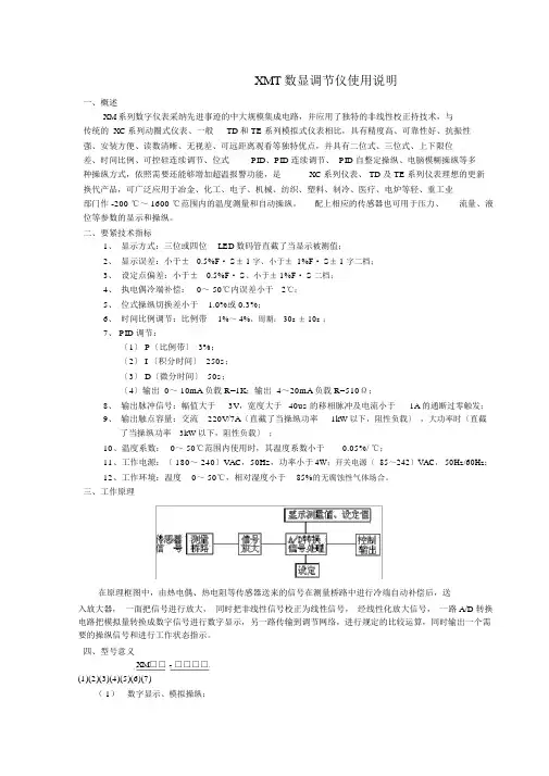
技术资料T I 078R /09/z h /v 1.051002073·高精度·传感器损坏或短路故障信号可预设,符合NA M UR N E 43·E M C 符合N A M UR NE 21,C E ·防爆认证—A T EX —F M —-C SA ·电气隔离·输出模拟·m i n./m ax.测量值指示功能·用户自定义线性化·线性化曲线匹配·用户自定义测量范围设定和扩展设定一体化温度变送器iTEMP HART TMT 182通用型一体化温度变送器,用于热电阻(RT D)、热电偶、电阻和电压信号输入,通过HART 协议组态,安装于传感器内部(Form B )应用场合特点·温度变送器带H AR T 议,用于将各种输入信号转换为4~20m A 输出信号·输入热电阻(R TD )热电偶(T C)电阻(Ω)电压(mV )·通过HA 协议,使用手操器DX R 275或P C (带Com m uw i n I I )进行组态·通用可组态型,适用于各种HA R 协议输入信号·通过PC 进行操作和维护·可使用C o m muw in II 操作软件、二线制技术,4~20mA 模拟输出功能和系统设计测量系统iT EMP HA R T T MT 182一体化温度变送器是二线制变送器,带模拟量输出,输入2-、3-、4-线制热电阻(R TD)信号、热电偶信号和电压信号,通过H AR T 协议,使用手操器D XR 275或P C (Co m mu w in I I)对TM T 182进行组态。
输入测量变量测量范围温度(温度线性传输),电阻和电压变送器测量范围的变化取决于传感器连接模式和输入信号输入类型热电阻(RTD)型号测量范围P t100P t500P t1000符合I EC 751N i100N i500N i1000符合D IN 43760·接线模式:2线,3线,4线连接·2线连接时,通过软件对电缆电阻可进行补偿(0~30Ω)·3线和4线连接时,传感器电缆电阻ma x.20/每芯·传感器电流:≤0.2m AΩ-200~850℃(-328~1562°F)-200~250℃(-328~482°F )-200~250℃(-328~482°F )-60~250℃(-76~482°F )-60~150℃(-76~302°F )-60~150℃(-76~302°F )最小测量范围10K 10K 10K 10K 10K 10K热电偶(TC)电阻(Ω)10~400Ω10~2000Ω0~+1820℃(32~3308°F)0~+2320℃(32~4208°F)0~+2495℃(32~4523°F)-270~+1000℃(-454~1832°F )-210~+1200℃(-346~2192°F )-270~+1372℃(-454~2501°F )-200~+900℃(-328~1652°F)-270~+1300℃(-454~2372°F )-50~+1768℃(-58~3214°F )-50~+1768℃(-58~3214°F )-270~+400℃(-454~752°F )-200~+600℃(-328~1112°F)电阻组态B (P t Rh 30-P t Rh 6)C (W 5Re -W26R e)D (W 3Re -W25R e)E (N i Cr -CuN i )J (F e -C u Ni)K (N i Cr -Ni)L (F e -C u Ni)N (N i Cr S i-N i Si )R (P t Rh 13-P t )S (P t Rh 10-P t )T (C u -C u Ni)U (C u -C u Ni)符合I EC 584P ar t 11122·冷端补偿:内部(Pt100)·冷端精度:±1K电压信号(mV)毫伏(mV )-10~75mV 1.符合ASTM E9882.符合DIN 4371010Ω100Ω500K 500K 500K 50K 50K 50K 50K 50K 500K 500K 50K 50K5mV输出输出信号模拟量420mA 204m A3.8mA 20.5m A(T C )3.6m A 21.0m A ma x.(V -11.5V )/0.022A ()1060s U=2kV AC (/)5234s (I =3.8m A)~,~·低于测量下限输出降至·高于测量上限输出升至·传感器损坏;传感器短路热电偶除外≤或≥电流输出温度线性化,电阻线性化,电压线性化第级数字过滤器:~输入输出≤3.m A ≤mA上电过程中电源a 报警信号负载线性化传输特性过滤器电气隔离输入电流电流限制延迟开关/电气连接电源变送器端子接线图电源U =11.5~35V ,极性保护b 电流波动允许波动U ≤3V (当U ≥13V ,f =1k H z 时)S S b m ax 4~20mA 2-线3-线4-线11.5~35V 11.5~30V Ex性能特性响应时间1s参考操作条件标定温度+23℃(73.4°F )±5K最大测量误差测量精度1热电阻(R TD )类型环境温度影响(温度漂移)长期稳定性负载影响P t100N i100P t500N i500P t1000Ni 1000,,,0.2K 或0.08%0.5K 或0.20%0.3K 或0.12%热电偶(T C)K ,J ,T ,E ,L ,U N ,C ,D S ,B ,Rt yp.0.5K 或0.08%t yp.1.0K 或0.08%t yp.2.0K 或0.08%电阻信号(Ω)±0.1Ω或0.08%±1.5Ω或0.12%10~400Ω10~2000Ω电压信号(mV )±20μV 或0.08%-10~75m V范围测量测量精度11)%是相对于可调的测量范围(取大值)冷端影响电压影响≤±0.01%/V 偏离24V 满量程值的百分比·热电阻(R T D):T =±(15pp m /K *最大测量范围+50pp m /K *预设测量范围)*△θ·热电阻(P t 100):T =±(15pp m /K *(测量范围终值+200)+50ppm /K*预设测量范围)*△θ·热电偶(T C ):T =±(50pp m /K *最大测量范围+50pp m /K *预设测量范围)*△θ△θ=环境温度对参考温度的偏离(+23℃(73.4°F)+5K )·±0.02%/100Ω相对于满量程值·≤0.1K /年或≤0.05%/年参考条件下的数值,%相对于设定量程,最大值有效Pt 100D IN IE C 751C l.B(热电偶T C 内部冷端)d d d 安装指南·安装角度:无限制·安装区域:接线腔符合D IN 43729F or m B ;TAF 10外壳安装指南-40~+85℃(-40185F )防爆区-40~+100℃212符合EN 60654-1,C l ass C 允许IP 00,I P 66安装4g /2150H z ,符合I EC 60068-2-6抗干扰和辐射符合EN 61326-1(IE C 1326)和N AM UR N E 21~°,(-40~°F)~环境条件环境温度范围贮存温度气候等级冷凝防护等级抗震性电磁兼容性(EMC)≈40g变送器外壳:PC ,P ot ti n g :P UR电缆max.1.75m m2机械结构尺寸变送器尺寸,mm(inche s)重量材质端子温度变送器无显示元件,可通过R e a dW i n 2000、C om m uwi n I I 或Fie l d Ca r e Pc 软件显示测量值无操作元件,通过Re ad W in2000P C 操作软件对温度变送器进行远程组态HA RT 手操器D X R 275或P C 带Co m m ub ox F X A 191和操作软件(R e a dW i n 2000,Co mm uw i n I I 或Fi e ldC a r e)PC 接口R S 232的Co m m ub ox F X A 191传感器类型和连接方式、工程单位(℃/°F)、测量范围、内部/外部冷端、二线制测量时的线阻补偿、故障模式、输出信号(4~20/204m A )()T A G +(8+16)mi n./m a x.组态接口可组态参数~、数字过滤器阻尼、偏置、描述字符、输出模拟、用户自定义线性化,测量值指示功能。

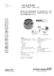
XMT数显调节仪使用说明一、概述XM系列数字仪表采纳先进事迹的中大规模集成电路,并应用了独特的非线性校正持技术,与传统的 XC系列动圈式仪表、一般TD和 TE 系列模拟式仪表相比,具有精度高、可靠性好、抗振性强、安装方便、读数清晰、无视差、可远距离观看等独特优点,并具有二位式、三位式、上下限位差、时间比例、可控硅连续调节、位式PID、PID 连续调节、 PID 自整定操纵、电脑模糊操纵等多种操纵方式,依照需要还能够增加超温报警功能,是XC 系列仪表、 TD 及 TE 系列仪表理想的更新换代产品,可广泛应用于冶金、化工、电子、机械、纺织、塑料、制冷、医疗、电炉等轻、重工业部门作 -200 ℃~ 1600 ℃范围内的温度测量和自动操纵。
配上相应的传感器也可用于压力、流量、液位等参数的显示和操纵。
二、要紧技术指标1、显示方式:三位或四位LED数码管直截了当显示被测值;2、显示误差:小于±0.5%F· S± 1 字、小于± 1%F· S± 1 字二档;3、设定点偏差:小于±0.5%F· S、小于± 1%F· S 二档;4、执电偶冷端补偿:0~ 50℃内误差小于2℃;5、位式操纵切换差小于 1.0%或 0.3%;6、时间比例调节:比例带1%~ 4%,周期: 30s ± 10s ;7、 PID 调节:〔1〕 P〔比例带〕 3%;〔2〕 I 〔积分时间〕 250s;〔3〕 D〔微分时间〕 50s;〔4〕输出 0~ 10mA负载 R=1K;输出 4~20mA负载 R=510Ω;8、输出脉冲信号:幅值大于3V,宽度大于40us 的移相脉冲及电流小于1A 的通断过零触发;9、输出触点容量:交流220V/7A〔直截了当操纵功率1kW以下,阻性负载〕,大功率时〔直截了当操纵功率3kW以下,阻性负载〕;10、温度系数:0~ 50℃范围内使用时,其温度系数小于0.05%/ ℃;11、工作电源:〔 180~ 240〕VAC,50Hz,功率小于4W;开关电源〔 85~242〕VAC, 50Hz/60Hz;12、工作环境:温度0~ 50℃,相对湿度小于85%的无腐蚀性气体场合。
Services Pressure Flow TemperatureLiquid AnalysisRegistrationSystemComponentsLevel SolutionsRTDOmnigrad S TR66-200...+600500barIP68Endress+Hauser4...20mA HARTPROFIBUS PA(FF)Ex d Ex ia ExnAOmnigrad S TR66B RIA261RIA261RIA2614...20mARIA2612.5V RIA261RIAA RN221N()Omnigrad S TR66RN221N 24VDC 30mA 20...250V DC/AC 50/60HzOmnigrad S TR66Omnigrad S TR661TPR100 2TPR3003456(6mm)Ex ia Ex nA(6mm)NTUA=U+TIL=U+T+N+41mmOmnigrad S TR66Pt100Pt100Pt100 -200...600IEC60751()4MPaOmnigrad S TR66()D1=35mm Q1=25mm Q2=18mm D1=30mmQ1=20mm Q2=14mmA T=50BT=400L 1.4401v4g/2...150HzIEC 60068-2-6Omnigrad S TR66RTD IEC607511)=()|t|IEC607510.4m/s10100V DC100MRTD RTDEndress+HauseriTEMPITS90Endress+Hauser RTD-80...+600:mm()6mmOmnigrad S TR661)800Endress+Hauser(/)%Omnigrad S TR66iTEMP 4...20mATMT180TMT181(PC )TMT182(HART)PCiTEMPPCEndress+HauserReadWin InternetHART iTempDXR275/375(FieldCare ReadWin PC AMSPDMTMT84(PROFIBUS PA)Callendar-Van Dusen -PROFIBUS PA TMT84PCFieldCare Simatic PDMAMSDIPFFTMT85PCEndress+Hauser Control NICallendar-Van Dusen-TMT85(FF)TMDIN43729form B(EN50014/18EN50281-1-1) XPmm Omnigrad S TR66Omnigrad S TR66mmOmnigrad S TR66IL U+T+L+41mmN T U123ID A Omnigrad S TR66D1Q1Df Q21200mmOmnigrad S TR661.5...5.5 kg()(ASME B16.5, ANSI B1.20.1)mm1) RF SORaised Face Slip()Endress + Hauser11Omnigrad S TR66(Pt100) TPR100 TPR300 316L/1.4401 MgO12Endress + HauserOmnigrad S TR66TMT18x()4...20 mA( () )( ( ( () ) ) )()TMT84/85()2 RTD /1 RTDEndress + Hauser13Omnigrad S TR66A-B C-D( B ) ) ( C D ) (A14Endress + HauserOmnigrad S TR66NCEndress + Hauser15Omnigrad S TR66CEOmnigrad S TR66 Endress+Hauser ExEC CE (ATEX CSA FM ) Endress+HauserIEC 60529 (IPIEC 61010-1 )IEC 60751IEC 43772EN 50014/18, DIN 47229EN 61326-1 (EMC)(PED)1 2.1(97/23/EC) CE EN 10204 3.1 Endress+Hauser DIN 43772 ( ) TZC138 TZC125IEC 60751 Endress+HauserTZC135 TZC133/13416Endress + HauserOmnigrad S TR66Omnigrad S TR66A C E H K L M ATEX II 1 GD EEx ia IIC ATEX II 2 GD EEx d IIC ATEX II 3 GD EEx nA II TIIS Ex ia IIC T4 TIIS Ex ia IIC T6 ATEX II 1/2 GD EEx d IICA B C YTA21H, TA30H, TA30H,, IP66 , IP66/IP68 , IP66/IP67;A B C D E F Y1 2 1 2 1 21/2" NPT 1/2" NPT 3/4" NPT 3/4" NPT M20 1.5 M20 1.5NB C E F G J YFitting69 mm; 316; N 1/2" NPT M 109 mm; 316; N 1/2" NPT M 148 mm; 316; N 1/2" NPT M 69 mm; A105; N 1/2" NPT M 109 mm; A105; N 1/2" NPT M 148 mm; A105; N 1/2" NPT M ... mm;B C D Y316Ti 316 316LT1 2 6 9D1DfQ1Q270 mm; 30 mm; 7 mm; 20 mm; 14 mm 75 mm; 35 mm; 7 mm; 24 mm; 14 mm 100 mm; 35 mm; 8 mm; 25 mm; 18 mm ... mm;UX Y... mm ... mm;TR66-()Endress + Hauser17Omnigrad S TR66Omnigrad S TR66 ( )CA CB CC CD CE CF CG CH CJ CK CL CM CQ CS CT CV JA JB JC JD JE JF YY 11 22 441" ANSI 150 RF SO ; A105 1" ANSI 150 RF SO ; B16.5; JPI; 316 1" ANSI 300 RF SO ; A105 1" ANSI 300 RF SO ; B16.5; JPI; 316 1" ANSI 600 RF SO ; A105 1" ANSI 600 RF SO ; 316 1 1/2" ANSI 150 RF SO ; A105 1 1/2" ANSI 150 RF SO ; B16.5; JPI; 316 1 1/2" ANSI 300 RF SO ; A105 1 1/2" ANSI 300 RF SO ; B16.5; JPI; 316 1 1/2" ANSI 600 RF SO ; A105 1 1/2" ANSI 600 RF SO ; 316 2" ANSI 300 RF SO ; A105 2" ANSI 600 RF SO ; A105 2" ANSI 600 RF SO ; 316 2" ANSI 300 RF SO ; 316 10K25A RF JIS B 2220 ; 316 10K40A RF JIS B 2220 ; 316 10K50A RF JIS B 2220 ; 316 20K25A RF JIS B 2220 ; 316 20K40A RF JIS B 2220 ; 316 20K50A RF JIS B 2220 ; 316 3/4" NPT-M 1" NPT-M R 3/4", JIS B 0203; 316B C D F G H 2 3 4 5TMT84 PA TMT85 FF TMT181 (PCP); TMT182 (HART); TMT180-A21 fix; 0.2 K, TMT180-A22 fix; 0.1 K, TMT180-A11 PCP; 0.2 K, TMT180-A12 PCP; 0.1 K,, , , ,-200/650 -50/250 -200/650 -50/250RTDA B C F G Y 2 3 6 7;;; -200/600 ; -200/600 ; -200/600 ; -200/600 ; -200/600 ; A: -200/600 ; A: -200/600 ; A: -200/600 ; 1/3B; 0/250 ; 1/3B; 0/250 , , , ,1x Pt100(WW); 2x Pt100(WW); 1x Pt100(WW); 2x Pt100(WW); 1x Pt100(WW); 1x Pt100(TF); 1x Pt100(TF); 1x Pt100(TF); 1x Pt100(TF);; -50/400 ; A; -50/250 ; -50/400 ; A; -50/250 ; -50/400 ; 1/3B; 0/150 ; -50/400 ; 1/3B; 0/150Y 0TR66-18Endress + HauserOmnigrad S TR66FA 006T/09/en TI 088R/09/en TI 070R/09/en TI 078R/09/en TI 138R/24/ae TI 134R/24/ae TI 079R/09/en TI 268T/02/ae TI 290T/02/ae XA 003T/02/z1 TI 236T/02/en XA 015T/02/z1 TI 091T/02/eniTEMP Pt TMT180 iTEMP PCP TMT181 iTEMP HART TMT182 iTEMP PA TMT84 iTEMP FF TMT85 iTEMP PA TMT184 Omniset TPR100 RTD Omniset TPR300 RTD (TPR100) (TPR300) Omnigrad TA50 TA55TA60TA70TA75Endress + Hauser19Omnigrad S TR664008 86 2580458 (021)24039600 24039700 (021)24039607 200241 E-mail: info@ 99 16 (010)59572888 (010)59572700 100176 E-mail: ehbj@B-D-22 (028) 66002128 (028) 66070084 (028) 66070085 610041 E-mail: ehcd@68 B 1606 (0531)86110426 (0531)86110584 250011 E-mail: ehjn@418 V207 (0551)2863897 (0551)2863887 230001 E-mail: ehhf@67 A2 1103 (025) 84805000 (025) 84805302 210009 E-mail: ehnj@19 2 2619 (0731) 8855487 8859768 (0731) 8856537 410006 E-mail: ehcs@628 A 2308 (027) 87854540 87854601 (027) 87665231 430070 E-mail: ehwh@1110 2101 (0755)33225328 33225325 (0755)33235326 (0755)33225327 518054 E-mail: ehsz@96-6 1208 (024) 86131178 (024) 86131799 110031 E-mail: ehsy@88 B 802 (029) 87651280 (029) 87651278 710068 E-mail: ehxa@368 812 (0451)85977500 85977600 (0451)85977100 150090 E-mail: ehhr@2 22 H (0991) 5587692 5587695 (0991) 5589109 830000 E-mail: ehxj@88 C1 8 (0871)3634650 (0871)3638622 650011 E-mail: konde@3355 13 606 (0431) 87025888 87027755 (0431) 87023666 130012 E-mail: ehcc@TI284T/28/zh/08.09。
Products Solutions Services操作手册iTEMP TMT82温度变送器,带双输入通道HART ®通信协议BA01028T/28/ZH/25.22-00715964312022-04-04自下列版本起生效01.02(版本号)iTEMP TMT82目录Endress+Hauser 3目录1文档信息 (4)1.1文档功能 (4)1.2《安全指南》(XA) (4)1.3信息图标 (4)1.4工具图标 (5)1.5文档资料 (6)1.6注册商标 (6)2基本安全指南 (7)2.1人员要求 (7)2.2指定用途 (7)2.3工作场所安全 (7)2.4操作安全 (7)2.5产品安全 (8)2.6IT 安全 (8)3到货验收和产品标识 (9)3.1到货验收 (9)3.2产品标识 (9)3.3制造商名称和地址 (10)3.4供货清单 (11)3.5证书和认证 (11)3.6储存和运输 (11)4安装 (12)4.1安装要求 (12)4.2安装仪表 (12)4.3安装后检查 (18)5电气连接 (19)5.1接线要求 (19)5.2快速接线指南 (20)5.3连接传感器电缆 (22)5.4连接变送器 (23)5.5特殊接线指南 (23)5.6保证防护等级 (24)5.7连接后检查 (24)6操作方式 (26)6.1操作方式概览 (26)6.2操作菜单的结构和功能 (27)6.3测量值显示与操作单元 (28)6.4通过调试软件访问操作菜单 (30)7变送器的HART ®集成 (33)7.1HART 设备参数和测量值 (33)7.2HART 设备参数和测量值 (33)7.3支持的HART ®命令 (34)8仪表调试..........................368.1安装后检查..........................368.2打开变送器..........................368.3激活设置............................369维护..............................3610维修..............................3710.1概述...............................3710.2备件...............................3710.3处置...............................3711附件..............................3711.1设备专用附件........................3711.2通信专用附件........................3811.3服务专用附件........................3811.4系统产品............................3912诊断和故障排除...................4012.1故障排除............................4012.2诊断事件............................4112.3返厂...............................4512.4软件历史和兼容性概述.................4513技术参数..........................4613.1输入...............................4613.2输出...............................4713.3电源...............................4813.4性能参数............................4913.5环境条件............................5613.6机械结构............................5713.7证书和认证..........................6113.8文档资料............................6214操作菜单和菜单参数说明...........6314.1“Setup”菜单.........................7014.2“Diagnostics”菜单.....................8814.3“Expert ”菜单........................97索引. (115)文档信息iTEMP TMT824Endress+Hauser1 文档信息1.1 文档功能《操作手册》包含设备生命周期内各个阶段所需的所有信息:从产品标识、到货验收和储存,至安装、电气连接、操作和调试,以及故障排除、维护和废弃。

Products Solutions ServicesSafety Instructions Temperature transmitteriTEMP TMT142, TMT1621ExdIICT6...T4 X, DIP A21 TA 110°C0ExiaIICT6...T4 X Document: XA01453T Safety instructions for electrical apparatus for explosion-hazardous areas → 3XA01453T/09/EN/01.1671344268Temperature transmitter XA01453TTemperature transmitteriTEMP TMT142, TMT162Table of contentsAssociated documentation (4)Supplementary Documentation (4)EAC certificate of conformity according to TR CU 012/2011 (4)Manufacturer address (4)Safety instructions: Ex d (5)Safety instructions: Ex ia (7)Temperature tables (9)Electrical connection data (9)Endress+Hauser3XA01453T Temperature transmitter 4Endress+HauserAssociated documentationThis document is an integral part of the following Operating Instructions:•TMT142:BA00191R/09/•TMT162 HART®:Operating Instructions: BA00132R/09/Brief Operating Instructions: KA00250R/09/•TMT162 FOUNDATION Fieldbus™:Operating Instructions: BA00224R/09/Brief Operating Instructions: KA00189R/09/•TMT162 PROFIBUS® PA:Operating Instructions: BA00275R/09/Brief Operating Instructions: KA00276R/09/The Operating Instructions which correspond to the device type apply.Supplementary DocumentationExplosion-protection brochure:CP00021Z/11EAC certificate of conformity according to TR CU 012/2011The temperature transmitters meet the fundamental health and safety requirements for the design and construction of devices and protective systems intended for use in potentially explosive atmospheres in accordance with TR CU 012/2011.Certification body: НАНИО "ЦСВЭ"Certificate number: TC RU C-DE.ГБ05.B.00919Affixing the certificate number certifies conformity with the following standards:GOST 30852.0-2002 (IEC 60079-0:1998)GOST 30852.1-2002 (IEC 60079-1:1998)GOST 30852.10-2002 (IEC 60079-11:1999)GOST IEC 61241-1-1-2011Manufacturer addressEndress+Hauser Wetzer GmbH + Co KG Obere Wank 1D-87484 Nesselwang Germany Phone: +49 (0)8361 308 0Temperature transmitter XA01453T Endress+Hauser 5Safety instructions: Ex dXA01453T Temperature transmitter6Endress+HauserSafety instructions: Installation•Comply with the installation and safety instructions in the Operating Instructions.•Install the device according to the manufacturer's instructions and any other valid standards and regulations (e.g. ГОСТ 30852.13-2002(МЭК 60079-14:1996)).•The housing of field transmitter must be connected to the potential matching line.•Only the approved wire entries as specified in paragraph 10.4 of ГОСТ 30852.13-2002 (МЭК 60079-14:1996), paragraph 16 of ГОСТ 52350.0-2002 (МЭК 60079-0:1998), paragraph 13 of ГОСТ30852.1-2002 (IEC 60079-1:1998) must be used.•For connection through a conduit entry approved for this purpose the associated sealing facility shall be mounted directly to the housing.•Seal unused entry glands with approved sealing plugs that correspond to the type of protection.•For operating the transmitter housing at an ambient temperature under –20 °C, appropriate cables and cable entries permitted for this application must be used.Temperature transmitter XA01453T Endress+Hauser 7•For ambient temperatures higher than +70 °C, use suitable heat-resisting cables or wires, cable entries and sealing facilities for Ta +5 K above surrounding.•During operation, the cover must be screwed all the way in and the cover's safety catch must be fastened.•The remote or integral mounted temperature sensor must comply with the requirements according to ГОСТ 30852.1-2002 (IEC 60079-1:1998).Safety instructions: Special conditions Explosive atmosphere ‣Do not open the electrical connection of the power supply circuit in an explosive atmosphere.•Use for remote temperature sensors only approved sensors certified for category 2G marked not less than II2G Ex d IIC T6…T4 Gb for use in Zone 1.•Use for integral temperature sensors only approved sensors certified for category 1 marked not less than 1ExdIICT6…T4 X for use in Zone 1.•The temperature class specified for the certified temperature sensor shall be taken into account.•The temperature transmitter must be installed so, that even in the event of rare incidents, an ignition source due to impact or friction between the enclosure and iron/steel is excluded.Safety instructions: Ex iaXA01453T Temperature transmitter 8Endress+HauserSafety instructions: Installation•Comply with the installation and safety instructions in the Operating Instructions.•Install the device according to the manufacturer's instructions and any other valid standards and regulations (e.g. ГОСТ 30852.13-2002(МЭК 60079-14:1996)).•The type of protection changes as follows when the devices are connected to certified intrinsically safe circuits of Category ib: Ex ib IIC. When connecting an intrinsically safe ib circuit, do not operate the sensor at Zone 0.•When connecting two independent sensors make sure that the potential equalization cables are at the same potential.Temperature transmitter XA01453T Endress+Hauser 9Safety instructions: Zone 0•Only operate devices in potentially explosive vapour/air mixtures under atmospheric conditions:–20 °C ≤ Ta ≤ +60 °C •If no potentially explosive mixtures are present, or if additional protective measures have been taken, according to ГОСТ31438.1-2011 (EN 1127-1:2007),, the transmitters may be operated under other atmospheric conditions in accordance with the manufacturer's specifications.•Associated apparatus with galvanic isolation between the intrinsically safe and non-intrinsically safe circuits are preferred.Safety instructions: Special conditions The temperature transmitter must be installed so, that even in the event of rare incidents, an ignition source due to impact or friction between the enclosure and iron/steel is excluded.Temperature tablesElectrical connection dataFor 1ExdIICT6...T4 XXA01453T Temperature transmitter For 0ExiaIICT6...T4 X10Endress+Hauser。

一体化温度变送器、概述一体化温度变送器可直接测量各种生产过程中的-50℃~+500℃范围内液体、蒸汽、气体介质以及固体表面温度,同时输出标准4~20mADC或1~5VDC模拟信号。
广泛用于石油、化工、冶金、电站、轻工等部门,与调节器、记录仪表、计算机等配套使用,组成各种测量控制系统,用户可根据使用要求选择适当的产品。
2、主要技术指标⑴供电电源:额定电压DC24V,供电电压范围DC(10~30)V(带显示表头的:15~30VDC);纹波小于1.0%。
⑵输出信号:模拟信号:4~20mADC/1~5VDC(与被测温度成线性关系)⑶工作环境:-10~+80℃(带3 1/2LCD显示时,环境温度为-10~+60℃)⑷相对湿度:≤80%⑸测量温度范围:-50℃~+500℃⑹测量精度等级:1.0,0.5⑺常温绝缘电阻:环境温度为15~35°C,相对湿度45~75%,试验电压为直流500V,输出接线端子与外套管之间的绝缘电阻不小于50MΩ。
3、结构、外型、安装尺寸3.1 结构材料壳体:专用电子壳体—铸铝赫斯曼接头—1Cr18Ni9Ti不锈钢防水接线盒—铸铝外保护管:1Cr18Ni9Ti不锈钢安装螺纹、安装法兰:1Cr18Ni9Ti不锈钢3.2结构及外型尺寸59~图44、开箱、保管及成套性4.1 开箱开箱时应注意(1)首先检查包装箱是否完整无缺,箱体应按“↑”标志放置。
(2)开箱时避免用力过大的敲打,以免损伤仪表或附件。
4.2 成套性变送器出厂时应包括一体化温度变送器1台指示表(显示表)1台(按合同要求)产品说明书1份产品合格证1份质量跟踪卡1份4.3 保管:产品应储存环境温度为-40~80℃,相对湿度不大于80%的干燥通风的室内,室内空气中无腐蚀性气体。
5、安装5.1安装前的检查(1)一体化温度变送器的测量范围是否适应现场的实际测量。
(2)安装方式、安装螺纹尺寸是否符合现场的实际情况。
5.2 安装(1)一体化温度变送器的安装方向应为任意方向,必须使一体化温度变送器测温端充分接触测量介质,保证外保护管插入深度。
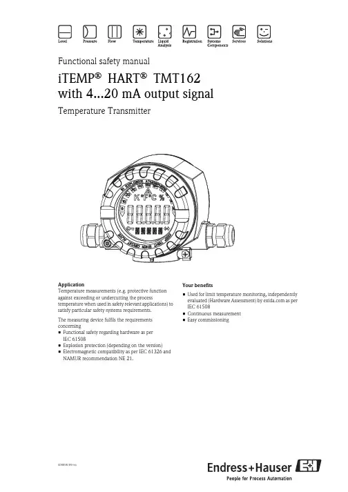
Functional safety manualiTEMP® HART® TMT162 with 4...20 mA output signalTemperature TransmitterApplicationTemperature measurements (e.g. protective function against exceeding or undercutting the process temperature when used in safety relevant applications) to satisfy particular safety systems requirements.The measuring device fulfils the requirements concerning•Functional safety regarding hardware as perIEC61508•Explosion protection (depending on the version)•Electromagnetic compatibility as per IEC61326 and NAMUR recommendation NE 21.Your benefits•Used for limit temperature monitoring, independently evaluated (Hardware Assessment) by as per IEC 61508•Continuous measurement•Easy commissioningSD005R/09/eniTEMP® HART® TMT162 Table of contentsManufacturer Declaration . . . . . . . . . . . . . . . . . . . . . .3Introduction. . . . . . . . . . . . . . . . . . . . . . . . . . . . . . . . .4Abbreviations, standards and terms . . . . . . . . . . . . . . . . . . . . . . . . 4Determining the Safety Integrity Level (SIL) . . . . . . . . . . . . . . . . . 4Safety function with TMT162 . . . . . . . . . . . . . . . . . . .5Safety function for limit temperature monitoring . . . . . . . . . . . . . . 5Safety function data . . . . . . . . . . . . . . . . . . . . . . . . . . . . . . . . . . . 5Unit version . . . . . . . . . . . . . . . . . . . . . . . . . . . . . . . . . . . . . . . . . 5Supplementary device documentation TMT162 . . . . . . . . . . . . . . 5Commissioning and iterative tests. . . . . . . . . . . . . . . .6Using the TMT162 forcontinuousmeasurements . . . . . . . . . . . . . . . . . . . . . . . . . . . . . . . . . . . . . . . 6Settings . . . . . . . . . . . . . . . . . . . . . . . . . . . . . . . . . . . .6Settings . . . . . . . . . . . . . . . . . . . . . . . . . . . . . . . . . . . . . . . . . . . . 6Safety-related parameters . . . . . . . . . . . . . . . . . . . . . .6Specific safety-related parameters for TMT162 . . . . . . . . . . . . . . . 6PFDAVG dependent on selected maintenance interval . . . . . . . . . 7Repair . . . . . . . . . . . . . . . . . . . . . . . . . . . . . . . . . . . . .7Repair . . . . . . . . . . . . . . . . . . . . . . . . . . . . . . . . . . . . . . . . . . . . . 7 management summary. . . . . . . . . . . . . . . .8Appendix: Declaration of Hazardous Material and De-Contamination. . . . . . . . . . . . . . . . . . . . . . . . . . . . . .112Endress+HauseriTEMP® HART® TMT162General managerEndress+Hauser3iTEMP® HART® TMT1624Endress+HauserIntroductionAbbreviations, standards and termsAbbreviationsExplanation to the abbreviations used can be found in the SIL-Brochure (SI002Z/11).Relevant standardsTermsDetermining the Safety Integrity Level (SIL)The achievable Safety Integrity Level is determined by the following safety-related parameters:•Average Probability of Failure on Demand (PFD AVG )•Hardware Fault Tolerance (HFT) and •Safe Failure Fraction (SFF).The specific safety-related parameters for the TMT162, as a part of a safety function, are listed in the "Safety-related parameters" chapter.The following table displays the dependence of the "Safety Integrity Level" (SIL) on the "Average Probability of Failure on Demand" (PFD AVG ). Here, the "Low demand mode" has been observed, i.e. the requirement rate for the safety-related system is maximum once a year.Sensor, logic unit and actuator together form a safety-related system, which performs a safety function. The "Average Probability of Failure on Demand" (PFD AVG ) is usually divided up into the sensor, logic unit and actuator sub-systems as per Figure 1.Fig. 1: usual division of the "Average Probability of Failure on Demand" (PFD AVG ) into the sub-systems!Note!This documentation considers the TMT162 as a sensor sub-system.Standard ExplanationIEC 61508,Part 1 – 7Functional safety of electrical/electronic/programmable electronic safety-related systems (Target group: Manufacturers and Suppliers of Devices)IEC 61511Part 1 – 3 (FDIS)Functional safety – Safety Instrumented Systems for the process industry sector (Target group: Safety Instrumented Systems Designers, Integrators and Users)Term ExplanationDangerous failureFailure with the potential to put the safety-related system in a dangerous or non-functional condition.Safety-related systemA safety-related system performs the safety functions that are required to achieve or maintain a safe condition e.g. in a plant. Example: temperature measuring device – logic unit (e.g. limit signal generator) – valve form a safety-related system.Safety functionDefined function, which is performed by a safety-related system with the aim of achieving or maintaining a safe condition for the plant, considering a specified dangerous incident. Example: limit temperature monitoringSafety Integrity Level (SIL)PFD AVG (Low demand mode)4≥ 10–5...< 10–43≥ 10–4...< 10–32≥ 10–3...< 10–21≥ 10–2...< 10–1iTEMP® HART® TMT162Endress+Hauser 5Safety Integrity Level TMT162 (Type B)The following table displays the achievable "Safety Integrity Level" (SIL) of the entire safety-related system for type B systems depending on the "Safe Failure Fraction" (SFF) and the "Hardware Fault Tolerance" (HFT). Type B systems are, for example, sensors with complex components such as ASICs (→ see also IEC 61508, Part 2).Safety function with TMT162Safety function for limit temperature monitoringFig. 2: safety function (e.g. for limit temperature monitoring) with TMT162 as sub-systemThe TMT162 transmitter generates an analogue signal (4...20 mA) proportional to the temperature. The analogue signal is fed to a downstream logic unit, such as a PLC or limit signal generator, and there it is monitored to determine whether it exceeds a maximum value. In order to monitor for faults, the logic unit must be able to detect both HI-alarms ≥ 21.6 mA and LO-alarms ≤ 3.6 mA.Safety function data"Caution!The data for the safety functions are listed in the "Safety-related parameters" chapter.!Note!MTTR is set at eight hours.Safety-related systems without a self-locking function must be monitored or set to an otherwise safe state after carrying out the safety function within MTTR.Unit versionHardware assessment valid from Hardware Revision: 1.01.00 and Software Revision: 1.02.01Supplementary device documentation TMT162Depending on the version, the following documentation must be available for the temperature transmitter iTEMP ® HART ® 162:Safe Failure Fraction (SFF)Hardware Fault Tolerance (HFT)012< 60%not permitted SIL 1SIL 260 ...< 90 %SIL 1SIL 2SIL 390 ...< 99 %SIL 2SIL 3–≥ 99 %SIL 3––Explosion protection/Certificates Operating instructions Other Ex-Documentation noneBA132R noneATEX II 1 G EEx ia IIC T4/T5/T6BA132R Safety instructions XA033R ATEX II 2 G EEx d IIC T6BA132RSafety instructions XA031RiTEMP® HART® TMT1626Endress+Hauser"Caution!•The installation and setting instructions, and the technical limit values must be observed in accordance with the Operating Instructions (BA132R).•For devices which are used in explosion-hazardous, the supplementary documentation (XA) resp. Control Drawings must also be used in accordance with the table.iTEMP ® HART ® TMT162 supplementary documentation For further information, see Technical Information TI086R.Commissioning and iterative testsUsing the TMT162 for continuous measurementsThe operability of the safety installation must be tested at appropriate time intervals. It is the responsibility of the user to select the type of check and the intervals in the specified time frame. The test must be completed in such a way that the fault free function of the safety installation combined with all components can be vaildated.SettingsSettingsIt is possible to do various settings (hardware and software set-up) on the TMT162. For further information see the BA132R operating instructions.Safety-related parametersSpecific safety-related parameters for TMT162The table displays the specific safety-related parameters for the TMT162.ATEX EEx d, EEx iaBA132RSafety instructions XA031R Safety instructions XA033R Safety instructions XA034R ATEX II 3 G EEx nA IIC T4/T5/T6BA132R Safety instructions XA035R ATEX II 1/2 DBA132RSafety instructions XA032RExplosion protection/Certificates Operating instructions ControlDrawings FM ControlDrawings CSA noneBA132R none none FM IS I/1+2/A-D CSA IS I/1+2/A-DBA132R 14 12 00 11114 12 00 112FM XP, DIP, NI I,II,III/1+2/A-G CSA XP, DIP, NI I,II,III/1+2/A-G BA132R 14 12 00 11314 12 00 114FM XP, DIP, IS, NI I,II,III/1+2/A-G CSA XP, DIP, IS, NI I,II,III/1+2/A-G BA132R 14 12 00 11114 12 00 11314 12 00 11214 12 00 114FM XP, DIP, IS, NI I,II,III/1+2/A-G CSA XP, DIP, IS, NI I,II,III/1+2/A-GBA132R14 12 00 11114 12 00 11314 12 00 11214 12 00 114Explosion protection/Certificates Operating instructions Other Ex-Documentation TMT162with sensor TC 1TMT162with sensor RTD/4-wire 1HFT 00SFF> 92 %> 91 %iTEMP® HART® TMT162Endress+Hauser 7PFD AVG dependent onselected maintenance interval The following diagram presents the dependence of the PFD AVG on the maintenance interval. The PFD AVG increases as the maintenance interval increases.Fig. 4: "Average Probability of Failure on Demand" (PFD AVG ) dependent on the selected maintenance intervalRepairRepair!Note!Together with the failed, SIL-marked E+H device, having been operated in a functional safety application, the form "Declaration of Hazardous Material and De-Contamination" containing the appropriate information ":Used as SIL device in a Safety Instrumented System" has to be returned.The "Declaration of Hazardous Material and De-Contamination" can be found in the Appendix at the end of this Functional Safety Manual.PFD AVG 1,97 x 10–39,64 x 10–4TI 2annualannual1) direct connection, vibration protected 2)Complete function testTMT162with sensor TC 1TMT162with sensor RTD/4-wire1iTEMP® HART® TMT1628Endress+Hauser management summary© e x i d a .c o m G m b H e +h 02-11-05 r 006 v 1 r 1.4, J u l y 30, 2003 S t e p h a n A s c h e n b r e n n e r P a g e 2 o f 22M a n a g e m e n t s u m m a r yT h i s r e p o r t s u m m a r i z e s t h e r e s u l t s o f t h e h a r d w a r e a s s e s s m e n t c a r r i e d o u t o n t h e t e m p e r a t u r e f i e l d t r a n s m i t t e r i T E M P ® H A R T ® T M T162 w i t h s o f t w a r e v e r s i o n V 1.02.01.T h e h a r d w a r e a s s e s s m e n t c o n s i s t s o f a F a i l u r e M o d e s , E f f e c t s a n d D i a g n o s t i c s A n a l y s i s (F M E D A ). A F M E D A i s o n e o f t h e s t e p s t a k e n t o a c h i e v e f u n c t i o n a l s a f e t y a s s e s s m e n t o f a d e v i c e p e r I E C 61508. F r o m t h e F M E D A , f a i l u r e r a t e s a r e d e t e r m i n e d a n d c o n s e q u e n t l y t h e S a f e F a i l u r e F r a c t i o n (S F F ) i s c a l c u l a t e d f o r t h e d e v i c e . F o r f u l l a s s e s s m e n t p u r p o s e s a l l r e q u i r e m e n t s o f I E C 61508 m u s t b e c o n s i d e r e d .T h e f a i l u r e r a t e s u s e d i n t h i s a n a l y s i s a r e b a s e d o n t h e S i e m e n s s t a n d a r d S N 29500.A c c o r d i n g t o t a b l e 2 o f I E C 61508-1 t h e a v e r a g e P F D f o r s y s t e m s o p e r a t i n g i n l o w d e m a n d m o d e h a s t o b e t 10-3 t o < 10-2 f o r S I L 2 s a f e t y f u n c t i o n s a n d t 10-2 t o < 10-1 f o r S I L 1 s a f e t y f u n c t i o n s . A g e n e r a l l y a c c e p t e d d i s t r i b u t i o n o f P F D A V G v a l u e s o f a S I F o v e r t h e s e n s o r p a r t , l o g i c s o l v e r p a r t , a n d f i n a l e l e m e n t p a r t a s s u m e s t h a t 35% o f t h e t o t a l S I F P F D A V G v a l u e i s c a u s e d b y t h e s e n s o r p a r t . T h e t o t a l P F D A V G v a l u e o f t h e S I F s h o u l d b e s m a l l e r t h a n 1,00E -01 f o r a S I L 1 a p p l i c a t i o n a n d s m a l l e r t h a n 1,00E -02 f o r a S I L 2 a p p l i c a t i o n . T h e r e f o r e t h e m a x i m u m a l l o w a b l e P F D A V G v a l u e f o r t h e s e n s o r p a r t w o u l d t h e n b e 3,50E -02 f o r a S I L 1 a p p l i c a t i o n a n d 3,50E -03 f o r a S I L 2 a p p l i c a t i o n .T h e t e m p e r a t u r e f i e l d t r a n s m i t t e r i T E M P ® H A R T ® T M T 162 i s c o n s i d e r e d t o b e a T y p e B 1 c o m p o n e n t w i t h a h a r d w a r e f a u l t t o l e r a n c e o f 0.F o r T y p e B c o m p o n e n t s t h e S F F h a s t o b e b e t w e e n 60% a n d 90% f o r S I L 1 (s u b -) s y s t e m s a n d b e t w e e n 90% a n d 99% f o r S I L 2 (s u b -) s y s t e m s w i t h a h a r d w a r e f a u l t t o l e r a n c e o f 0 a c c o r d i n g t o t a b l e 2 o f I E C 61508-2.A s s u m i n g t h a t a c o n n e c t e d l o g i c s o l v e r c a n d e t e c t b o t h o v e r -r a n g e (f a i l h i g h ) a n d u n d e r -r a n g e (f a i l l o w ), h i g h a n d l o w f a i l u r e s c a n b e c l a s s i f i e d a s s a f e d e t e c t e d f a i l u r e s o r d a n g e r o u s d e t e c t e d f a i l u r e s d e p e n d i n g o n w h e t h e r t h e t e m p e r a t u r e t r a n s m i t t e r i s u s e d i n a n a p p l i c a t i o n f o r “l o w l e v e l m o n i t o r i n g ”, “h i g h l e v e l m o n i t o r i n g ” o r “r a n g e m o n i t o r i n g ”. F o r t h e s e a p p l i c a t i o n s t h e f o l l o w i n g t a b l e s s h o w h o w t h e a b o v e s t a t e d r e q u i r e m e n t s a r e f u l f i l l e d .T a b l e 1: S u m m a r y f o r t h e t r a n s m i t t e r T M T 162 – P F D A V G v a l u e sT [P r o o f ] = 1 y e a rT [P r o o f ] = 5 y e a r sT [P r o o f ] = 10 y e a r sP F D A V G = 8,75E -04 P F D A V G = 4,36E -03 P F D A V G = 8,96E -03T a b l e 2: S u m m a r y f o r t h e t r a n s m i t t e r T M T 162 – F a i l u r e r a t e sF a i l u r e C a t e g o r i e sλs dλs uλd dλd uS F FD C S 2 D C Dλl o w = λs d λh i g h = λd d66 F I T270 F I T120 F I T200 F I T> 69%20% 38%λl o w = λd d λh i g h = λs d108 F I T270 F I T79 F I T200 F I T> 69%29% 28%λl o w = λs d λh i g h = λs d166 F I T270 F I T21 F I T200 F I T> 69%38% 10%T y p e B c o m p o n e n t :“C o m p l e x ” c o m p o n e n t (u s i n g m i c r o c o n t r o l l e r s o r p r o g r a m m a b l e l o g i c ); f o r d e t a i l s s e e 7.4.3.1.3 o f I E C 61508-2. 2 D C m e a n s t h e d i a g n o s t i c c o v e r a g e (s a f e o r d a n g e r o u s ) o f t h e s a f e t y l o g i c s o l v e r f o r t h e t e m p e r a t u r e t r a n s m i t t e r .T h e d o c u m e n t w a s p r e p a r e d u s i n g b e s t e f f o r t . T h e a u t h o r s m a k e n o w a r r a n t y o f a n y k i n d a n d s h a l l n o t b e l i a b l e i n a n y e v e n t f o r i n c i d e n t a l o r c o n s e q u e n t i a l d a m a g e s i n c o n n e c t i o n w i t h t h e a p p l i c a t i o n o f t h e d o c u m e n t . © A l l r i g h t s r e s e r v e d .F M E D A i n c l u d i n g S F F d e t e r m i n a t i o n a n d P F D A VG c a l c u l a t i o nP r o j e c t : T e m p e r a t u r e f i e l d t r a n s m i t t e r i T E M P ® H A R T ® T M T 162C u s t o m e r :E n d r e s s +H a u s e r W e t z e r G m b H + C o . K GN e s s e l w a n g G e r m a n yC o n t r a c t N o .: E +H 02/11-05 R e p o r t N o .: E +H 02/11-05 R 006 V e r s i o n V 1, R e v i s i o n R 1.4, J u l y 2003 S t e p h a n A s c h e n b r e n n e riTEMP® HART® TMT162Endress+Hauser9© e x i d a .c o m G m b H e +h 02-11-05 r 006 v 1 r 1.4, J u l y 30, 2003 S t e p h a n A s c h e n b r e n n e r P a g e 3 o f 22 A u s e r o f t h e t e m p e r a t u r e f i e l d t r a n s m i t t e r i T E M P ® H A R T ® T M T 162 c a n u t i l i z e t h e s e f a i l u r e r a t e s i n a p r o b a b i l i s t i c m o d e l o f a s a f e t y i n s t r u m e n t e d f u n c t i o n (S I F ) t o d e t e r m i n e s u i t a b i l i t y i n p a r t f o r s a f e t y i n s t r u m e n t e d s y s t e m (S I S ) u s a g e i n a p a r t i c u l a r s a f e t y i n t e g r i t y l e v e l (S I L ). A f u l l t a b l e o f f a i l u r e r a t e s f o r d i f f e r e n t o p e r a t i n g c o n d i t i o n s i s p r e s e n t e d i n s e c t i o n 5.1 a l o n g w i t h a l l a s s u m p t i o n s . A c o m p l e t e t e m p e r a t u r e s e n s o r a s s e m b l y c o n s i s t i n g o f T M T 162 a n d a c l o s e l y c o u p l e d t h e r m o c o u p l e o r c u s h i o n e d 4-w i r e R T D s u p p l i e d w i t h T M T 162 c a n b e m o d e l e d b y c o n s i d e r i n g a s e r i e s s u b s y s t e m w h e r e a f a i l u r e o c c u r s i f t h e r e i s a f a i l u r e i n e i t h e r c o m p o n e n t . F o r s u c h a s y s t e m , f a i l u r e r a t e s a r e a d d e d . S e c t i o n 5.2 g i v e s t y p i c a l f a i l u r e r a t e s a n d f a i l u r e d i s t r i b u t i o n s f o r t h e r m o c o u p l e s a n d R T D s w h i c h w e r e t h e b a s i s f o r t h e f o l l o w i n g t a b l e s . A s s u m i n g t h a t T M T 162 i s p r o g r a m m e d t o d r i v e i t ’s o u t p u t h i g h o n d e t e c t e d f a i l u r e s o f t h e t h e r m o c o u p l e o r R T D (λl o w = λd d , λh i g h = λs d ), t h e f a i l u r e r a t e c o n t r i b u t i o n o r t h e P F D A V G v a l u e f o r t h e t h e r m o c o u p l e o r R T D i n a l o w s t r e s s e n v i r o n m e n t i s a s f o l l o w s :T a b l e 3: S u m m a r y f o r t h e s e n s o r a s s e m b l y T M T 162 / t h e r m o c o u p l e i n l o w s t r e s s e n v i r o n m e n tT [P r o o f ] = 1 y e a r T [P r o o f ] = 5 y e a r sT [P r o o f ] = 10 y e a r sS F FP F D A V G = 1,97E -03 P F D A V G = 9,86E -03P F D A V G = 1,97E -02 > 92% λs d = 4,86E -06 1/h = 4858 F I T λs u = 2,70E -07 1/h = 270 F I T λd d = 7,85E -08 1/h = 79 F I T λd u = 4,50E -07 1/h = 450 F I TT a b l e 4: S u m m a r y f o r t h e s e n s o r a s s e m b l y T M T 162 / 4-w i r e R T D i n l o w s t r e s s e n v i r o n m e n tT [P r o o f ] = 1 y e a r T [P r o o f ] = 5 y e a r sT [P r o o f ] = 10 y e a r sS F FP F D A V G = 9,64E -04 P F D A V G = 4,82E -03P F D A V G = 9,64E -03 > 91% λs d = 2,09E -06 1/h = 2088 F I T λs u = 2,70E -07 1/h = 270 F I T λd d = 7,85E -08 1/h = 79 F I T λd u = 2,20E -07 1/h = 220 F I TT a b l e 5: S u m m a r y f o r t h e s e n s o r a s s e m b l y T M T 162 / 2/3-w i r e R T D i n l o w s t r e s s e n v i r o n m e n tT [P r o o f ] = 1 y e a r T [P r o o f ] = 5 y e a r sT [P r o o f ] = 10 y e a r sS F FP F D A V G = 2,63E -03 P F D A V G = 1,31E -02P F D A V G = 2,63E -02 > 70% λs d = 1,71E -06 1/h = 1708 F I T λs u = 2,70E -07 1/h = 270 F I T λd d = 7,85E -08 1/h = 79 F I T λd u = 6,00E -07 1/h = 600 F I TiTEMP® HART® TMT162 10Endress+HauseriTEMP® HART® TMT162Endress+Hauser11iTEMP® HART® TMT162International Head QuarterEndress+HauserGmbH+Co. KGInstruments InternationalColmarer Str. 679576 Weil am RheinDeutschlandTel. +49 76 21 9 75 02Fax +49 76 21 9 75 34 5***************.comSD005R/09/en/12.05FM+SGML 6.0 ProMoDo。

压力温度变送器操作规程温度变送器同压力变送器的操作使用基本相同,压力变送器下有二阀组(三阀组),温度变送器则无,下面主要讲述压力变送器的操作规程。
1检查和准备1.1压力变送器安装的环境温度和压力必须符合规定。
1.2通电前,仔细检查电源的正负极性,不要接错,供电电压应在正常范围内。
1.3拆卸压力变送器时,必须断开24VDC电源,并做好接线标记。
关闭该压力变送器的取压阀,然后断开现场仪表电源线,同时做好接线标记和接线头的绝缘保护。
1.4注意电缆接头的密封塞和电缆是否出现松动和老化现象,以便防尘防水。
1.5防爆铭牌清晰完好。
1.6严禁在危险场所开盖。
1.7每月检查一次检查引压管线有无渗漏。
1.8每半年进行一次仪表零位检查和量程检查。
1.9每年检定一次。
1.10每月检查一次两侧表盖是否拧紧,密封圈是否老化。
1.11每月检查一次防爆接头密封性检查。
1.12日常检查应校核压力变送器测量值是否准确,否则及时上报生产科进行处理。
2操作内容和步骤2.1(压变的启用)操作2.1.1检查各引压管及仪表电源线都连接好,三阀组处于切断状态。
2.1.2打开三阀组的平衡阀。
2.1.3开启压力变送器三阀组连接正、负压室的针形阀门。
2.1.4快速开启放空阀,排出管内的积液然后关闭。
2.1.5然后关闭平衡阀,变送器投入正常工作。
2.2停用压力变送器操作2.2.1打开三阀组的平衡阀,使变送器的正、负压室压力平衡。
2.2.2关闭正、负压室的截断阀,这时仪表表头指示应回零。
2.2.3打开放空阀,放空三阀组。
3操作后检查3.1检查开启三阀组后各连接管路是否漏气,表头指针指示是否正常。
3.2检查停用三阀组后仪表表头指示是否回零。
4风险提示及削减措施4.1风险提示:引压管线出现渗漏,引起爆炸。
削减措施:1)加强对各连接部件的检漏;2)定期对压力变送器的维护保养。
5维护保养为了保证变送器的测量精度和使用寿命,应定期地对变送器运行状态进行检查。
(1)外观检查目视检查变送器各部件有没有损伤、腐蚀现象。
HART手持式操作通信器使用说明书目录一、使用说明 (2)二、连接 (2)三、主菜单 (3)四、在线调试状态 (4)1、过程变量 (4)2、附加信息 (5)3、量程修改 (5)4、环路测试 (6)5、线性化 (7)6、压力微调 (9)7、其它 (9)五、装箱清单项 (10)一、按键操作说明:光标移动键:光标在各项菜单中的上、下、左、右的移动。
字符选择键:只局限在修改数据过程中对数字信息的选取。
确认键:用于各菜单的选取和数字信息的选取。
修改键:用于对仪表的数据信息的修改。
背光键:用于背光的打开与关闭。
电源键:用于电源的打开与关闭。
退出键:用于各项菜单的退出。
功能键:用于扩展功能(待用)。
特定功能键:向上光标移动键:用于在监测“过程变量”中的退出。
二、连接所需仪器:一台智能变送器;一台HART手持式操作通信器(简称:手操器);一台12~45VDC电源;一个大于或等于250欧的负载电阻;一台精密毫安表或毫伏表;一台标准精密压力计(压力计精度至少比变送器高3倍)。
连接如下图所示:变送器线性化安装图注:为保证可靠通信,请将负载电阻串联在电源的正极。
三、主菜单按下面板中“电源开/关”按键,单点通讯将出现HART手操器主菜单。
如右轮询通讯图1所示:“单点通讯”在“零号地址码”可使用,若仪表的地址码不为“零号”,则应用“轮询通讯”方式通讯。
菜单中的“▋”为需要选择的图1 主菜单选项。
按“确认”按键进入在线调试状态(图2)四、在线调试状态在线调试状态是一个设置的窗口,主要包括七部分组成,如下图2中所示。
可根据用户的需要进行不同的读取与设置。
各个选项的具体操作说明在下面各章节中详细说明。
1、过程变量 如右图3所示。
本选项可以查看仪表的“PV ”(压力)、“I ”(电流)、“PER ”(百分数值)、“T ”(环境温度)、“LRV ”(零位)、“URV ”( 量程)、“LSL ”(最大测量范围低限)、“USL ”(最大测量范围高限)。
4...20 mA 模拟量电流输出,提供多种外壳型号,应用广泛应用•通用型温度变送器,将不同类型的输入信号转换为4...20mA 模拟量电流输出信号•iTEMP TMT71具有高可靠性、高长期稳定性和高测量精度,配备高级诊断功能,尤其满足关键工艺段的测量要求•最高安全性和最高可靠性,最低使用风险•通用输入信号:连接热电阻(RTD)、热电偶(TC)、电阻(Ω)、电压(mV)输入•安装在B 类(平面)接线盒中测量•可选:在Ex d 隔爆场合中安装在现场型外壳中使用•可选:设备采用DIN 导轨安装优势•通过多项国际认证,可以在防爆危险区中安全测量•配备传感器和设备监测功能,测量可靠•诊断信息符合NAMUR NE107标准•可选TID10插拔式测量值显示单元•自带Bluetooth®蓝牙接口,支持无线远程测量值显示,可通过Endress+Hauser SmartBlue(app)进行设备组态设置•可选用直推式接线端子技术,无需借助其他工具即可快速完成接线Products Solutions Services技术资料iTEMP TMT71温度变送器TI01393T/28/ZH/04.22-00715869582022-03-18iTEMP TMT712Endress+Hauser功能与系统设计测量原理工业温度测量中各类输入信号的电子记录和转换。
测量系统1应用实例1分体式安装方式:热电阻(RTD)或热电偶(TC)传感器和变送器分开安装,例如模块化变送器安装在现场型外壳中或使用DIN 导轨盘装型变送器2一体式安装方式:模块化变送器内安装有一支绕线式热电阻(RTD)或热电偶(TC)Endress+Hauser 生产多种类型的工业温度计,包括热电阻传感器或热电偶。
与温度变送器配套使用,组成完整的测量系统,提供完整的工业温度测量解决方案。
两线制温度变送器带一路测量输入信号和一路模拟量输出信号,温度变送器可转换热电阻、热电偶、电阻和电压信号,将不同输入信号转换成4...20 mA 电流信号。
温度变送器使用说明书一、用途本产品广泛用于石油、化工、冶金、电力、轻工、建材等行业,实现对流体温度的测量,可适用于工业测量的各种场合及介质,是工业自动化领域理想的压力测量仪表。
二、特点1、选用具有国际先进水平的传感器,配合高精度的元器件,经严格的工艺过程装配而成,因此在使用温度范围内非线性小,长期稳定性好。
2、可靠的机械保护IP65和防爆保护dⅡBT4/T6,适用于各种恶劣环境。
3、可用于测量粘稠、结晶及腐蚀性介质。
4、4~20mADC标准电流信号输出,二线制工作。
可定制HART/485等数字输出。
5、体积小,重量轻,安装、调试、使用方便。
三、技术指标被测介质:与316不锈钢兼容的液体、气体、蒸汽,特殊介质需定制测量范围:-50~450℃输出:4~20mADC二线制准确度:0.2%FS,0.5%FS温度影响系数:±0.15%FS/10℃稳定性:优于0.2%FS/年电源电压:DC 6.5~36VDC 机械保护:IP65防爆等级:dⅡBT4/T6 温度极限:使用温度-40~80℃存贮温度:-20~+50℃过载极限:额定量程的1.5倍~3倍相对湿度:≤95%RH 负载电阻:≤750Ω四、物理性能隔离膜片:304不锈钢接触介质连接件:SUS304不锈钢过程连接方式:1/2NPT外螺纹,M20×1.5外螺纹(可自定义接口)电气连接:电缆孔为Φ8五、工作原理过程压力通过压力传感器将压力信号转换成电信号,经差分放大器、输出放大器放大后,再经V/A转换器转换为与输入压力成线性对应关系的4~20mA标准电流输出信号。
六、接线方式小巧型接线端子示意图 2088型端子示意图七、按键说明用户参数菜单(进入方式:按,输入密码:3001)(1)参数组:用于变送器用户选项调节注1:INP:输入类型选择。
根据选用传感器类型调节参数,可选传感器见表2。
注2:BSL:变送低限值,即输出4mA对应的显示值。
注3:BSH:变送高限值,即输出20mA对应的显示值。
简明操作指南iTEMP HART TMT 182®KA142R/09/zh/08.0871120768模块化温度变送器TMT182 iTEMP® HART TMT182模块化温度变送器目录1 安全指南 (3)2 功能 (4)3 外形尺寸 (4)4 安装 (4)5 接线示意图 (6)6 操作 (8)7 附件 (10)8 补充文档 (11)TMT1821 安全指南TMT182是一款通用型预设置模块化温度变送器,可连接热电阻(RTD)、热电偶(TC)、电阻及电压信号。
制造商对由于误操作而引起的仪表损坏不承担任何责任。
在防爆区中测量的仪表,单独成册的防爆手册(Ex)是仪表操作手册的组成部分。
必须完全遵守其中规定的安装条件和电气连接参数要求。
专业人员必须事先仔细阅读仪表操作手册,方可进行仪表的安装和接线操作。
TMT182温度变送器采用模块化结构设计,不可维修。
已损坏的仪表,必须遵照当地的废弃物处置规定进行相应的报废处理。
TMT182模块化温度变送器由电源供电,供电电路必须符合IEC 61010-1标准规定的能量限制电路:“SELV或2类电路”要求。
TMT182 2 功能在工业温度测量中,基于电子监控和传输控制,将多种输入信号转换成模拟输出信号。
可以通过HART®手操器(DXR275/375),或安装有操作软件(Commuwin II、FieldCare或ReadWin®2000)的PC机对TMT182进行仪表设置。
3 外形尺寸[mm(inch)]4 安装环境温度:-40...+85°C(-40...+185°F);防爆区中测量时,请参考相关防爆手册(Ex)安装位置:安装在TAF10现场外壳内;安装在符合DIN 43729标准的B类表头内安装角度:无限制TMT182TMT182 5 接线示意图TMT182HART通信的接线通过HART手操器DXR275/375通信或利用安装有Endress+Hauser操作软件的PC机通过Commubox FXA191连接通信(详情请参考“操作”部分)。