固定翼单座轻型飞机图纸
- 格式:doc
- 大小:2.44 MB
- 文档页数:25

固定翼飞机设计计算公式集锦经过几年来的努力学习和收集,现在把掌握到的一些计算公式和大家分享。
一部分是前人的经验公式,经过验算后,保守取值的,还有不少余量。
还有一部分是取保守系数,从复杂的数学公式演变而来,通俗表达了,供文化程度不高的朋友们参考。
如果哪位用此理论指导自制飞机,建议请专业人士求证,本人对此造成的任何后果概不负责。
如有错误的地方,欢迎批评指正。
一、发动机与螺旋桨1.飞机最大起飞重量W(公斤)=发动机最大功率(千瓦)×10. 82.螺旋桨转速R(转/分钟)×螺旋桨直径D(米)=32503.螺旋桨转速R(转/分钟)=170÷(D直径×3.14÷60)4.螺旋桨直径D(米)=170÷转速(转/分钟)÷0.0523注:*桨尖线速度=50%音速发动机与螺旋桨匹配参考值:- -可修编.发动机功率(hp)353025201510(待续)抄来的图纸,自己翻译的,和大家共享-FURIA轻型固定翼飞机构造图(中文版)(1)(抄来的图纸哦!- -可修编.- -可修编.- -可修编.- -可修编.- -可修编.抄来的图纸,自己翻译的,和大家共享-FURIA轻型固定翼飞机构造图(中文版)(1)(- -可修编.- -可修编.- -可修编.- -可修编.- -可修编.- -可修编.发2次都- -可修编.发航空技术版块去了,不知道为什么?重发一下!- -可修编.- -可修编.- -可修编.- -可修编.- -可修编.抄来的图纸,自己翻译的,和大家共享-FURIA轻型固定翼飞机构造图(中文版)(2)(- -可修编.- -可修编.- -可修编.- -可修编.- -可修编.- -可修编.抄来的图纸,自己翻译的,和大家共享-FURIA轻型固定翼飞机构造图(中文版)(3)(- -可修编.- -可修编.- -可修编.- -可修编.- -可修编.- -可修编.抄来的图纸,自己翻译的,和大家共享-FURIA轻型固定翼飞机构造图(中文版)(4)(- -可修编.- -可修编.- -可修编.- -可修编.- -可修编.- -可修编.。


用Auto CAD绘制模型飞机加工图(上)橙子喜欢自己设计制作模型飞机的模友,大都离不开一些电脑辅助设计软件,如AutoCAD、Profili、Design foil、CATIA、AAA(Advanced.Aircraft.Analysis)等。
它们可用于绘制平面图、构建三维模型、提供翼型数据以及进行模型飞机的总体设计分析等。
掌握好其中的AutoCAD、Profili和AAA三种软件,即可完成大多数模型飞机的设计制作。
如今数控激光雕刻机应用广泛,详细的加工图纸会给模型飞机的制作带来很大方便,并能保证制作精度和美观程度。
不过很多模友仅能根据设计自己画出模型飞机三面图(图1),而不知如何将其转化为详细的加工制作图。
下面笔者以一架双尾撑布局的固定翼模型飞机(采用倒V形尾翼、上单翼、发动机推进式设计)为例,介绍自己依据三面图用AutoCAD绘制加工图的心得和体会。
图1 模型飞机的三面图首先要保证三面图准确、清晰;然后根据经验和简单计算,确定每个部位的材料和尺寸;之后便可开始绘制加工图了,主要分为机翼、机身和尾翼三个部分。
机翼图2 选择翼型对于常规的固定翼模型飞机,机翼通常由翼肋、主梁、后梁(又称后墙)和前缘定位条构成。
翼肋图纸可通过一些专门的翼型软件得到,如用Profili软件产生一个翼型文件,再导入AutoCAD中。
具体步骤如下:打开Profili软件,如图2所示,点击键1,从出现的对话框中选择所需翼型(这里选NACA4412);点击键2,在弹出的对话框中输入图3所示的各选项,按OK键确定;待翼型图纸弹出后(图4),点键3“保存为DXF格式”(默认格式)到自建的文件夹内,即可得到所需翼型的CAD文件。
该翼型的弦长为100mm,可按实际需要缩放。
图3 设置翼型参数图4 保存为DXF格式用AutoCAD打开已有模型飞机的三面图,把翼型图纸复制上去(图1),准备绘制翼肋加工图。
绘制前先要了解CAD中的几个常用工具(见图5注释)。
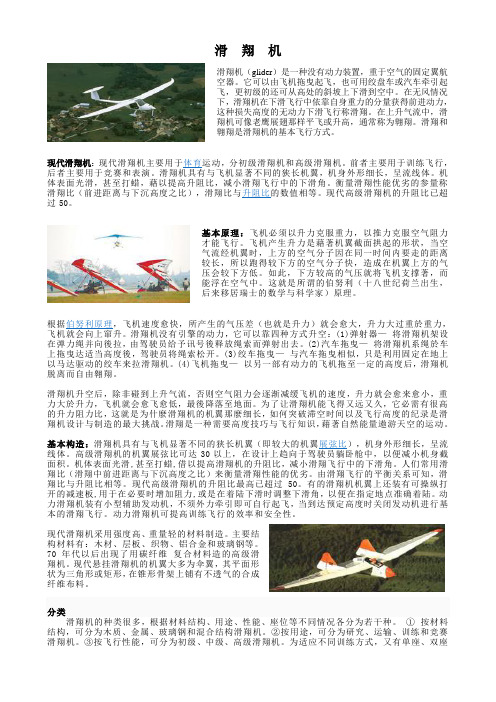
滑翔机滑翔机(glider)是一种没有动力装置,重于空气的固定翼航空器。
它可以由飞机拖曳起飞,也可用绞盘车或汽车牵引起飞,更初级的还可从高处的斜坡上下滑到空中。
在无风情况下,滑翔机在下滑飞行中依靠自身重力的分量获得前进动力,这种损失高度的无动力下滑飞行称滑翔。
在上升气流中,滑翔机可像老鹰展翅那样平飞或升高,通常称为翱翔。
滑翔和翱翔是滑翔机的基本飞行方式。
现代滑翔机:现代滑翔机主要用于体育运动,分初级滑翔机和高级滑翔机。
前者主要用于训练飞行,后者主要用于竞赛和表演。
滑翔机具有与飞机显著不同的狭长机翼,机身外形细长,呈流线体。
机体表面光滑,甚至打蜡,藉以提高升阻比,减小滑翔飞行中的下滑角。
衡量滑翔性能优劣的参量称滑翔比(前进距离与下沉高度之比),滑翔比与升阻比的数值相等。
现代高级滑翔机的升阻比已超过50。
基本原理:飞机必须以升力克服重力,以推力克服空气阻力才能飞行。
飞机产生升力是藉著机翼截面拱起的形状,当空气流经机翼时,上方的空气分子因在同一时间内要走的距离较长,所以跑得较下方的空气分子快,造成在机翼上方的气压会较下方低。
如此,下方较高的气压就将飞机支撑著,而能浮在空气中。
这就是所谓的伯努利(十八世纪荷兰出生,后来移居瑞士的数学与科学家)原理。
根据伯努利原理,飞机速度愈快,所产生的气压差(也就是升力)就会愈大,升力大过重於重力,飞机就会向上窜升。
滑翔机没有引擎的动力,它可以靠四种方式升空:(1)弹射器—将滑翔机架设在弹力绳并向後拉,由驾驶员给予讯号後释放绳索而弹射出去。
(2)汽车拖曳—将滑翔机系绳於车上拖曳达适当高度後,驾驶员将绳索松开。
(3)绞车拖曳—与汽车拖曳相似,只是利用固定在地上以马达驱动的绞车来拉滑翔机。
(4)飞机拖曳—以另一部有动力的飞机拖至一定的高度后,滑翔机脱离而自由翱翔。
滑翔机升空后,除非碰到上升气流,否则空气阻力会逐渐减缓飞机的速度,升力就会愈来愈小,重力大於升力,飞机就会愈飞愈低,最後降落至地面。

沈航二号轻型固定翼飞机设计指导老师:邓忠林设计者:学号:班级:S201202超轻型飞机的设计主要包括总体外形设计机身设计尾翼设计机翼设计飞机的操纵系统渲染效果图简介:超轻型飞机是按重量分类中最轻的一类飞机。
超轻型飞机有许多特点,它的主要特点体现在“超轻”二字上,那就是结构简单、起降方便、低空低速性能好、驾驶容易、运输使用和维护方便、经济安全等,是一种易普及推广的大众航空器。
超轻型飞机属民用航空类。
主要种类:超轻型固定翼飞机超轻型旋翼飞机超轻型三角翼飞机超轻型直升飞机本作品属于超轻型固定翼飞机,适合一般机场起降,采用复合材料制造,轻便,绿色。
轻型飞机总体外形设计二维图纸俯视图侧视图主视图利用SolidWorks绘的三维实体“沈航二号”一:飞机主体结构二,机翼结构设计1,机翼的功用:机翼是飞机的一个重要部件,它的主要功用是产生升力,此外还使飞机具有一定的横测安定性和操纵性。
为了使机翼更好的完成它在空气动力方面的各种功效,常在它的前缘,后缘安装有襟翼,副翼,扰流片等各种副翼。
机翼上的集中载荷和分布载荷:q a—气动分布载荷; q c—质量分布载荷;襟翼机身支反力。
机翼在外载作用下的剪力,弯矩,扭矩图。
Q—机翼的剪力图; M—机翼的弯矩图; M t ---机翼的扭矩图。
2,机翼外形机翼外形对于飞机的气动性能和结构性能有重要的影响,因此选择合理的机翼平面形状是非常重要的。
该轻型飞机的机翼剖面形状是平凸翼型,结构简单,便与生产,而且气动特性比较好,所以在某些低速飞机上应用较多。
3,机翼的受力构件机翼的受力构件包括内部的骨架和外部的蒙皮以及与机身连接的接头,骨架由纵向元件和横向元件组成,纵向元件有翼梁,长桁,纵墙,横向元件有翼肋。
该轻型飞机采用的布局是:纵向元件包括翼梁,纵墙,横向元件是翼肋。
A,翼梁翼梁是飞机中的主要受力构件,它承受机翼的剪力和弯矩。
翼梁主要由上下缘条和腹板组成,缘条承受由弯矩而产生的拉,压轴向力;腹板承受剪切力。

THE ROTOR BLADE (B-7)To build the rotor, you must first build yourself the BLADE WORK-BENCH. First, buy and assemble in one room all materials mentioned in the List of Materials. Take the 2"x8" board and nail it onto a 2"x10" to form a 'T', as shown in the Sketch 1. Use 5" nails, spacing them 12" apart. Make 2"x4" legs and brace-boards and nail them onto the 2x10 two feet from each end. If your floor is not exactly level, put shims under the legs so the Bench does not rock. Put the level on top of the Work-Bench and make sure that its upper surface is: (1) level in all directions, (2) does not bow in either direction and (3) has no twist. Plane or sand the surface until it is as flat as a good carpenter's level can measure. Spread the wax paper on top of the Bench and tack it with thumb tacks on the front side.Cut two strips of pine 2"x2"x10' to be used as pressure-pads for gluing operation. Have a roll of wax paper, small nails and brads, Weldwood glue, your shop tools, a minimum of 16 six-inch "C" clamps and a putty knife on hand. You are now ready to go to work. All components are machined or cut to size before gluing begins. First, prepare the steel spars according to the Drawing: bend 3" of its butt end up 4 degrees; drill and countersink the holes for wood screws. Note the 3/16" locating hole for the Nose Weight. Do not drill six 1/4" holes, nor two 3/8" holes at the root; they are drilled on assembly later. Be sure to prime-coat the steel spars to prevent future corrosion. The upper retention straps may be prepared at the same time, priming and bending their ends 4 degrees up.Cut the leading edge strip 3/4"xl"x10', plane and mark the side to be glued. Cut the wood spar to size; note the taper of 7 degrees chord-wise and 2 1/2" to 1" taper spanwise. To make sure that it is absolutely square, saw it to a "chalk line" and plane true. Make it oversize in length. Cut root and tip filler-blocks on a 7 degree taper, make oversize in width and length, to be fitted later. Do not cut 4 1/2" bevel at the root yet, leaving the end square.Leave the lower and upper skin covers also overlength. If your lumber yard cannot supply you with 1/8" plywood in 10 ft lengths, you may join several shorter lengths together using the "scarf Joint" shown in the Sketch 2, or order a set of 10 ft skins from the Bensen factory. Cut the front edge of the upper cover to a "Chalk line" and plane straight. Its rear edge is cut on a 7 degree bevel and planed to a feather edge. The lower cover is cut rectangular for the time being, 1/4" oversize in width. The taper and reflex bevel will be cut later.Now all parts are assembled and fitted together in the following manner:Place the leading edge strip on top of the wax paper flush with the front edge of the bench. Align its rear edge marked for gluing to a chalk-line on the bench to assure straightness, and tack it in place with a few nails to the bench. Now place the Wood Spar in position butted against the leading edge strip. Slide the Root Filler Block into position under it and scribe a line on the Filler Block along the rear edge of the spar. Remove it and saw on line. Place the Block back in place, plane the top if necessary to flush with wood spar. Use the same procedure with the Tip Filler.1Now lay the top cover in position; check all points for close fit. If satisfactory, remove it, the wood spar and the filler blocks. The blade is now ready for gluing.In first gluing operation, spread a thin coat of glue full length of the wood spar on rear 1/2 inch of bottom, and a thin coat of glue on the joining surface of the lower cover. Push the spar in place against the Leading Edge, and anchor with several small brads through the Spar into the Lower Cover. Root and Tip Filler Blocks are next. Put a thin coat of glue on their bottom and on the lower cover where they join; use a few small brads to anchor.The Top Cover is next. Spread a thin coat of glue where the cover joins the Wood Spar; on full length of the 1" scarf joint; on the area of filler block contact; on top of spar; both filler blocks; and the Lower Cover where it forms a scarf joint with the Upper Cover. Lay the Top Cover in place freely; do not force it into position as it may cause the blade to twist later. When properly located, anchor with a few small brads or wire nails.Now apply the Pressure Strips with 'C' clamps. First lay a length of wax paper on top of the blade, then lay one 2"x2"xl0' strip over the wood spar just rear of the leading edge; clamp with 8 or more 'C' clamps evenly tightened. Lay the other 2"x2"xl0' strip so its rear edge is flush with the rear edge of the Top Cover. Clamp evenly as the front strip. Wipe off all excess glue that squeezes out at seams. Now remove the Leading Edge. Again clean off thoroughly all excess glue from the strip and the front face of the wood spar.Let the blade set for at least 10 hours or more with room temperature over 70 degrees and humidity of 50 percent or less.The Leading Edge is then glued in place to the Wood Spar. Pressure on the leading edge strap is applied either by nailing through the strip into the wood spar, or by using 2" long wood screws spaced 12" apart. Lead holes must be drilled for either. After the glue has dried, nails or screws are removed, holes drilled oversize to accomodate 3/16" hard-wood dowels 2" long, which are inserted 12" apart and glued in place.The blade may now be removed from the bench. All that remains now is to glue the Upper Retention Filler Pad. It may be held in place until the glue dries with two clamps with wood strips for pressure pads.Let the blade season for several days in warm dry air to remove all glue moisture. Metal spars can then be screwed in place. Be sure to drill lead holes for the wood screws about ?" deep. Diameter of the lead holes should be about half of the screw diameter. A rubber-type adhesive may be used under the spar to assure a better bond with the wood, but not absolutely necessary.Root and tip ends are now cut and sanded to shape. Excess piec es sawed off at the ends are used as glue test-samples. Break them at glue joints: all joints should pull wood. If they part at glue surfaces, the blade may be unsound mechanically and should be either rebuilt or discarded.Use the leading edge as your guide to saw the blade to proper width. Then bank on the bottom of blade and saw the 7 degree reflex bevel on the trailing edge.2Now shape the leading edge by planing and sanding or by multiple-step saw cuts, or both, Make an Airfoil Template form the Drawing to constantly check the airfoil contour. Remember, round leading edges, sharp trailing edges and smooth surfaces are essential to good aero dynamic performance.Fill large depressions, cracks and openings around the spar with plastic wood; or a mixture of plastic v/ood and primer-surfacer. Use a sanding block rather than free hand for all contour sanding. Blades should then be sealed with a thinned mixture of good quality of wood sealer.Clamp the Upper Retention strip in place. 3e sure the distance between the spar and the strap is exactly 3/4" and they are parallel. This is quite important, bacause the Hub Plate is also 3/4" thick aluminum piece, and the steel straps must go from wood to aluminum without wedging or pinching. Drill six 1/3" holes in one setting and bolt together as shown on the print.You are now ready to install the Nose Weight and the Trim Tab.The Nose Weight consists of a 5" wide, 0.062" thick steel strip bent in U-shape, filled with plumber's solder and attached to the leading edge of the blade 24" from the tip. Use the Drawing as your template of the shape of the steel strip. Weld or braze the end plates on the sides of the U and the retention posts to hold the solder firmly in place. After they are filled with solder, the weights should weigh exactly 29 oz apiece. Use the 9th hole from the tip in the steel spar to locate your first outboard hole in the Nose Weight. The other two holes will straddle the No. 10 hole. Drill through with No. 11 (or 3/16") drill and use #10-32 (or 3/16") bolts to clamp the weight on the blade, Thin self-locking nuts, or shear nuts with lock-washers should be used and later may be covered with balsa streamlined caps. But you can fly also with the bolts unfaired.The Trim Tabs are made of 0.020" to 0.030" thick aluminum sheet cut 2"x6" and located 6" from the tip of the blade. One inch of its width overhangs the trailing edge of the blade and is bent up 10 degrees. To assure a better bond, glue it on with a rubber-type adhesive and secure it with three flush rivets.Finally, sand down the blade thoroughly, leaving no ridges, nor depressions, especially on the upper surface, round off the tip as shown, and cover the blade with the primer-surfacer. When completely dry, sand down with block and fine sandpaper and cover again with the primer-surfacer. After another thorough sanding, paint it with two coats of hard-gloss exterior synthetic enamel.For a still more durable finish, you may cover the leading and trailing edges of your blades with aircraft fabric, or Fiberglas. That type of finish will last several years. However, if you never used aircraft dope, or polyesters, before, you will be better off to stick to the simpler procedure.Your rotor blade is now ready for assembly. If it was correctly built, it will weigh 14 pounds fully assembled and its center of gravity will be at the station 57.Notice that the inboard ends of the steel straps are not drilled yet. They will be drilled "on assembly" later, when attached onto the Rotor Hub.3If you made any mistakes on one blade, which might affect its weight distribution, or stiffness, you must repeat them on the second blade, or else start anew. It is very important that the two blades are exactly alike, as you will see from the instructions on "Rotor Tracking". The better work you do when building the blades, the fewer problems you will have when you start flying.One last word of caution. Take good care of your rotor blades, because they are what keeps you in the air when you fly. Keep them out of the rain, snow and sandstorms. When storing them for a long time, leave them lying flat on the work-bench in a dry cool place. Watch for signs of rusting or severe warping, which usually come with excessive humidity.Remember, rotor blades are your wings. Protect them as you do your arms and legs. If you do, they will give you many years of efficient and trouble-free service.LIST OF CONSTRUCTION MATERIALS1 Qt. Primer-Surfacer1 Lb. Weldwood Glue1 Roll of Wax Paper1 Pt. of Zinc Chromate Primer,Red Lead Primer of Alum. Paint1 Pt, of good Wood Sealer1/4 Lb. of Plastic Wood1 Small Box of Thumb Tacks3 Lbs Plumber's Solder Sticks1 Qt. Good Exterior Enamel1 Box of Wire Nails1 Box of bradsList of materials for one set, complete? ?? ???????? ??. ??????????? ????????? ?????? ?????????7-103-001 2 Main Spars, 1018 Steel* 1/8"x2"x118"7-103-002 2 Upper Retention Straps, 1018 1/8"x2"x13"7-103-003 2 Wood spars, Plywood, 5-ply 1/2"x21/2"10'7-103-004 2 Leading Edges, White Pine 3/4"x11/4"x10'7-103-005 2 Upper Skin Covers, 3 -ply Plywood 1/8"x5 3/8"x10'7-103-006 2 Lower Skin Covers, 3-ply Plywood 1/8 x6"/10'7-103-007 2 Upper Filler Pads, 5-ply Plywood 1/2"x3"x13"7-103-008 2 Root Filler Blocks, 3-ply Plywood 3/8"x3"x20"7-103-009 2 Tip Filler Blocks, 3-ply Plywood 3/8"x3"x6"7-103-013 2 Aluminum Trim Tabs .030"x2"x6"7-103-01416 2 Nose Weights, 1018 Steel gage 5"x9"7-103-015 116 Screws, Flat-Head #6x1/2"AN 4-14 12 Bolts for Blade Root 1/4"x1 1/16" gripAN 960-416 12 Washers" 1/4"AN 363-428 12 Stop Nuts " 1/4"-28AN 23-19 6 Clevis Bolts for Nose Weights 3/16"x7/8" gripAN 364-1032 6 Stop Nuts, Thin #10-32AN 6-15 4 Bolts, Blade-to-Hub 3/8"x1 1/16" gripAN 310-6 4 Nuts, castellated " 3/8"-24AN 960-616 8 Washers " 3/8"4 Cotter Pins " 1/16"x1"AN 456-A4-4 6 Rivets, Aluminum, soft 1/8"x 1/4"4。
【原创】无人机概述系列(一)--固定翼的分类
作者:天途教育培训师吴星宇
固定翼作为无人机系统里三大飞行平台之一,针对不同的使用环境自然有不同的结构形态,今天我们来了解下行业中常见的固定翼类型。
一、常规布局所谓常规布局就是水平尾翼在主翼之后,除了水平尾翼的位置,主翼的位置不同也对飞机的布局产生影响:(一)上单翼指主翼安装位置在机身上方,具有较高的稳定性,但灵活性较差。
(二)中单翼指主翼安装位置在机身中部,兼具灵活性和稳定性(三)下单翼指主翼安装位置在机身下方,具有较高的灵活性,但稳定性较差。
二、鸭式布局鸭式布局为水平尾翼位于机翼之前,具有在大机动动作下,较好的空气动力性能。
三、无尾布局只有一对机翼,根据飞机本身应用环境,决定是否装有垂直尾翼。
用Auto CAD绘制模型飞机加工图(上)橙子喜欢自己设计制作模型飞机的模友,大都离不开一些电脑辅助设计软件,如AutoCAD、Profili、Design foil、CATIA、AAA(Advanced.Aircraft.Analysis)等。
它们可用于绘制平面图、构建三维模型、提供翼型数据以及进行模型飞机的总体设计分析等。
掌握好其中的AutoCAD、Profili和AAA三种软件,即可完成大多数模型飞机的设计制作。
如今数控激光雕刻机应用广泛,详细的加工图纸会给模型飞机的制作带来很大方便,并能保证制作精度和美观程度。
不过很多模友仅能根据设计自己画出模型飞机三面图(图1),而不知如何将其转化为详细的加工制作图。
下面笔者以一架双尾撑布局的固定翼模型飞机(采用倒V形尾翼、上单翼、发动机推进式设计)为例,介绍自己依据三面图用AutoCAD绘制加工图的心得和体会。
图1 模型飞机的三面图首先要保证三面图准确、清晰;然后根据经验和简单计算,确定每个部位的材料和尺寸;之后便可开始绘制加工图了,主要分为机翼、机身和尾翼三个部分。
机翼图2 选择翼型对于常规的固定翼模型飞机,机翼通常由翼肋、主梁、后梁(又称后墙)和前缘定位条构成。
翼肋图纸可通过一些专门的翼型软件得到,如用Profili软件产生一个翼型文件,再导入AutoCAD中。
具体步骤如下:打开Profili软件,如图2所示,点击键1,从出现的对话框中选择所需翼型(这里选NACA4412);点击键2,在弹出的对话框中输入图3所示的各选项,按OK键确定;待翼型图纸弹出后(图4),点键3“保存为DXF格式”(默认格式)到自建的文件夹内,即可得到所需翼型的CAD文件。
该翼型的弦长为100mm,可按实际需要缩放。
图3 设置翼型参数图4 保存为DXF格式用AutoCAD打开已有模型飞机的三面图,把翼型图纸复制上去(图1),准备绘制翼肋加工图。
绘制前先要了解CAD中的几个常用工具(见图5注释)。