sae,j1939协议下载
- 格式:docx
- 大小:21.99 KB
- 文档页数:12


SURFACE3.3.2 Arbitrary Address Capable CA (6)3.4 Types of CAs (6)3.4.1 Standard CAs (6)3.4.2 Diagnostic/Development Tool CAs (6)3.4.3 Network Interconnection CAs (6)4. Technical Requirements (7)4.1 NAME and Address Requirements (7)4.1.1 NAME (8)4.1.1.1 NAME Fields (9)4.1.1.2 Arbitrary Address Capable Field (10)4.1.1.3 Industry Group Field (10)4.1.1.4 Vehicle System Instance Field (10)4.1.1.5 Vehicle System Field (10)4.1.1.6 Reserved Field (10)4.1.1.7 Function Field (10)4.1.1.8 Function Instance Field (10)4.1.1.9 ECU Instance Field (11)4.1.1.10 Manufacturer Code Field (11)4.1.1.11 Identity Number Field (11)4.1.1.12 Dependencies in the NAME Fields (11)4.1.2 Addresses (12)4.1.2.1 The 254 Address (12)4.1.2.2 The 255 Address (12)4.2 Network Management Procedure (13)4.2.1 Request Message (PGN 59904) for Address Claimed (PGN 60928) (13)4.2.2 Address Claimed / Cannot Claim (PGN 60928) (14)4.2.2.1 Address Claimed Message (15)4.2.2.2 NAME of Controller Application (15)4.2.2.3 Cannot Claim Address (15)4.2.3 Commanded Address (PGN 65240) (16)4.2.3.1 Commanded Address Message (16)4.2.3.2 NAME of Commanded Address Target (17)4.2.3.3 Address Assignment (new source address) (17)4.2.4 Working Sets (17)4.2.4.1 Application Notes (18)4.2.4.1.1 Message sequence (18)4.2.4.1.2 Working Set Member Message Spacing (18)4.2.4.1.3 Compatibility with Conventional Network Processes (18)4.2.4.1.4 Constraints on Working Set Membership (19)4.2.4.1.5 Configuration Changes (19)4.2.4.1.6 Source Address Changes (19)4.2.4.1.7 Missing Working Set Members (19)4.2.4.2 Working Set Master Message – WSMSTR (PGN 65037) (20)4.2.4.3 Number of Members (20)4.2.4.4 Working Set Member Message – WSMEM (PGN 65036) (20)4.2.4.5 NAME of Working Set Member (21)4.3 Network Error Management (21)4.3.1 Cannot Claim Address (21)4.4 Address Claim and CA Initialization procedure (21)4.4.1 Address Claim Prioritization (22)4.4.2 Address Claim Requirements (22)4.4.2.1 Requirements for Requests for Address Claimed (22)4.4.3 Address Claim Initialization Rules (22)4.4.3.1 Response to a Request for Address Claimed sent to the global address (22)4.4.3.2 Response to a Request for Address Claimed sent to a specific address (22)4.4.3.3 Response to Address Claims of Own Address (23)4.4.3.4 Contention for an Address (23)4.4.4 Message Sequences for Initialization (23)4.4.4.1 Message sequences for initialization for all CAs on the network (23)4.4.4.2 Potential Identical Identifiers in Network Management Messages (23)4.4.4.3 Address Claim Bus Collision Management (24)4.4.4.4 A CA which is Unable to Successfully Obtain an Address (24)4.4.5 Requests for Address Claimed for Self-Configurable Addressing CAs (24)4.4.5.1 Technical Note Regarding Multiple Self-Configurable Addressing CAs (25)4.4.5.2 CAs Not Permanently Connected to the Network (25)4.4.6 Construction of Address to NAME Association Tables (25)4.5 Minimum Network Management Functionality (25)4.5.1 Reaction to Power Supply and Other Related ECU Disturbances (25)4.5.2 Minimum Network Management Capability (26)4.5.2.1 Request for Address Claimed Message (26)4.5.2.2 Address Claimed Message before Using a Source Address (26)4.5.2.3 Disruption of the Network During Connection or Disconnection of an ECU (26)4.5.2.4 Continuity of Addresses Across Power-down and Power-up Cycles (26)Appendix A: Initialization Sequence Timing Diagrams (27)FIGURE A1 - Initialization of A CA with Address Claim and No Contention (27)FIGURE A2 - Initialization of an ECU Where Two Single Address CAs Attempt To Claim the Same Address But Not Simultaneously (27)FIGURE A3 - Initialization of a CA Where NAME A Is Less Than NAME B and CA B is ArbitraryAddress Capable (28)FIGURE A4 - Initialization of a CA with Two CAs Attempting to Claim the Same AddressSimultaneously (28)1Single Address CAs with addresses in the 0-127 and 248-253 ranges may omit the 250 ms delay (29)FIGURE A5 - Initialization of an Arbitrary Address Capable CA with No Contention (29)FIGURE A6 - Initialization of an Arbitrary Address Capable CA with a Request for Address Claimed Sent to the Global Address (29)FIGURE A7 - Initialization of a Single Address CA with a Request for Address Claimed Where Address Is In Use (30)FIGURE A8 - Response to a Request for Address Claimed by a CA which has Been EarlierUnsuccessful In Claiming an Address (30)FIGURE A9 - Commanding an Address of a CA which does not have an Address and Supports the Commanded Address Message (31)FIGURE A10 - Commanding an Address of a CA which does not have an Address and theCommanded CA Does Not Support A Commanded Address Message (31)Appendix B Summary of Requirements and Capabilities of CAs (32)Appendix C NAME Examples (33)C.1 NAME Examples (33)C.1.1 A Single ECU with a CA Serving an Engine on an On-Highway Heavy-Duty Truck.33 C.1.2 Brakes on the second trailer of heavy-duty truck (33)SAE J1939-81 May 2003C.1.3 Agricultural planters with separate Section Controls (34)Appendix D: State Transition Diagrams for Address Claiming Processes (35)FIGURE D1 - State Transition Diagram for Initialization of Arbitrary Address Capable CAs (36)FIGURE D2 - State Transition Diagram for Initialization of Single Address CAs (37)FIGURE D3 - State Transition Diagram for Response of a CA to the Commanded Address Message381. ScopeThese SAE Recommended Practices are intended for light and heavy duty vehicles used on or off road as well as appropriate stationary applications which use vehicle derived components (e. g. generator sets). Vehicles of interest include, but are not limited to on and off highway trucks and their trailers; construction equipment; and agricultural equipment and implements.The purpose of these documents is to provide an open interconnect system for electronic systems. It is the intention of these documents to allow Electronic Control Units to communicate with each other by providing a standard architecture.Network management in the SAE J1939 network is concerned with the management of source addresses and the association of those addresses with an actual function and with the detection and reporting of network related errors. Due to the nature of management of source addresses, network management also specifies initialization processes, requirements for reaction to brief power outages and minimum requirements for ECUs on the network.2. ReferencesGeneral information regarding this series of recommended practices is found in SAE J1939.2.1 Applicable PublicationsAvailable from SAE, 400 Commonwealth Drive, Warrendale, PA 15096-0001.2.1.1 SAE PublicationsSAE J1939 - Recommended Practice for Serial Control and Communications Vehicle NetworkSAE J1939-21 - Data Link LayerSAE J1939-31 - Recommended Practice for Serial Control and Communications Vehicle Network - Part 31-Network Layer3 DefinitionsSee SAE J1939 top level document for definition of terms not defined in this document.3.1 Terminology used in network managementTerms are defined in SAE J1939 for use in the context of this document.3.2 Controller Application (CA)For the purposes of this document, a controller is made up of the software and the hardware within an Electronic Control Unit (ECU) that performs a particular control function. The software within a particular controller is the “Controller Application” (CA). An ECU may serve as one or more controllers and hence may contain one or more CAs. Each CA will have one address and an associated NAME in order to communicate on the J1939 network.3.3 Address Configuration and Capability3.3.2 Arbitrary Address Capable CAAn Arbitrary Address Capable CA is one that can select its source address from any appropriate SA (including those in the range 128 to 247 inclusive) based on internal algorithms, and then claim that address. This CA, in cases of address conflict, is also able to re-calculate its address and re-claim (unless all 120 of the addresses between 128 and 247 are used). The value in the Arbitrary Address Capable field in the NAME (See Section 4.1.1.2) indicates whether or not a CA has this capability. This capability is needed particularly for CAs that are expected to have multiple instances of the same device on a single vehicle. In these cases, the Arbitrary Address Capable CA will be the one to lose arbitration for a Preferred Address since the setting of the Arbitrary Address Capable bit in its NAME lowers its priority for address claim. This is correct behavior since its ability to operate correctly on the network will not be affected by the loss of arbitration. Note that if its function is one that would normally use a Preferred Address in the lower 128, it will claim that address first. Only upon losing arbitration during Address Claim will it claim an unused address from the range above 128.3.4 Types of CAsFor the purposes of network management, there are three types of CAs: Standard, Diagnostic/Development Tools, and Network Interconnection CAs.3.4.1 Standard CAsStandard CAs are those CAs whose primary function is not that of network interconnection or of programming, diagnosing, or otherwise functioning as tools or network interconnection CAs.Standard CAs include those used for engines, transmissions, brakes, virtual terminals, instrument clusters, and vehicle navigation. Data loggers and recorders are also examples of standard CAs but if these CAs assume diagnostic tool functions then they should meet requirements of diagnostic tool CAs. Standard CAs do not have the ability to modify the source addresses of any other CAs except as a result of the address claiming process.Standard CAs may or may not possess any of the addressing capabilities listed in section 3.3. It is not the intent of this document to require a particular address configuration capability for any Standard CA.3.4.2 Diagnostic/Development Tool CAsDiagnostic and Development Tool CAs are those which are connected to a particular SAE J1939 subnetwork for the purpose of analyzing, debugging, developing or monitoring any CA on the subnetwork or the operation of the subnetwork itself. Although these tools are not expected to be permanently attached to a subnetwork, such a tool may well be a permanent part of a particular vehicle or craft. In either case, the capabilities of these tools are more extensive than those of Standard CAs. They are primarily designed to interact with other CAs on the network and have no other external functionality (a diagnostic tool, for example, is not expected to provide torque, plant beans, or brake a vehicle).These tools may be intended as proprietary tools to operate on or in a given manufacturer's ECUs. They may be intended as a general-purpose tool to operate on ECUs provided by several manufacturers. Or they may be intended to work primarily on the network itself, providing network integration services for system integrators and OEM vehicle manufacturers.3.4.3 Network Interconnection CAsNetwork Interconnection CAs are those that exist primarily for the purpose of interconnecting networks or subnetworks. They primarily consist of repeaters, bridges, routers and gateways. In one manner or another, all network interconnection CAs forward messages from one subnetwork to another.Subnetworks interconnected by Network Interconnection CAs may have the same protocol, as in two SAE J1939 subnetworks in the same vehicle; they may have different protocols, such as from SAE J1708/J1587 to SAE J1939, or may be interconnected off-vehicle subnetworks, such as satellite link, token ring or cellular modem.Network Interconnection CAs serving as gateways translate from SAE J1939 subnetworks to various other networks. This document will deal only with the SAE J1939 portions of those CAs.4. Technical RequirementsThe Network Management layer in an SAE J1939 network provides the definitions and procedures necessary to uniquely identify CAs on the network, manage the assignment of addresses, and manage network errors.♦ Each CA must be capable of providing its unique 64-bit NAME. The rules for creating this NAME, associating it with an address and the ability or non-ability to change that address are presented in section 4.1 “NAME and Address Requirements”.♦ CAs must successfully claim an address according to the procedures explained in section 4.2 “Network Management Procedure” prior to sending any other messages on the network. Multiple ECUs and/or CAs can work together to perform functions but must follow the rules in section 4.2.4.♦ The inability to successfully claim an address according to the procedure must be handled and reported to the network in a standard way expressed in section 4.3.♦ Network initialization sequences associated with the address claiming process are described in section4.4.♦ A minimum set of network management requirements, including required responses to power interruptions are listed in section 4.5.4.1 NAME and Address RequirementsAddresses are used within SAE J1939 networks to provide uniqueness to message identifiers and to allow the source of a message to be determined. (Addresses are sometimes referred to as “Source Addresses” indicating the latter use). Address claim messages, which contain both a source address and a NAME, are used to associate a NAME with a particular address on the network.Every CA that transmits messages on a SAE J1939 network must have a NAME and successfully acquire an Address before the CA may transmit normal network traffic. The NAME serves two purposes, first, to provide a functional description of the CA (e.g. Engine Number 1, Engine Number 2, Transmission Number 1, Anti-Lock Brake System 1) and second, to provide a numerical value that may be used in arbitration for addresses. Addresses are used within SAE J1939 networks to provide uniqueness to message identifiers and to allow the source of a message to be determined. (Addresses are sometimes referred to as “Source Addresses” indicating the latter use). Address claim messages, which contain both a source address and a NAME, are used to associate a NAME with a particular address on the network. The association of an address with a unique NAME (4.1.1) also provides means to associate an address with a CA. Manufacturers of ECUs and integrators of networks must assure that the NAMEs of all CAs intended to transmit on a particular network are unique.4.2.2 Address Claimed / Cannot Claim (PGN 60928)The Address Claimed PGN may be used in two ways, to claim an address, and to announce that a CA was unable to claim an address. The former case is referred to in 4.2.2.1 as the Address Claimed message, and the latter in 4.2.2.2 as the Cannot Claim Address message. The Address Claimed message is used by any CA to either respond to a received request message for the Address Claimed message or to simply claim a single address on the network. CAs must issue it during initialization of a network or when attaching to a running network. If a CA receives an Address Claimed message claiming its own source address, it should compare the NAME that was received in the Address Claimed message with its own NAME and determine which CA has a higher priority NAME (lower numeric value as described in 4.4.3.3). If the CA receiving the Address Claim determines that it has the higher priority NAME it may then transmit an Address Claimed message containing its NAME and address. However if it has the lower priority NAME it should either attempt to claim a different address or send a Cannot Claim Address message. A CA that loses address arbitration in this manner and is in the process of sending a transport protocol message should immediately cease sending the transport protocol message and should not send a Transport Protocol Abort. Receivers of the transport protocol message must detect the interruption through the normal transport protocol timeout process as specified in J1939-21 (1.25 sec.) Queued transport protocol frames should cease within the timeout and constraints given in J1939-21, 5.10.3.4 (50 ms).A CA may send the Cannot Claim Address message (See 4.2.2.3) or a Request for Address Claim using the null address as a source address (See 4.2.1) provided it has attempted the address claim and without having successfully claimed an address. A network interconnection CA may not use its own address in communications on the network until it has successfully claimed that address. Handling messages of other CAs is a special case for network interconnection devices. Network interconnection devices acting entirely as repeaters may pass messages bearing the originator’s Source Address before claiming their own addresses (For further requirements for network interconnection devices see SAE J1939-31).Configuration of networks with multiple bridges may create significant delay between transmission and reception of address claims that traverse the bridges. The 250 ms delay may not be adequate in these systems to prevent further arbitration after a CA has successfully claimed an address.Once a CA has successfully claimed an address, it may begin transmitting other messages on the network and respond to any further Requests for Address Claim.No valid claim may be made for Address 254, the null address. An Address Claimed message sent with address 254 as the source address is a Cannot Claim Address message (see 4.2.2.2).The Address Claimed message should always be sent to the global address (255) to provide all ECUs on the network the information to maintain a current address to NAME correspondence. The Address Claimed message should be sent to the global address (255) even when requested in a destination specific message. The Address Claimed message is an exception to the requirements on request messages specified in SAE J1939-21. (SAE J1939-21 defines that a request message that is directed to a specific address be responded to with the destination set to the requester.)Appendix D: State Transition Diagrams for Address Claiming ProcessesState transition diagrams are presented in Figures D1, D2, and D3 for address claiming processes. Processes are presented for initialization of both single address capable and arbitrary address capable ECUs. These diagrams are intended to clarify processes outlined throughout this specification. The specifications in the paragraphs of this document have precedence in the event of any discrepancy between the text and figures.States are shown in the diagrams as circles with the title of the state enclosed in the circle. Arrows leaving the states have associated text describing the event that triggers transition from the state. The triggering event text is followed by a slash (/). In some cases, there is an action that takes place after the trigger on entering the next state. The transition action is associated with the arrows leaving a state and is text that is not followed by a slash (/).Rationale - Since the initial publication of SAE J1939-81 in 1997 the other layers of SAE J1939 have been further defined and the proposed uses of SAE J1939 have evolved beyond those foreseen at that time. Two major concepts have been added. Controller Applications introduces the idea of multiple applications running in one module. Working Sets addresses the use of multiple modules to perform a single coordinated function.The definitions of all terms have been expanded and made consistent with other documents. Minimum requirements were updated. Examples have been improved and Appendices added.Relationship of SAE to ISO Standard - Not Applicable.Application - These Recommended Practices are intended for light and heavy-duty vehicles used on or off road as well as appropriate stationary applications which use vehicle derived components (e. g. generator sets). Vehicles of interest include, but are not limited to: on and off highway trucks and their trailers; construction equipment; and agricultural equipment and implements.The purpose of these Recommended Practices is to provide an open interconnect system for electronic systems. It is the intention of these recommended practices to allow Electronic Control Units to communicate with each other by providing a standard architecture.Network management in the SAE J1939 network is concerned with the management of source addresses and the association of those addresses with an actual functional and with the detection and reporting of network related errors. Due to the nature of management of source addresses, network management also specifies initialization processes, requirements for reaction to brief power outages, and minimum requirements for ECUs on the network.Reference SectionSAE J1587 - Joint SAE/TMC Electronic Data Interchange Between Microcomputer Systems in Heavy-Duty Vehicle ApplicationsSAE J1939 - Recommended Practice for Serial Control and Communications Vehicle NetworkSAE J1939-21 - Data Link LayerSAE J1939-31 - Recommended Practice for Serial Control and Communications Vehicle Network - Part 31-Network LayerDeveloped by the SAE Truck and Bus Control and Communications Subcommittee Sponsored by the SAE Truck and Bus Electrical and Electronics Committee。

J1939协议一、协议目的本协议旨在规范和定义J1939协议的通信规则和数据格式,以便确保各种车辆和设备之间的互操作性和数据交换的一致性。
二、协议范围本协议适用于使用J1939协议进行通信的各种车辆和设备,包括但不限于商用车辆、农业机械、建筑设备、发电机组、船舶和工业自动化设备等。
三、术语和定义1. J1939协议:一种用于车辆和设备之间的通信的协议,基于CAN总线技术。
2. 数据帧:J1939协议中的数据传输单元,包含源地址、目标地址、数据内容等信息。
3. 参数组:J1939协议中的一种数据结构,用于封装和传输特定的数据项。
4. PGN:参数组号码(Parameter Group Number),用于唯一标识一个参数组。
5. SPN:信号参数号码(Suspect Parameter Number),用于唯一标识一个参数组中的一个信号。
四、协议规则1. 数据帧格式1.1 数据帧由CAN总线上的标准帧组成,帧格式为11位标识符。
1.2 数据帧包含11位标识符、数据长度代码(DLC)、数据字节和CRC校验码。
1.3 数据帧的标识符中包含源地址、优先级、数据页、PGN等信息。
1.4 数据帧的DLC定义了数据帧中数据字节的数量。
1.5 数据帧的CRC校验码用于验证数据的完整性。
2. 参数组格式2.1 参数组由一个PGN和一个或多个SPN组成。
2.2 PGN由18位标识符的前3个字节组成。
2.3 SPN由16位标识符的后两个字节组成。
2.4 参数组中的数据按照大端字节序排列。
3. 数据传输3.1 数据传输通过CAN总线进行。
3.2 数据帧的发送和接收由源地址和目标地址进行控制。
3.3 数据传输的优先级由数据帧的标识符中的优先级字段确定。
3.4 数据传输的频率和时序由应用层协议定义。
4. 错误处理4.1 错误帧:当接收到错误的数据帧时,应立即发送错误帧作为响应。
4.2 错误处理机制:错误处理机制应能够检测和处理数据传输过程中的错误,包括但不限于传输错误、接收错误和校验错误等。
SAE J1939 协议简介(大结局)由于应用层会根据不同的行业和需求有所不同,所以应用层的开发可以参考标准自行研究,关于这个系列,今天是最后一集,我们来讲讲J1939的网络管理层(J1939/81)。
其实任何一种协议单看协议文件都是很枯燥的,但是其实协议软件的开发流程图就隐含在这协议描述中,多看几遍,多读几遍,多琢磨琢磨,在找些参考资料,相信你一定会理解协议中的需求,为你的后续开发扫平障碍。
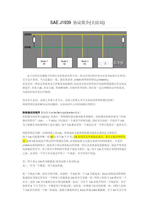
肯定有人会问,总线上有那么多节点,总线上的那么多节点是如何管理和通信的呢?网络管理层就是解决这些问题的。
先来讲讲什么叫控制器应用程序。
控制器应用程序(CA)Controller Application(CA)控制器为电控单元(ECU) 内执行一种特殊控制功能的软件和硬件。
控制器里的软件称为“控制器应用程序”(CA)。
一个ECU 可以执行一个或多个控制功能,因此可以包括一个或多个CA。
为了能够在本标准网络上进行通信,每个CA都必须有一个地址以及一个和它联系在一起的名字。
网络管理层为唯一识别网络上的CA、管理地址分配和网络错误提供必要的定义和程序。
每个CA应能提供唯一的64位名字(8个字节).CA必须首先声明地址成功,然后才能向网络发送,如果CA按地址声明过程声明地址失败,必须按标准方式进行处理并向网络报告。
在采用J1939标准的网络中,地址用于保证消息标识符的唯一性以及表明消息的源地址。
地址声明消息包括地址和名字,用于把名字和网络中的某个地址关联在一起。
每个CA在开始正常的网络通信之前,必须有一个名字并且成功声明了一个地址。
名字有两个用途:其一用于表示CA的功能描述(如发动机1,发动机2)其二,作为一个数值,用于地址仲裁。
把一个地址与唯一的名字相关联,也就把一个地址和一个CA关联起来。
ECU的制造商和网络集成商必须保证所有在一个网络上传输消息CA的名字是唯一的。
网络上的每个CA都应有一个名字,这样CA可以根据它的主要功能被唯一标识。
路面车辆推荐操作规程(被采纳为美国国家标准)SAEJ1939-11:物理层,250K比特/秒,屏蔽双绞线前言本系列SAE推荐操作规程是由卡车及客车电子电气委员会所属的卡车及客车控制及通信小组委员会制定的。
该小组委员会的目标是针对电控单元的需求、设计和使用,提交信息报告、制定推荐操作规程。
这些电控单元在汽车部件之间传递着电子信号和控制信息。
本规程的使用不限于卡车和客车应用,其对于其他的应用也可以提供直接的支持,正如已在建筑及农业设备和固定式的动力系统。
本推荐操作规程的最终目标是形成工业标准,因此可能为适应实际应用和技术进步作出经常性的调整。
目录前言 (1)1 目标 (4)2 参考 (4)2.1 应用出版物 (4)2.1.1 SAE出版物 (4)2.1.2 ISO出版物 (4)2.1.3 军用出版物 (4)2.2 相关出版物 (5)2.2.1 (5)3 网络物理层描述 (5)3.1 物理层 (5)3.2 物理介质 (5)3.3 差动电压 (5)3.4 总线电平 (6)3.5 仲裁期间的总线电平 (6)3.6 一般模式总线电压范围 (6)3.7 总线终端 (6)3.8 内部电阻 (6)3.9 差动内部电阻 (7)3.10 内部电容 (7)3.11 差动内部电容 (7)3.12 位时间 (7)3.13 内部延迟时间 (10)3.14 CAN位时序请求 (11)4 功能性描述 (13)5 电气特性 (13)5.1 子数据 (13)5.1.1 电子控制单元 (13)5.1.1.1 绝对最大额定值 (14)5.1.1.2 直流参数 (14)5.1.1.3 交流参数 (15)5.1.2 总线电压——操作的 (15)5.1.3 静电放电器(ESD) (15)5.1.4 物理层示例电路 (15)5.2 物理媒介参数 (16)5.2.1 总线 (17)5.2.2布局 (17)5.2.3 终端电阻 (17)5.2.4 屏蔽终端 (18)5.3 连结器规定 (18)5.3.1 连接器电子性能要求 (19)5.3.2 连接器机械性要求 (19)6 一致性测试 (20)6.1 ECU的隐性输出 (20)6.2 V CAN-H和V CAN-l的内部电阻 (21)6.3 内部不同电阻 (21)6.4 ECU的隐性输入的阀限 (21)6.5 ECU的显性输出 (22)6.6 ECU的显性输出阀限 (22)6.7 内部延迟时间 (23)7 总线错误的讨论 (23)7.1 网络连接失败 (23)7.2 接点能量或地丢失 (24)7.3 断开遮蔽 (24)7.4 开放和短错误 (24)8 注意 (25)8.1 旁注 (25)附录A 物理层电路范例 (26)A.1 物理层例1 (26)A.2 物理层例2 (26)A.3 物理层例3 (27)附录B 推荐的电缆终端制造过程 (29)B.1 推荐的电缆终端制造过程 (29)附录C 推荐的电缆接合工序 (30)C.1 推荐的电缆接合工序 (30)附录D 推荐的电缆修复工序 (32)D.1 推荐的电缆修复工序 (32)附录: (33)理论基础 (33)SAE标准和ISO标准之间的关系 (33)应用 (33)参考文件 (33)1目标本推荐规程供轻型、中型或重型的车辆或者合适的使用车辆派生部件(如发动机组)的固定设施使用。

路面车辆推荐操作规程(被采纳为美国国家标准)SAEJ1939-11:物理层,250K比特/秒,屏蔽双绞线前言本系列SAE推荐操作规程是由卡车及客车电子电气委员会所属的卡车及客车控制及通信小组委员会制定的。
该小组委员会的目标是针对电控单元的需求、设计和使用,提交信息报告、制定推荐操作规程。
这些电控单元在汽车部件之间传递着电子信号和控制信息。
本规程的使用不限于卡车和客车应用,其对于其他的应用也可以提供直接的支持,正如已在建筑及农业设备和固定式的动力系统。
本推荐操作规程的最终目标是形成工业标准,因此可能为适应实际应用和技术进步作出经常性的调整。
目录前言 (1)1 目标 (6)2 参考 (6)2.1 应用出版物 (6)2.1.1 SAE出版物 (6)2.1.2 ISO出版物 (7)2.1.3 军用出版物 (7)2.2 相关出版物 (7)2.2.1 (7)3 网络物理层描述 (8)3.1 物理层 (8)3.2 物理介质 (8)3.3 差动电压 (8)3.4 总线电平 (8)3.5 仲裁期间的总线电平 (9)3.6 一般模式总线电压范围 (9)3.7 总线终端 (9)3.8 内部电阻 (9)3.9 差动内部电阻 (10)3.10 内部电容 (10)3.11 差动内部电容 (10)3.12 位时间 (10)3.13 内部延迟时间 (13)3.14 CAN位时序请求 (15)4 功能性描述 (17)5 电气特性 (18)5.1 子数据 (18)5.1.1 电子控制单元 (18)5.1.1.1 绝对最大额定值 (19)5.1.1.2 直流参数 (19)5.1.1.3 交流参数 (21)5.1.2 总线电压——操作的 (21)5.1.3 静电放电器(ESD) (21)5.1.4 物理层示例电路 (21)5.2 物理媒介参数 (21)5.2.1 总线 (22)5.2.2 布局 (22)5.2.3 终端电阻 (23)5.2.4 屏蔽终端 (24)5.3 连结器规定 (24)5.3.1 连接器电子性能要求 (25)5.3.2 连接器机械性要求 (26)6 一致性测试 (27)6.1 ECU的隐性输出 (27)6.2 V CAN-H和V CAN-l的内部电阻 (28)6.3 内部不同电阻 (29)6.4 ECU的隐性输入的阀限 (29)6.5 ECU的显性输出 (30)6.6 ECU的显性输出阀限 (30)6.7 内部延迟时间 (31)7 总线错误的讨论 (32)7.1 网络连接失败 (32)7.2 接点能量或地丢失 (32)7.3 断开遮蔽 (32)7.4 开放和短错误 (32)8 注意 (35)8.1 旁注 (35)附录A 物理层电路范例 (36)A.1 物理层例1 (36)A.2 物理层例2 (37)A.3 物理层例3 (38)附录B 推荐的电缆终端制造过程 (40)B.1 推荐的电缆终端制造过程 (40)附录C 推荐的电缆接合工序 (41)C.1 推荐的电缆接合工序 (41)附录D 推荐的电缆修复工序 (44)D.1 推荐的电缆修复工序 (44)附录: (45)理论基础 (45)SAE标准和ISO标准之间的关系 (45)应用 (46)参考文件 (46)1目标本推荐规程供轻型、中型或重型的车辆或者合适的使用车辆派生部件(如发动机组)的固定设施使用。
竭诚为您提供优质文档/双击可除saej1939协议(中文)篇一:saej1939协议saej1939协议_综述(转载)发表于20xx/10/2611:16:06saej1939协议是由美国汽车工程师协会——卡车和公共汽车电气电子委员会下的卡车和公共汽车控制和通讯网络分委员会制定的高层can网络通讯协议。
它主要用于为重型道路车辆上电子部件间的通讯提供标准的体系结构[1]。
1saej1939协议构成文件saej1939协议包括如下几部分内容:saej1939-11物理层, 250kbits/s, 屏蔽双绞线saej1939-13物理层, 离线诊断连接器saej1939-15简化的物理层, 250kbits/s, 非屏蔽双绞线saej1939-21数据链路层saej1939-31网络层saej1939-71车辆应用层saej1939-73应用层-诊断saej1939-81j1939网络管理协议-----------------------------------------------------------------------------------2各层协议的功能2.1物理层saej1939的物理层规范包含saej1939-11(物理层, 250kbits/s, 屏蔽双绞线)、saej1939-15(简化的物理层, 250kbits/s, 非屏蔽双绞线)和saej1939-13(物理层, 离线诊断连接器)三部分。
其中saej1939-11和saej1939-15给出了物理层为屏蔽双绞线和非屏蔽双绞线时的网络物理描述、功能描述、电气规范、兼容性测试、总线错误讨论。
而saej1939-13(物理层, 离线诊断连接器)则定义了离线诊断连接器的通用需求、性能需求和物理需求。
2.2数据链路层saej1939的数据链路层在物理层之上提供了可靠的数据传输功能。
通过数据链路层的组织, 发送的can数据帧具有必需的同步、顺序控制、错误控制和流控制等功能。
SAE J1939多包传输协议及应用分析谢娟娟;李晋;郑创明【期刊名称】《周口师范学院学报》【年(卷),期】2016(033)002【摘要】描述一种 SAE J193921协议应用于商用车车载 CAN 网络系统设计过程的多包数据传输协议的传输原理、传输过程,结合工程实践,分析了多包传输协议在商用车整车 CAN 网络系统开发过程中的应用,该协议对处理诊断报文等数据具有重要的意义。
%In this paper,transport protocol and transport process for multiple packet data was introduced detailedly.This transport protocol was defined in SAE J1 939 21 protocol and used in CAN network design of commercial vehicles.Then, the application of multiple packet transport was analyzed based on the components of CAN network.The protocol is of great significance to the diagnosis of message data processing.【总页数】5页(P66-70)【作者】谢娟娟;李晋;郑创明【作者单位】周口师范学院机械与电气工程学院,河南周口 466001;周口师范学院机械与电气工程学院,河南周口 466001;周口师范学院物理与电信工程学院,河南周口 466001【正文语种】中文【中图分类】U463.6【相关文献】1.基于SAE J1939的汽车智能载重系统 [J], 覃熊艳;黄镜月;张雄飞2.基于SAE J1939协议的车用燃料电池管理系统设计 [J], 韩冬林;徐琤颖;陈愚;翟秀军3.基于STemWin图形库和SAE J1939 CAN通信协议的采棉机监控系统设计 [J], 陶森林;李晖;苗中华;李博雅4.基于SAE J1939的商用车智能车载终端系统设计 [J], 董小辉;胡锦波;黄浩;胡永明;顾豪爽5.基于SAE J1939协议的故障诊断系统开发 [J], 张帆;姚胜华;顾祖飞因版权原因,仅展示原文概要,查看原文内容请购买。
浅析J1939协议附下载SAE J1939协议是基于CAN2.0B协议之上的应⽤层协议,但是SAE J1939协议并不仅仅是个应⽤层协议,她对物理层,数据链路层,⽹络层,应⽤层,故障诊断,⽹络层管理层等都做了详细的规定,只不过这其中很多规定都跟CAN2.0B⼀致。
我们这⾥只介绍J1939的应⽤层,对软件开发来说已经⾜够。
对熟悉CAN2.0B协议的⼩伙伴来说,其实只要掌握下⾯⼏个关键点,J1939就瞬间不再神秘。
J1939协议是基于CAN2.0B的应⽤层协议,所有J1939报⽂都是使⽤29位标志符。
CAN报⽂中我们有11位标志符的标准帧也有29位标志符的扩展帧,在J1939协议中,我们所有报⽂都是29位标志符, 数据域则跟CAN报⽂的数据没有区别。
CAN报⽂是基于ID的,⽽J1939协议是基于PGN的。
这⼀点⼏乎就是J1939协议的全部内容。
CAN2.0B使⽤29位的标志符来区分不同的报⽂,J1939对这29标志符进⾏了重新的分类和解释。
打个不是很恰当的⽐⽅,以前CAN2.0B协议根据⼈的体重来区分不同的⼈,只要⼀样重(ID)就认为是相同的⼈群,体重越瘦的就越是受CAN2.0B协议喜欢(优先级越⾼),现在J1939也是测量体重,只不过是把⼈的脑袋,躯⼲,双⼿,双腿分别测量,然后对这⼏个重量进⾏某种运算(⽐如脑袋重量的平⽅,躯⼲重量与双⼿重量乘积,以及双腿重量这三个数字之和), 只要运算的结果(PGN)⼀致,就认为这些⼈是⼀个⼈群。
也就是说,J1939对CAN2.0B中的29位标志进⾏了重新解释,我们使⽤下⾯这张图来说明⼀下:J1939对CAN ID进⾏了重新划分,加上最多8个字节的数据域,构成了J1939 的协议数据单元(Protocol Data Unit, PDU),其中前3位表⽰优先级位(Priority, P),之后是扩展数据页位(Extended Data Page, EDP),数据页位(Data Page,DP), PDU格式位(PDU Format, PF), PDU特定域位(PDU Specific, PS), 源地址位(Source Address,SA) 以及数据域(Data Filed)。
编号:_______________本资料为word版本,可以直接编辑和打印,感谢您的下载sae,j1939协议下载甲方:___________________乙方:___________________日期:___________________sae,j1939协议下载篇一:saej1939 协议saej1939协议_综述(转载)发表于20xx/10/2611:16:06saej1939协议是由美国汽车工程师协会一一卡车和公共汽车电气电子委员会下的卡车和公共汽车控制和通讯网络分委员会制定的高层can网络通讯协议。
它主要用于为重型道路车辆上电子部件间的通讯提供标准的体系结构[1]。
1saej1939协议构成文件saej1939协议包括如下几部分内容:saej1939-11物理层,250kbits/s ,屏蔽双绞线saej1939-13物理层,离线诊断连接器saej1939-15简化的物理层,250kbits/s ,非屏蔽双绞线saej1939-21 数据链路层saej1939-31 网络层saej1939-71 车辆应用层saej1939-73应用层-诊断saej1939-81j1939 网络管理协议2各层协议的功能2.1物理层saej1939的物理层规范包含saej1939-11 (物理层,250kbits/s ,屏蔽双绞线)、saej1939-15 (简化的物理层,250kbits/s ,非屏蔽双绞线)和saej1939-13 (物理层,离线诊断连接器)三部分。
其中saej1939-11 和saej1939-15给出了物理层为屏蔽双绞线和非屏蔽双绞线时的网络物理描述、功能描述、电气规范、兼容性测试、总线错误讨论。
而saej1939-13 (物理层,离线诊断连接器)则定义了离线诊断连接器的通用需求、性能需求和物理需求。
2.2数据链路层saej1939的数据链路层在物理层之上提供了可靠的数据传输功能。
通过数据链路层的组织,发送的can数据帧具有必需的同步、顺序控制、错误控制和流控制等功能。
其中,流控制是通过一致的信息帧格式完成[2]。
数据链路层的功能通过命令、请求、广播/响应、应答、组功能和传输协议来实现。
其中传输协议用于长度大于8个字节的参数组(pgn)的收发。
传输协议涉及报文的拆装和重组,通讯方式乂分为广播和点对点会话,对传输过程还定义了超时监测和错误处理,是数据链路层最复杂的部分。
2.3网络层saej1939的网络层定义了网络互联ecu的需求和服务,它们负责不同saej1939网络段之间的互联。
同时网络层也定义了各种类型的网络互联ecu和它们所提供的功能。
2.4应用层应用层详细定义saej1939协议应用层所用到的spn(可疑参数编号)和pgn (参数组)。
该层包含管理功能和所采用的支持应用的机制。
在应用层技术要求中,对报文格式、iso拉丁字符集、参数范围、传输重复率、发动机参数的命名规则等方面都有具体的规定和描述[3]。
应用层定义的spn和pgn是最多的。
2.5应用层一诊断saej1939应用层一诊断定义了用于诊断服务的报文。
诊断报文(dm提供了进行车辆维修时的功能。
saej1939-73提供的诊断定义是为了满足所有可能使用saej1939网络的用户需要的。
这些定义适合saej1939中定义的所有工业组的应用。
诊断必须具有能够满足不同客户、工业组和法规制订机构所需求的诊断能力[4]。
saej1939所提供的主要诊断功能包括:周期性广播活动诊断故障代码;确定控制器诊断灯状态;读取或清除诊断故障代码;读写控制器存储器;提供安全功能;停止 /起动报文广播;报告诊断就绪状态;监测发动机参数。
这些功能分另U由诊断报文dm1 -- dm19具体实现。
2.6网络管理saej1939的网络管理负责源地址管理、地址与功能的关联和对网络相关错误的检测和报告。
它定义了名称和地址方面的需求、网络管理过程、网络错误管理、地址声明和ca(控制器应用)的初始化过程和最低限度的网络管理功能[5]。
3saej1939协议软件开发saej1939是一个复杂、完整的汽车网络体系结构,其软件实现是一项大型的系统工程。
其复杂性尤其表现在:(1) ------------------------------------ 数据链路层的传输协议用于传送多包的长报文(最多255包,1785字节),具有详细完整的连接管理功能定义,以保证在各种情况下系统都能够稳定可靠地工作。
连接管理包括广播,建立点对点会话连接、维持连接、终止连接、流控制、报文结束应答的详细约定。
这部分协议还规定了在各种情况下的超时和错误处理。
传输协议的软件系统架构是状态图和流程图复杂地交织在一起的混合体。
以传统的软件设计、实现方式开发这部分内容需要丰富的经验和高超的技巧。
(2) 网络管理一一网络管理规定了系统初始化过程中进行地址声明的过程。
设计了在发生地址冲突时,单一地址能力ca (controllerappliaction ------------ 控制器应用)、仲裁地址能力ca和命令地址能力ca的状态转移。
网络管理部分软件设计的突出特点是状态转移图。
(3)应用层一故障诊断一一saej1939所提供的主要诊断功能包括:周期性广播活动诊断故障代码;确定控制器诊断灯状态;读取或清除诊断故障代码;读写控制器存储器;提供安全功能;停止/起动报文广播;报告诊断就绪状态;监测发动机参数。
这些功能分另U由诊断报文dm1 —— dm19具体实现。
其中dm1报文是诊断报文中最基本、最常用,也是最重要的。
它周期性地向saej1939网络广播当前故障信息(以1秒为间隔)。
如果有新的故障发生或当前的某个故障消失,它会即时向网络广播故障变化情况。
上述三部分的软件开发均包含了复杂的状态/流程图的设计、仿真调试和代码实现,是saej1939软件开发最复杂的部分。
对这部分软件开发所采用的开发模式、开发流程和开发工具将对开发的水平、质虽和效率产生很大影响。
篇二:saej1939协议简介(一)saej1939协议简介(一)微信公众号:嵌入式程序猿qq: 280192619 提到saej1939协议就不得不提can通讯,大家都知道can是目前比较流行的一种现场总线,can总线是一种串行数据通信协议,最早由德国bosch公司推出,用于汽车内部测虽与执行部件之间的数据通信。
can推出之后,世界上各大半导体生产厂商迅速推出各种集成有can协议的产品,由于得到众多产品的支持,使得can在短期内得到广泛应用。
can在全世界范围的应用和用户在不断扩大。
具体的can基本协议,可以参考bosch公司的官方文档。
can只规定了底层的协议,对高层的应用协议并没有做具体规定,这就给一些高层协议的开发留下了很大的空间,像canopen , devicenet,以及saej1939等都是比较流行的can高层协议。
saej1939协议是由汽车工程协会(sae)定义的,saej1939协议在商用车辆、舰船、轨道机车、农业机械和大型发动机中是应用最广泛的应用层协议,基于传输可靠性能优越的can-bus总线,可达到250kbps 的通讯速率。
在协议中,不仅指定了传输类型、报文结构及其分段、流虽检查等,而且报文内容本身也做了精确的定义,saej1939协议由美国sae(societyofautomotiveengineer) 组织维护和推广。
can总线的特点多主站依据优先权进行总线访问;非破坏性的基于优先权的总线仲裁;借助接收滤波的多地址信息传送;远程数据请求;配置灵活;全系统的数据相容性;错误检测和出错信令;发送期间若丢失仲裁或由于出错而遭破坏的数据包可自动重发;暂时错误和永久性故障节点的判另U以及故障节点与can 总线的自动脱离。
主要协议文档:j1939/11j1939/13j1939/15j1939/21j1939/31j1939/71j1939/73j1939/74j1939/75j1939/81j1939/84具体协议内容可以参考官方文档。
其中21,71,74,75,81几个文档对软件的实现比较重要,可以重点关注。
篇三:saej1939协议简介(二)saej1939协议简介(二)微信公众号:嵌入式程序猿qq: 280192619在简单介绍完j1939协议后,今天我们来讲讲j1939的数据链路层,熟悉数据链路层是开发任何一种协议软件的基础,数据链路层中的协议数据单元(pdu)格式是非常重要的。
saej1939pdu(protocoldataunit)p优先级这三位仅在总线传输中用来优化消息延迟,接收机必须对其做全局屏蔽(即忽略)。
消息优先级可从最高0设置到最低7。
所有控制消息的缺省优先级是3。
其他所有信息、专用、请求和ack消息的缺省优先级是6。
当定义新的参数组编号,或总线上通信虽变化时,优先级可以升高或降低。
当消息被添加到应用层,将给出一个推荐的优先级。
oem可以对网络做相应调整,优先级域应当是可重编程的。
R保留位保留此位以备今后开发使用。
不能将此位与can保留位混淆。
所有消息应在传输中将sae保留位置0。
今后新的定义可能扩展pdu格式域,定义新的pdu格式,扩展优先级段或增加地址空间dp数据页数据页位选择参数组描述的辅助页。
在分配页一的pgn之前,先分配完页零的可用pgn。
pFpdu格式pF域,8位。
确定pdu的格式,也是确定数据域对应参数组编号的域之一。
参数组编号用来确定或标识命令、数据、请求、确认和否定等参数组编号所确定或标识的信息需要一个或多个can数据帧进行通信。
若消息长于8字节,必须将消息分包发送。
如消息长小等于8字节,则使用单个can数据帧。
ps特定pdu特定pdu是一个8位域,它的定义取决于pdu格式,根据pdu格式它可能是目标地址或者组扩展。
若pdu格式(pF)域的值小于240,特定pdu域是目标地址。
sa源地址这个域定义了消息发送的特定目标地址。
注意,对于任何设备,如果源地址与接收到消息的目标地址不相同应忽略此消息。
所有设备作为消息响应者应对全局目标地址(255)作出监听和响应。
data数据域如果给定参数组用于表示不多于8字节的数据时,可使用can数据帧全部的8个字节。
通常,建议对所有的参数组进行分配时,将8个字节分配或保留以备今后扩展之用。
这样可以很容易地添加新参数,并确保与只定义了部分数据域的旧版本的兼容。
当数据长度不多于8字节时,将预定义的参数组数据长度值赋予can数据长度码(dlc );否则,如果参数组的数据长度大于8,将can数据长度码(dlc )赋值为8。
长度从9字节到1785字节的数据如果一个给定的参数组数据长度为9至1785字节时,数据通信是通过多个can数据帧实现的。