Sepam80综合继保使用手册
- 格式:ppt
- 大小:1.45 MB
- 文档页数:16

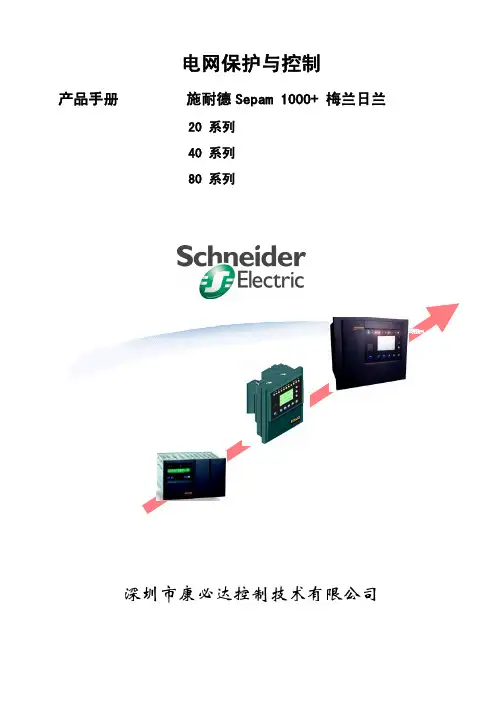
电网保护Sepam系列使用说明手册————————————————————————————————作者:————————————————————————————————日期:2施耐德SEPAM 20/40系列微机保护装置使用说明手册施耐德电气系统集成商施耐德2006年3月目录第一章 SEP AM微机保护装置的构造与功能 2 第二章面板操作说明7 第三章运行注意事项及故障显示17 第四章保护整定内容及范围19 第五章计算机软件的操作28 第六章富友嘉园10kV中心站备自投功能设置53 第七章调试、测试原则和方法59附件:富友嘉园10kV中心站保护整定清单1:进线保护整定清单2:出线保护整定清单3:分段保护整定清单4:自切保护整定清单1第一章S EPA M微机保护装置的构造与功能S e pa m20和40保护和测量单元系列产品适用于各种电压等级的工业、商业与民用等公共变电站中电力设备和配电网的保护。
保护、测量、监控等功能详见产品选型表。
S e pa m20和40系列产品是由保护和测量单元本体和逻辑输入/输出、通讯接口、温度传感器、模拟量输出等扩展模块组成。
保护和测量单元本体是保护、测量、监视及控制的中心处理部分。
它将由各个模块及信号输入所采集的数字和模拟信号加以处理,从而实现保护、测量、监视及控制的功能。
本体正面含有液晶显示面板,操作按钮及状态指示灯;背面含有电压/电流采集输入端子、四个基本的逻辑输出口和连接各种模块的接口。
逻辑输入/输出模块用于各种状态开关量的输入及控制和信号的接点输出。
按照开关量输入所相配合的辅助电源电压等级分为3种类型,分别是:ME S114 (24V~250V D C);M ES114E (110V AC/D C);M ES114F(220V AC/DC)。
其模块共有10个逻辑信号输入和4个逻辑信号输出。
2Sepam 20系列(含有MES114/MES114E/MES114F)逻辑输入/输出定义表: 名称端子号功能适用Sepam类型S20 T20 M20 B21, B22 逻辑输入I11 M1, M2 分闸位置其他(自定义使用)⑴■■■■■■■■I12 M4, M5 合闸位置其他(自定义使用)⑴■■■■■■■■I13 M7, M8 逻辑分辨, 接收闭锁整定组A/B切换其他(自定义使用) ■■■■■■■■■I14 M10, M11 外部复位外部跳闸4其他(自定义使用) ■■■■■■■■■■■■I21 K1, K2 外部跳闸1外部网络同步其他(自定义使用) ■■■■■■■■■■■■I22 K4, K6 外部跳闸2电动机重起其他(自定义使用) ■■■■■■■■■I23 K4, K7 外部跳闸3瓦斯报警转子旋转方向检测其他(自定义使用) ■■■■■■■■■■I24 K4, K8 储能结束位置温度报警其他(自定义使用) ■■■■■■■■■I25 K4, K9 禁止遥控SF6压力域值1其他(自定义使用) ■■■■■■■■I26 K4, K10 SF6压力域值2热整定切换闭锁热过载保护禁止重合闸其他(自定义使用) ■■■■■■■■■■■■■逻辑输出O1 A4, A5 跳闸其他(自定义使用)⑴■■■■■■■■O2 A7, A8 禁止合闸其他(自定义使用)⑴■■■■■■■■O3 A10, A11 逻辑闭锁输出其他(自定义使用) ■■■■■■■■O4 A13,A14,A15 继电器故障(看门狗)其他(自定义使用) ■■■■■■■■3其他(自定义使用)⑴■■■■O12 L5, L6 其他(自定义使用) ■■■■O13 L8, L9 其他(自定义使用) ■■■■O14 L11, L12 其他(自定义使用) ■■■■注: ⑴当使用断路器控制功能时,该功能不可使用。
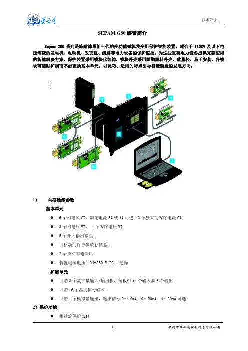
SEPAM G80装置简介Sepam G80系列是施耐德最新一代的多功能微机发变组保护智能装置。
适合于110KV及以下电压等级的发电机、电动机、发变组、线路等电力设备的保护监控,为这些重要电力设备提供完整应用的智能解决方案。
保护装置采用模块化结构,模块外壳采用阻燃塑料外壳,重量轻,易于安装,各模块可随时扩展而不必更换基本单元。
以灵巧、适用的特点引导智能装置的发展方向。
1)主要性能参数基本单元●6个相电流CT,额定电流5A或1A可选;2个独立的零序电流CT;●3个相电压VT, 1个零序电压VT;●5个开关输出接点;●可移动的保护参数存储盒;●2个独立的通信口;●装置电源电压:24-250 V DC可选择扩展单元●可带3个数字量输入/输出板,每板带14个输入和6个输出;●可带16个温度信号输入;●可带1个模拟量输出,输出信号0~10mA, 0~20mA, 4~20mA可选;2)保护功能●相过流保护(51)●接地/灵敏接地电流保护(50N/51N,50G/51G)●断路器失灵保护(50BF)●负荷不平衡、负序电流保护(46)●热过负荷保护(49RMS)●限制性接地故障(64REF)●完善可靠的差动保护(87T/87M)●方向相过流保护(67)●方向接地过流保护(67N/67NC)●方向有功过功率(32P)●方向无功过功率(32Q)●方向有功欠功率(37P)●欠电流(37)●电机启动时间监视(堵转保护)(48/51LR)●小时启动次数(66)●失磁保护(40)●失步保护(78)●超速(12)●低速(14)●低电压启动过流保护(50V/51V)●低阻抗保护(21B)●误激磁(50/27)●100%定子接地保护(64G2/27TN)●过励磁保护(24)●正序欠流(27D)●零序低电压(27R)●过压保护(59)●低压保护(27)●零序过电压(59N)●负序过压(电压相序监视47)●过频(81H)●低频(81L)●温度调节(26/63)●温度监视(38/49T)●跳闸回路监视(74)●CT/VT断线监视(60/60FL)●断路器控制(94/69)●逻辑描述功能(68)●自保持继电器(86)●重合闸(79)注:保护功能后面的数字对应该功能的美国国家标准协会ANSI代码。
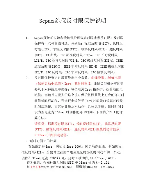
Sepam综保反时限保护说明1.Sepam保护的过流和接地保护可选定时限或者反时限,反时限保护有十六种曲线可选,分别是:标准反时限(SIT)、长时反时限(LIT)、非常反时限(VIT)、极端反时限(EIT)、超反时限(UIT)、RI曲线、IEC标准反时限SIT/A、IEC长时反时限LIT/B、IEC非常反时限VIT/B、IEC极端反时限EIT/C、IEEE适度反时限IEC/D、IEEE非常反时限IEC/E、IEEE极端反时限IEC/F、IAC反时限、IAC非常反时限、IAC极端反时限。
2.反时限保护整定时需要给出三个参数:曲线类型、域值电流(保护启动电流值)Iset、延时时间T。
曲线类型根据实际需要从十六种曲线中选择;域值电流Iset指保护开始启动的电流值,当运行电流大于这个值时保护按照曲线上对应的延时时间值延时后动作,当运行电流等于Iset时部分曲线延时较长时间后动作,而其他曲线从不动作,具体见手册。
延时时间T设为当电流为10Iset时动作的延时时间。
下面将介绍T的计算方法。
请注意,标准反时限(SIT)、长时反时限(LIT)、非常反时限(VIT)、极端反时限(EIT)、超反时限(UIT)曲线的动作值从1.2Iset开始启动动作。
3.延时时间T的计算:首先设定好Iset,例如设Iset=300A;选定动作曲线,例如选标准反时限(SIT);给出希望在某个电流处延时多长时间动作的一个点,例如在3Iset电流(900A)处,延时2秒动作,即(3Iset,t=2)。
查K值表,得知标准反时限(SIT)中3Iset处的K=2.121,则T=t/K=2/2.121=0.94295s,保留到10ms位,T=940ms图一K 值表可以在Sepam20用户手册的3/35页,在Sepam40用户手册的3/51页得到。
定值设置完毕后,可以再根据K 值表,来计算在其它某个电流处的动作延时时间,计算方法:在2Iset 即600A 处的延时时间t ’, 查K 值表,得知标准反时限(SIT)中2Iset 处的K =3.376,则t ’= K×T = 3.376×0.94 = 3.17s如果认为该时间值和预期的不一致,可适当调整定值T ,或者选择其它反时限曲线。

施耐德SEPAM 20/40系列微机保护装置使用说明手册施耐德电气系统集成商施耐德2006年3月目录第一章 SEP AM微机保护装置的构造与功能 2 第二章面板操作说明7 第三章运行注意事项及故障显示17 第四章保护整定内容及范围19 第五章计算机软件的操作28 第六章富友嘉园10kV中心站备自投功能设置53 第七章调试、测试原则和方法59附件:富友嘉园10kV中心站保护整定清单1:进线保护整定清单2:出线保护整定清单3:分段保护整定清单4:自切保护整定清单1第一章S EPA M微机保护装置的构造与功能S e pa m20和40保护和测量单元系列产品适用于各种电压等级的工业、商业与民用等公共变电站中电力设备和配电网的保护。
保护、测量、监控等功能详见产品选型表。
S e pa m20和40系列产品是由保护和测量单元本体和逻辑输入/输出、通讯接口、温度传感器、模拟量输出等扩展模块组成。
保护和测量单元本体是保护、测量、监视及控制的中心处理部分。
它将由各个模块及信号输入所采集的数字和模拟信号加以处理,从而实现保护、测量、监视及控制的功能。
本体正面含有液晶显示面板,操作按钮及状态指示灯;背面含有电压/电流采集输入端子、四个基本的逻辑输出口和连接各种模块的接口。
逻辑输入/输出模块用于各种状态开关量的输入及控制和信号的接点输出。
按照开关量输入所相配合的辅助电源电压等级分为3种类型,分别是:M E S114 (24V~250V D C);M ES114E (110V AC/DC);M ES114F(220V AC/DC)。
其模块共有10个逻辑信号输入和4个逻辑信号输出。
23⑴在Sepam S40,S41和S42中,此逻辑输入口可以在逻辑分辨、外部复位、外部跳闸、储能到位、禁止遥控、SF6压力、禁止重合闸、禁止合闸、分闸命令、合闸命令、相电压互感器熔丝熔断、剩余电压互感器熔丝熔断、外部正有功能量计数器、外部负有功能量计数器、外部正无功能量计数器及外部正无功能量计数器的功能中任选其一;⑵在Sepam T40和T42中,此逻辑输入口可以在逻辑分辨、外部复位、外部跳闸、瓦斯/气体跳闸、温度跳闸、压力跳闸、瓦斯/气体报警、温度报警、压力报警、储能到位、禁止遥控、SF6 4压力、闭锁热过载保护、热整定切换、禁止合闸、分闸命令、合闸命令、相电压互感器熔丝熔断、剩余电压互感器熔丝熔断、外部正有功能量计数器、外部负有功能量计数器、外部正无功能量计数器及外部正无功能量计数器的功能中任选其一;⑶在Sepam M41中,此逻辑输入口可以在外部复位、外部跳闸、温度跳闸、温度报警、储能到位、禁止遥控、SF6压力、闭锁热过载保护、热整定切换、电动机重起、转子旋转方向检测、闭锁欠流保护、禁止合闸、分闸命令、合闸命令、相电压互感器熔丝熔断、剩余电压互感器熔丝熔断、外部正有功能量计数器、外部负有功能量计数器、外部正无功能量计数器及外部正无功能量计数器的功能中任选其一;⑷在Sepam G40中,此逻辑输入口可以在外部复位、外部跳闸、温度跳闸、温度报警、储能到位、禁止遥控、SF6压力、闭锁热过载保护、热整定切换、禁止合闸、分闸命令、合闸命令、相电压互感器熔丝熔断、剩余电压互感器熔丝熔断、外部正有功能量计数器、外部负有功能量计数器、外部正无功能量计数器及外部正无功能量计数器的功能中任选其一;⑸当使用断路器控制功能时,该功能不可使用。
施耐德SEPAM 20/40系列微机保护装置使用说明手册施耐德电气系统集成商施耐德2006年3月目录第一章 SEP AM微机保护装置的构造与功能 2 第二章面板操作说明7 第三章运行注意事项及故障显示17 第四章保护整定内容及范围19 第五章计算机软件的操作28 第六章富友嘉园10kV中心站备自投功能设置53 第七章调试、测试原则和方法59附件:富友嘉园10kV中心站保护整定清单1:进线保护整定清单2:出线保护整定清单3:分段保护整定清单4:自切保护整定清单1第一章S EPA M微机保护装置的构造与功能S e pa m20和40保护和测量单元系列产品适用于各种电压等级的工业、商业与民用等公共变电站中电力设备和配电网的保护。
保护、测量、监控等功能详见产品选型表。
S e pa m20和40系列产品是由保护和测量单元本体和逻辑输入/输出、通讯接口、温度传感器、模拟量输出等扩展模块组成.保护和测量单元本体是保护、测量、监视及控制的中心处理部分.它将由各个模块及信号输入所采集的数字和模拟信号加以处理,从而实现保护、测量、监视及控制的功能.本体正面含有液晶显示面板,操作按钮及状态指示灯;背面含有电压/电流采集输入端子、四个基本的逻辑输出口和连接各种模块的接口.逻辑输入/输出模块用于各种状态开关量的输入及控制和信号的接点输出。
按照开关量输入所相配合的辅助电源电压等级分为3种类型,分别是:M ES114 (24V~250V DC);M ES114E (110V AC/DC);M ES114F (220V AC/D C)。
其模块共有10个逻辑信号输入和4个逻辑信号输出.23⑴在Sepam S40,S41和S42中,此逻辑输入口可以在逻辑分辨、外部复位、外部跳闸、储能到位、禁止遥控、SF6压力、禁止重合闸、禁止合闸、分闸命令、合闸命令、相电压互感器熔丝熔断、剩余电压互感器熔丝熔断、外部正有功能量计数器、外部负有功能量计数器、外部正无功能量计数器及外部正无功能量计数器的功能中任选其一;⑵在Sepam T40和T42中,此逻辑输入口可以在逻辑分辨、外部复位、外部跳闸、瓦斯/气体跳4闸、温度跳闸、压力跳闸、瓦斯/气体报警、温度报警、压力报警、储能到位、禁止遥控、SF6压力、闭锁热过载保护、热整定切换、禁止合闸、分闸命令、合闸命令、相电压互感器熔丝熔断、剩余电压互感器熔丝熔断、外部正有功能量计数器、外部负有功能量计数器、外部正无功能量计数器及外部正无功能量计数器的功能中任选其一;⑶在Sepam M41中,此逻辑输入口可以在外部复位、外部跳闸、温度跳闸、温度报警、储能到位、禁止遥控、SF6压力、闭锁热过载保护、热整定切换、电动机重起、转子旋转方向检测、闭锁欠流保护、禁止合闸、分闸命令、合闸命令、相电压互感器熔丝熔断、剩余电压互感器熔丝熔断、外部正有功能量计数器、外部负有功能量计数器、外部正无功能量计数器及外部正无功能量计数器的功能中任选其一;⑷在Sepam G40中,此逻辑输入口可以在外部复位、外部跳闸、温度跳闸、温度报警、储能到位、禁止遥控、SF6压力、闭锁热过载保护、热整定切换、禁止合闸、分闸命令、合闸命令、相电压互感器熔丝熔断、剩余电压互感器熔丝熔断、外部正有功能量计数器、外部负有功能量计数器、外部正无功能量计数器及外部正无功能量计数器的功能中任选其一;⑸当使用断路器控制功能时,该功能不可使用。

施耐德SEPAM 20/40系列微机保护装置使用说明手册施耐德2006年3月 目录第一章 SEPAM 微机保护装置的构造与功能 2 第二章 面板操作说明 7 第三章 运行注意事项及故障显示 17 第四章 保护整定内容及范围 19 第五章 计算机软件的操作 28 第六章 富友嘉园10kV 中心站备自投功能设置 53 第七章调试、测试原则和方法 59附件:富友嘉园10kV 中心站保护整定清单施耐德电气系统集成商1:进线保护整定清单2:出线保护整定清单3:分段保护整定清单4:自切保护整定清单第一章S E PA M微机保护装置的构造与功能S e pa m 20和40保护和测量单元系列产品适用于各种电压等级的工业、商业与民用等公共变电站中电力设备和配电网的保护。
保护、测量、监控等功能详见产品选型表。
S e pa m 20和40系列产品是由保护和测量单元本体和逻辑输入/输出、通讯接口、温度传感器、模拟量输出等扩展模块组成。
保护和测量单元本体是保护、测量、监视及控制的中心处理部分。
它将由各个模块及信号输入所采集的数字和模拟信号加以处理,从而实现保护、测量、监视及控制的功能。
本体正面含有液晶显示面板,操作按钮及状态指示灯;背面含有电压/电流采集输入端子、四个基本的逻辑输出口和连接各种模块的接口。
逻辑输入/输出模块用于各种状态开关量的输入及控制和信号的接点输出。
按照开关量输入所相配合的辅助电源电压等级分为3种类型,分别是:ME S114 (24V~250V DC);M ES114E (110V A C/DC);ME S114F (220V A C/D C)。
其模块共有10个逻辑信号输入和4个逻辑信号输出。
Sepam 20系列(含有MES114/MES114E/MES114F)逻辑输入/输出定义表:注: ⑴当使用断路器控制功能时,该功能不可使用。
Sepam 40系列(含有MES114/MES114E/MES114F)逻辑输入/输出定义表:注:⑴在Sepam S40,S41和S42中,此逻辑输入口可以在逻辑分辨、外部复位、外部跳闸、储能到位、禁止遥控、SF6压力、禁止重合闸、禁止合闸、分闸命令、合闸命令、相电压互感器熔丝熔断、剩余电压互感器熔丝熔断、外部正有功能量计数器、外部负有功能量计数器、外部正无功能量计数器及外部正无功能量计数器的功能中任选其一;⑵在Sepam T40和T42中,此逻辑输入口可以在逻辑分辨、外部复位、外部跳闸、瓦斯/气体跳闸、温度跳闸、压力跳闸、瓦斯/气体报警、温度报警、压力报警、储能到位、禁止遥控、SF6压力、闭锁热过载保护、热整定切换、禁止合闸、分闸命令、合闸命令、相电压互感器熔丝熔断、剩余电压互感器熔丝熔断、外部正有功能量计数器、外部负有功能量计数器、外部正无功能量计数器及外部正无功能量计数器的功能中任选其一;⑶在Sepam M41中,此逻辑输入口可以在外部复位、外部跳闸、温度跳闸、温度报警、储能到位、禁止遥控、SF6压力、闭锁热过载保护、热整定切换、电动机重起、转子旋转方向检测、闭锁欠流保护、禁止合闸、分闸命令、合闸命令、相电压互感器熔丝熔断、剩余电压互感器熔丝熔断、外部正有功能量计数器、外部负有功能量计数器、外部正无功能量计数器及外部正无功能量计数器的功能中任选其一;⑷在Sepam G40中,此逻辑输入口可以在外部复位、外部跳闸、温度跳闸、温度报警、储能到位、禁止遥控、SF6压力、闭锁热过载保护、热整定切换、禁止合闸、分闸命令、合闸命令、相电压互感器熔丝熔断、剩余电压互感器熔丝熔断、外部正有功能量计数器、外部负有功能量计数器、外部正无功能量计数器及外部正无功能量计数器的功能中任选其一;⑸当使用断路器控制功能时,该功能不可使用。

施耐德继电保护装置的使用及调试我司所用继电保护装置有施耐德、西门子、阿海珐等公司提供的产品。
RVPS所用的保护装置大部分都是施耐德Sepam M20和Sepam S20两种型号。
Sepam M20用于高压马达的继电保护,Sepam S20用于变电站的继电保护。
这两种型号除了内部某些功能的不同外,其外形大体一致(如下图一)。
图一施耐德继电保护装置的额定电压为220V AC,上图所示,当继电保护装置安装完成并送电时,‘10’指示灯会常亮,表示装置已经送电开始工作;同时‘11’将会闪烁红灯5s左右,表示继电保护装置内部系统正在自检;‘2’显示并输入Sepam的通用整定值,这些整定值定义了被保护设备的特性,以及不同的可选模块;‘3’可显示、整定、以及允许/禁止保护功能;‘4’‘5’键使得光标上下移动,方便参数各个功能的设置;‘6’为确认保护整定,参数整定和密码;当设置装置内部参数时,按‘1’,显示为下图二:图二本司保护装置的密码为‘0000’或‘9999’.当输入密码后,按‘6’键确认,即可进入参数设置页面,下图三所示。
图三参数设置有两套分别为‘A’和‘B’,当我们执行‘A’时,所有在‘A’系统设置并且选择‘开’的参数功能将投入使用,如下图四所示‘1A’,‘开’、‘关’;‘SIT’表示此参数功能的动作曲线为‘定时限’,此外还有‘VIT’反时限曲线、‘EIT’极反时限、‘UIT’超反时限等曲线选择。
图四在本司马达设置中,‘50/51 1A’代表的功能为‘过流’;‘50/51 2A’代表的功能是‘过流速断’;‘50N/51N 1A’代表的功能为‘零序’;‘50N/51N 2A’代表的功能为‘零序速断’;‘46’代表的功能为‘负序’;‘49RMS’代表的功能为‘过载’;‘37’代表的功能为‘相欠电流’;‘48/51LR’代表的功能为‘启动超时,转子堵转’;‘27’代表的功能为‘欠压’;此外还有‘温度监视’等功能。
I O 0000002750.02Modicon M580 SafetyStandards and Certifications(Original Document)12/2018The information provided in this documentation contains general descriptions and/or technical characteristics of the performance of the products contained herein. This documentation is not intended as a substitute for and is not to be used for determining suitability or reliability of these products for specific user applications. It is the duty of any such user or integrator to perform the appropriate and complete risk analysis, evaluation and testing of the products with respect to the relevant specific application or use thereof. Neither Schneider Electric nor any of its affiliates or subsidiaries shall be responsible or liable for misuse of the information contained herein. If you have any suggestions for improvements or amendments or have found errors in this publication, please notify us.You agree not to reproduce, other than for your own personal, noncommercial use, all or part of this document on any medium whatsoever without permission of Schneider Electric, given in writing. You also agree not to establish any hypertext links to this document or its content. Schneider Electric does not grant any right or license for the personal and noncommercial use of the document or its content, except for a non-exclusive license to consult it on an "as is" basis, at your own risk. All other rights are reserved.All pertinent state, regional, and local safety regulations must be observed when installing and using this product. For reasons of safety and to help ensure compliance with documented system data, only the manufacturer should perform repairs to components.When devices are used for applications with technical safety requirements, the relevant instructions must be followed.Failure to use Schneider Electric software or approved software with our hardware products may result in injury, harm, or improper operating results.Failure to observe this information can result in injury or equipment damage.© 2018 Schneider Electric. All rights reserved.Table of ContentsSafety Information . . . . . . . . . . . . . . . . . . . . . . . . . . . . . . . . . . . . . . . . . . . . . . . . . . . . .5 About the Book . . . . . . . . . . . . . . . . . . . . . . . . . . . . . . . . . . . . . . . . . . . . . . . . . . . . . . .7 Platforms Conformity. . . . . . . . . . . . . . . . . . . . . . . . . . . . . . . . . . . . . . . . . . . . . . . . . . .9 Certificates and Declarations. . . . . . . . . . . . . . . . . . . . . . . . . . . . . . . . . . . . . . . . . . . . .9 Installation General Rules . . . . . . . . . . . . . . . . . . . . . . . . . . . . . . . . . . . . . . . . . . . . . . .10 Operating and Storage Conditions . . . . . . . . . . . . . . . . . . . . . . . . . . . . . . . . . . . . . . . .10 Environment Test Compliance Levels. . . . . . . . . . . . . . . . . . . . . . . . . . . . . . . . . . . . . .12Safety InformationImportant InformationNOTICERead these instructions carefully, and look at the equipment to become familiar with the device before trying to install, operate, service, or maintain it. The following special messages may appear throughout this documentation or on the equipment to warn of potential hazards or to call attention to information that clarifies or simplifies a procedure.PLEASE NOTEElectrical equipment should be installed, operated, serviced, and maintained only by qualifiedpersonnel. No responsibility is assumed by Schneider Electric for any consequences arising out of the use of this material.A qualified person is one who has skills and knowledge related to the construction and operationof electrical equipment and its installation, and has received safety training to recognize and avoid the hazards involved.About the BookAt a GlanceDocument ScopeThis document presents the Standards and Certifications for the M580 Safety range.For any information related to functional safety refer to the Modicon M580, Safety Manual, and Modicon M580, Safety System Planning Guide.Validity NoteThis document is valid for EcoStruxure™Control Expert14.0 or later.Related DocumentsTitle of Documentation Reference NumberModicon M580, Safety Manual QGH46982(English),QGH46983(French),QGH46984(German),QGH46985(Italian),QGH46986(Spanish),QGH46987(Chinese) Modicon M580, Safety System Planning Guide QGH60283(English),QGH60284(French),QGH60285(German),QGH60286(Spanish),QGH60287(Italian),QGH60288(Chinese)Modicon X80 Racks and Power Supplies, Hardware, Reference Manual EIO0000002626(English), EIO0000002627(French), EIO0000002628(German), EIO0000002630(Italian), EIO0000002629(Spanish), EIO0000002631(Chinese)Grounding and Electromagnetic Compatibility of PLC Systems, Basic Principles and Measures, User Manual 33002439(English), 33002440(French), 33002441(German), 33003702(Italian), 33002442(Spanish), 33003703(Chinese)You can download these technical publications and other technical information from our website at https:///en/downloadProduct Related InformationWARNINGUNINTENDED EQUIPMENT OPERATIONThe application of this product requires expertise in the design and programming of controlsystems. Only persons with such expertise are allowed to program, install, alter, and apply this product.Follow all local and national safety codes and standards.Failure to follow these instructions can result in death, serious injury, or equipment damage.Platforms ConformityThe Modicon M580 Safety platform has been developed to comply with the principal national and●❍Machinery: 2006/42/EC❍Electromagnetic Compatibility: 2014/30/EU●Requirements specific to programmable controllers relative to PLC standard IEC/EN 61131-2and electrical safety standards IEC/EN/UL/CSA 61010-2-201●Requirements specific to power utility automation systems: IEC/EN 61000-6-5, IEC/EN 61850-3●Merchant navy requirements of the major international agencies unified in organization(International Association of Classification Societies) IACS E10 rules: BV, DNV-GL, ABS, LR,RINA, KRS, CCS●Ex areas:❍For USA and Canada: Hazardous location class I, division 2, groups A,B,C, and D❍For other countries: CE ATEX (2014/34/EU) or IECEx in Zone 2 (gases) and Zone 22 (dust)●Country specific passport:❍RMC, EAC, KCCertificates and DeclarationsProduct certificates and declarations are available for download on Schneider Electric website:Step Action1Connect to global website.2Click PRODUCTS → PLC, PAC and Dedicated Controllers.3Click the product range for which certificates or declarations are needed (for example Modicon M580 - ePac Controller, or Modicon X80 I/Os ...).4In the Documents & Downloads tab, click See More Documents.A new page with a menu on the left side appears.5In the left side menu, under Document Type Group category, click the type of document you are looking for (Certificate, Marine certificate, Declaration of conformity, ... ).The page content is refreshed and presents the available documents for the product range.If the type of document is not visible in the left side menu, under Document Type Group category, clickthe + button at the right side of More options... to display more document types.6Select the document for downloadNOTE: In case of Schneider Electric website evolution, the menu names and paths may slightly differ.Installation General RulesThe Modicon M580 Safety platform is intended for use in a pollution degree 2 industrialenvironment, in over-voltage Category II applications (as defined in IEC 60664-1), at altitude up to 2000m without derating and in low-voltage installations, where the main power branch is protected on both wires by devices such as fuses or circuit breakers limiting the current to 15A for North America and 16A for the rest of the world.Modicon platforms are open-type equipment as defined in IEC 61010-2-201. Mount these modules in an enclosure that is appropriate for the specific environmental conditions. Design the installation to prevent personal injury from exposure to live parts. Use an enclosure with flame-retardant properties to prevent or minimize the spread of fire.You can install these modules without enclosure in controlled-access offices and labs that do not exceed pollution degree 2 (control rooms with no dust-producing machines or activity). Pollution degree 2 does not account for more severe environmental conditions, like air pollution by dust, smoke, corrosive or radioactive particles, vapors or salts, attack by fungi, insects, and so on.Operating and Storage ConditionsCharacteristicsAltitudeThese modules are designed to operate with full characteristics (current, power) at altitudes up to 2000m.Characteristics Modicon M580 Safety Platform Ambient temperature (1)Operation -25...+60°C (-13...+140°F)Storage -40...+ 85 °C (-40...+185 °F)Relative humidity (without condensation)Cyclical humidity +5...+95% up to 55°C (+131 °F)Continuous humidity +5...+93% up to 55°C (+131°F)AltitudeOperation0…2000mFor greater altitude, refer to chapter Altitude (see page 10).(1) For non-vented equipment that is mounted in a cabinet and cooled by natural air convection, the ambienttemperature is the air temperature at a point not more than 50mm and not less than 25mm away from the equipment, on a horizontal plane located at the vertical mid-point below the equipment.The Control Expert software defines the maximum number of modules that you can use with a single power supply at those altitudes. For more detailed information, refer to chapter PowerConsumption Breakdown (see Modicon X80, Racks and Power Supplies, Hardware Reference Manual).An additional derating applies to modules that operate above 2000m altitude:●On the maximum ambient temperature or on the maximum power consumption ●On the dielectric strengthThese deratings compensate for the reduced capacity of heat transfer that owes to the relatively lower air density, pressure, and temperature at higher altitudes.Depending on the maximum operating ambient temperature of the equipment, you can decide:●Either to maintain the output capabilities of the modules and reduce the maximum ambient temperature or;●Reduce the output capabilities of the modules that allows to keep the maximum ambient temperature.Conservation of Outputs CapabilitiesThe module characteristics such as current and power remain unchanged if the maximum ambient temperature does not exceed these values:NOTE: This solution is suitable for power supplies, and modules that have only internal dissipation such as CPUs, communication modules, and so on.Conservation of Maximum Ambient TemperatureThe modules can be installed at maximum ambient temperature +60°C (140°F) if the usable output power and current are reduced:Altitude Maximum operating ambient temperature0...2000m +60°C (+140°F)3000m +54°C (+129.2°F)4000m +48°C (+118.4°F)5000m+42°C (+107.6°F)NOTE: Values for intermediate altitudes may be derived by linear interpolation.Altitude Usable output power Usable output current 0...2000mP 2000mI 2000mP 2000m : This is the maximum available power of a power supply on 3V3_BAC , 24V_BAC , or 24V_SENSORSat 2000m.I 2000m : This is the output current.NOTE: Values for intermediate altitudes may be derived by linear interpolation.After determining the maximum usable current delivered by the power supply with the above deratings, check with Control Expert that the consumption of the modules into the rack is compatible with the new calculated values.NOTE: For digital output modules, apply the calculated derating to the output current capabilities and adapt the corresponding loads.Reduced Dielectric StrengthAn increase in altitude reduces the dielectric strength characteristics. This table shows the degradation of isolation at specific altitudes:We highly recommend that you select the double-isolation BMXCPS4002S module as the main power supply 230Vac.Environment Test Compliance LevelsOverviewStandards and levels are provided for these tests:●Immunity to low frequency interference (see page 13)●Immunity to high frequency interference(see page 14)●Electromagnetic emissions (see page 15)●page 16)●Withstand to climatic variations (Power OFF) (see page 17)3000m P 2000m x 0.9I 2000m x 0.954000m P 2000m x 0.8I 2000m x 0.895000mP 2000m x 0.7I 2000m x 0.84Altitude Usable output power Usable output current P 2000m : This is the maximum available power of a power supply on 3V3_BAC , 24V_BAC , or 24V_SENSORSat 2000m.I 2000m : This is the output current.NOTE: Values for intermediate altitudes may be derived by linear interpolation.Altitude Dielectric strength loss0...2000m Dielec 2000m = Values given in module characteristics 3000m Dielec 2000m - 150V 4000m Dielec 2000m - 300V 5000mDielec 2000m - 450VNOTE: Values for intermediate altitudes may be derived by linear interpolation.●Immunity to mechanical constraints (Power ON) (see page17)●Withstand to mechanical constraints (Power ON) (see page18)●Equipment and personnel safety (see page18)NOTE:61131-2 standards.NOTE: Install, wire, and maintain the devices in accordance with the instructions in the Grounding and Electromagnetic Compatibility of PLC Systems, Basic Principles and Measures, User Manual.Name of test Standards LevelsVoltage and frequency variations IEC/EN 61131-2; IEC/EN 61000-6-2;IEC 61000-4-110.85...1.10 Un –0.94...1.04 Fn; 4 stepst=30 minIACS E10; IEC 61000-4-110.80 Un...0.90 Fn; 1.20 Un...1.10 Fn;t=1.5s/5sDirect voltage variations IEC/EN 61131-2; IEC 61000-4-29;IACS E10 (PLC not connected tocharging battery)0.85...1.2 Un + ripple: 5% peak; 2 stepst=30minThird harmonic IEC/EN 61131-2H3 (10% Un), 0°/180°; 2 steps t=5minImmunity to conducted low frequency (only IACS)IACS E10For AC:●H2…H15(10%Un),H15…H100(10%...1%Un),H100…H200(1%Un)For DC:●H100…H200(1%Un)Voltage interruptions IEC/EN 61131-2; IEC/EN 61000-6-2;IEC 61000-4-11; IEC 61000-4-29;IACS E10For functional safety (DS criteria):IEC61000-6-7; IEC 61326-3-1Power supply immunity:●10 ms for AC and DC PS2 (20msDS criteria)●Check operating mode for longerinterruptions up to 5s, 85%UnFor IACS, 3 times 30s in 5mn, 85%UnIEC/EN 61131-2; IEC/EN 61000-6-2; IEC 61000-4-11For AC PS2:●20%Un, t0: ½ period ●40%Un, cycle: 10/12●70%Un, cycle: 25/30●0%Un, cycle: 250/300Where:PS1 applies to PLC supplied by batteryPS2 applies to PLC energized from AC or DC supplies Un nominal voltageFn nominal frequencyUdl detection level when poweredNOTE: These tests are performed without an enclosure and with devices fixed on a metal grid and wired as per the recommendations in the Grounding and Electromagnetic Compatibility of PLC Systems, Basic Principles and Measures, User Manual .Voltage shut-down and start-up IEC/EN 61131-2●Un…0…Un; t =Un/60 s ●Umin…0…Umin; t =Umin/5 s ●Umin…0.9 Udl…Umin; t =Umin/60sMagnetic fieldIEC/EN 61131-2; IEC 61000-4-8 (for MV power stations: IEC 61000-6-5; IEC 61850-3)For functional safety (DS criteria): IEC 61000-6-7; IEC 61326-3-1Power frequency: 50/60Hz, 100A/m continuous...1000A/m; t = 3 s; 3axes IEC 61000-4-10Oscillatory: 100 kHz...1MHz, 100A/m; t =9s; 3axesConducted common mode disturbances range 0Hz…150kHzIEC 61000-4-16 (for MV power stations: IEC 61000-6-5; IEC 61850-3)For functional safety (DS criteria): IEC 61000-6-7; IEC 61326-3-1For AC: 10VFor DC: 10V cont. or 100V,t =1s Name of test Standards LevelsWhere:PS1 applies to PLC supplied by batteryPS2 applies to PLC energized from AC or DC supplies Un nominal voltage Fn nominal frequencyUdl detection level when poweredName of test StandardsLevelsElectrostatic dischargesIEC/EN 61131-2; IEC/EN 61000-6-2; IEC 61000-4-2; IACS E10For functional safety (DS criteria): IEC 61000-6-7; IEC 61326-3-16kV contact; 8kV air; 6kV indirect contactRadiated radio frequencyelectromagnetic fieldIEC/EN 61131-2; IEC/EN 61000-6-2; IEC 61000-4-3; IACS E10For functional safety (DS criteria): IEC 61000-6-7; IEC 61326-3-180MHz...1GHz: 10/15V/m (20V/m DS criteria)1.4GHz...2GHz: 3V/m (10V/m DS criteria)2GHz...6GHz: 3V/mSinus amplitude modulated 80%,1kHz + internal clock frequenciesNOTE: Install, wire, and maintain the devices in accordance with the instructions in the Grounding and Electromagnetic Compatibility of PLC Systems, Basic Principles and Measures, User Manual .Electrical fast transient burstsIEC/EN 61131-2; IEC/EN 61000-6-2; IEC 61000-4-4; IACS E10For functional safety (DS criteria): IEC 61000-6-7; IEC 61326-3-1For AC or DC main supplies:●2kV in common mode/2kV in wire mode For AC or DC auxiliary supplies, AC unshielded I/O:●2kV in common mode For analog, DC unshielded I/O, communication and shielded lines:●1kV in common modeSurgeIEC/EN 61131-2; IEC/EN 61000-6-2; IEC 61000-4-5; IACS E10For functional safety (DS criteria): IEC 61000-6-7; IEC 61326-3-1For AC or DC main and auxiliary supplies, AC unshielded I/O:●2kV in common mode/1kV indifferential mode (4kV DS criteria with external protection)For analog, DC unshielded I/O:●2kV in common mode/2kV in differential mode For communication and shielded lines:●1kV in common mode (3kV DS criteria)Conducteddisturbances induced by radiatedelectromagnetic fields IEC/EN 61131-2; IEC/EN 61000-6-2; IEC 61000-4-6; IACS E10For functional safety (DS criteria): IEC 61000-6-7; IEC 61326-3-110V; 0.15MHz...80MHz (20V DS criteria)Sinus amplitude 80%, 1kHz + spot frequenciesDamped oscillatory waveIEC/EN 61131-2; IEC 61000-4-18; IACS E10For AC or DC main supplies and AC auxiliary supplies, AC unshielded I/O:● 2.5kV in common mode/1kV in differential mode For DC auxiliary supplies, analog, DC unshielded I/O:●1kV in common mode/0.5kV in differential mode For communication and shielded lines:●0.5kV in common modeName of test StandardsLevelsImmunity to Climatic Variations (Power ON) TestsNOTE: Install, wire, and maintain the devices in accordance with the instructions in the Grounding and Electromagnetic Compatibility of PLC Systems, Basic Principles and Measures, User Manual .Name of test StandardsLevelsConducted emissionIEC/EN 61131-2; IEC/EN 61000-6-4; CISPR 11 and 22, Class A, Group 1 (FCC part 15 compliance)150…500kHz: quasi-peak 79dB (μV/m); average 66dB (μV/m)500kHz…30MHz: quasi-peak73dB (μV/m); average 60dB (μV/m)IACS E10●AC or DC power (general powerdistribution zone): 10kHz…150kHz: quasi-peak 120...69dB (μV/m); 150kHz…0.5MHz: quasi-peak79dB (μV/m) 0.5…30MHz: quasi-peak 73dB (μV/m)●AC or DC power (bridge and deck zone for evaluation): 10kHz…150kHz: quasi-peak 96…50dB (μV/m) 150kHz…0.35MHz: quasi-peak 60…50dB (μV/m) 0.35…30MHz: quasi-peak 50dB (μV/m)Radiated emissionIEC/EN 61131-2; IEC/EN 61000-6-4; CISPR 11 and 22, Class A, Group 1 (FCC part 15 compliance)30MHz...230MHz: quasi-peak 40dB (µV/m) (at 10m);230MHz...1GHz: quasi-peak 47dB (µV/m) (at 10m);1...3GHz: quasi-peak 76dB (µV/m) (at 3m);3...6GHz: quasi-peak 80dB (µV/m) (at 3m);IACS E10For general power distribution zone:●0.15MHz … 30MHz: quasi-peak 80…50dB (μV/m) (at 3m)●30...100MHz: quasi-peak 60…54dB (μV/m) (at 3 m)●100MHz...2GHz: quasi-peak 54dB (μV/m) (at 3m)●156…165MHz: quasi-peak 24dB (μV/m) (at 3 m)Name of test StandardsLevelsDry heatIEC 60068-2-2 (Bb and Bd)60°C (+140°F), t =16hrs IACS E1060°C (+140°F), t =16hrs +70°C (+158°F),t =2hrsWithstand to Climatic Variations (Power OFF) TestsNOTE: The devices must be installed, wired and maintained in accordance with the instructions provided in the Grounding and Electromagnetic Compatibility of PLC Systems, Basic Principles and Measures, User Manual .Immunity to Mechanical Constraints (Power ON) TestsNOTE: Install, wire, and maintain the devices in accordance with the instructions in the Grounding and Electromagnetic Compatibility of PLC Systems, Basic Principles and Measures, User Manual .ColdIEC 60068-2-1 (Ab and Ad); IACS E10-25…0°C (–13...32°F), t =16hrs + poweron at –25°C Damp heat, steady state (continuous humidity)IEC 60068-2-78 (Cab); IACS E1055°C (+131°F), 93% relative humidity, t =96hrs (for ruggedized range: 60°C (+140°F))Damp heat, cyclic (cyclical humidity)IEC 60068-2-30 (Db); IACS E1025…55°C (77...131°F), 93…95% relative humidity, 2 cycles t =12hrs +12hrs Change of temperatureIEC 60068-2-14 (Nb)0 …60°C (32...140°F), 5 cyclest =6hrs +6hrs (for ruggedized range: -25…70°C (77...158°F))Name of test Standards LevelsName of test StandardsLevelsDry heat IEC/EN 61131-2; IEC 60068-2-2 (Bb and Bd); IEC/EN 6094585°C (185°F), t =96 hrs ColdIEC/EN 61131-2; IEC 60068-2-1 (Ab and Ad); IACS E10–40°C (–40°F), t =96hrsDamp heat, cyclic (cyclical humidity)IEC/EN 61131-2; IEC 60068-2-30 (Db)25…55°C (77...131°F), 93…95% relativehumidity, 2 cycles t =12hrs +12hrsChange of temperature (thermal shocks)IEC/EN 61131-2; IEC 60068-2-14 (Na)–40...85°C (–40...185°F), 5 cycles t =3hrs +3hrsWithstand to Mechanical Constraints (Power OFF) TestsEquipment and Personnel Safety TestsNOTE: Install, wire, and maintain the devices in accordance with the instructions in the Grounding and Electromagnetic Compatibility of PLC Systems, Basic Principles and Measures, User Manual .Name of test StandardsLevelsSinusoidal vibrationsIEC/EN 61131-2; IEC 60068-2-6 (Fc)Basic IEC/EN 61131-2:● 5...150Hz, ± 3.5mm amplitude (5…8.4Hz), 1g (8.4…150Hz)Enhanced profile:● 5...150Hz, ± 10.4mm amplitude (5….8.4Hz), 3g (8.4….150Hz)For basic and specific: endurance:●10 sweep cycles for each axisIEC 60870-2-2; IEC 60068-2-6 (Class Cm) (for telecontrol equipment and system) 3...8.4Hz, 7mm amplitude, 8.4...500Hz, 2gEndurance: 10 sweep cycles for each axis IACS E103...100Hz, 1mm amplitude (3…13.2Hz), 0.7g (13.2 …100Hz)Endurance at each resonance frequency: 90 min for each axis, amplification coefficient <10IEC 60068-2-6Sismic analysis: 3...35Hz, 22.5mm amplitude (3…8.1Hz), 6g (8.1…35Hz)Shocks IEC/EN 61131-2; IEC 60068-2-27 (Ea)15g, 11ms; 3 shocks/direction/axis Free fall during operationIEC/EN 61131-2; IEC 60068-2-32 (Ed Method 1)1m (3.28ft), 2 falls Name of testStandardsLevelsRandom free fall with packaging IEC/EN 61131-2; IEC 60068-2-32 (Method 1)1m (3.28ft), 5 fallsFlat free fall IEC/EN 61131-2; IEC 60068-2-32 (Ed Method 1)10cm (0.33ft), 2 fallsControlled free fall IEC/EN 61131-2; IEC 60068-2-31 (Ec)30° or 10cm (0.33ft), 2 falls Plugging/UnpluggingIEC/EN 61131-2For modules and connectors: Operations: 50 for permanent connections, 500 for non-permanent connectionsName of test Standards LevelsDielectric strength and insulation resistance IEC/EN 61131-2; IEC 61010-2-201;UL; CSADielectric: Min. 2Un+1000Vac (seedetails in Modicon M580, Safety SystemPlanning Guide); t=1minInsulation: Un≤50V: 10MΩ,50V≤Un≤250V: 100MΩContinuity of earth IEC/EN 61131-2; IEC 61010-2-201;UL; CSA30A, R≤0,1Ω; t=2minLeakage current IEC/EN 61131-2; IEC 61010-2-201;UL; CSA < 0.5mA in normal condition< 3.5mA in single fault conditionProtection offered by enclosures IEC/EN 61131-2; IEC61010-2-201;IP20 and protection against standardizedpinsOverload IEC/EN 61131-2; IEC 61010-2-201;UL; CSA50 cycles, Un, 1.5In; t=1s ON+9s OFFEndurance IEC/EN 61131-2; IEC 61010-2-201;UL; CSAIn, Un; 6000cycles, 1s ON+9s OFFTemperature rise IEC/EN 61131-2; UL; CSA; ATEX;IECExAmbient temperature 60°C (140°F)。
HANDHELD TERMINALQuick start guidePM80DeviceStylus pen with Tether AC/DC Adaptor (AC plug)Battery Wrist Strap LCD protection filmVolume3. Hold the ribbon and lift upward to remove battery4. Insert battery cover,top first and press it in the order named on the picture. Then press down on battery at the center again.•Please read this manual before using the device and follow the instructions correctly.•Some content may differ from your device depending on the device’s software version.Standard accessoryCharging the battery 1. Insert plug on AC/DC Adaptor and connect to electric socket to charge.2. LED indicator on upper left of device shows red light while charging and it turns to green light when the device is fully charged.<Caution>•Use only items provided in your purchase for charging.•You can also charge the device with optional accessory, cradle.5V 2A AC/DC AdaptorWrist StrapStylus pen with Tether Battery (3000mAh)plugLCDprotection filmOptional accessarySSC(Single Slot Cradle)4SC(4 Slot Cradle)4SBC(4 Slot Battery Charger)PUSHI/O USB Sync cableExtended Battery(4000mA)Point the scanning beam at the center of barcode and keep scanning angle vertical to it.Scanning range varies according to bar code sizesokeep minimum distance forsmall barcode and further distance for bigger one.Scanning1. Execute Demos application on home screen.2. Tab ScanDemo toopen.3. Press both scan keys at once or any of scan key on the device to scan barcode.4. Scanned barcode data will show on screen as on the picture left.Testing barcode scannerRebootPress and hold power key for 3 seconds and select Reboot on options to reboot the device.Factory resetFollow the process by tapping next button to complete factory reset.<Caution>•Back up all data -personal, application settings,account information and etc. before performing factory reset as it causes all data delete.OfflineTel:02-3397-7870Fax:02-3397-7872Address: B-9F Kabul Great Valley, 32, Digital-ro 9-gil,Geumcheon-gu, Seoul, Korea 08512OnlineWebsite:http://www.pointmobile.co.kr/E-mail:*********************.krUser guides supports detailed information on safety & regulations of device and accessories.Due to the possibility of electric wave interference by device, no support on life safety.Technical support & A/SUser guidesCertificationEquipment name: Wireless data communication system device (Wireless Access System device withWireless LAN)Model: PM80Trade name of certified: POINT MOBILE CO.LTD Manufacturer/ Country of origin: POINT MOBILE CO.LTD/ ChinaProduction date: 2015.12.XXCertification No.: MSIP-CMM-PM1-PM80WConnecting USB data Sync cableConnect to PC and transfer data in Micro SD card/ device storage with I/O USB data Sync cable.Connecting –connect USB cable to USB port of PC and I/O connector.–Tab media device connection on notification panelof status bar.–Select file transfer on pop up window.Disconnecting –Tab to show notification panel and select media device connection.–Select media device (MTP) and disable theconnection.Connecting to PC Settings -> back up and reset -> Factory reset -> Reset phoneLi-ion battery follows varied regulations in each region/ country. Accordingly, recycle or disuse li-ion battery properly. Do not leave or store it in fire or heat it or disassemble or short circuit it.Prevent plug and consent from dust and dirt to keep them clean. Improper storing or misuse may cause fire, electric shock, etc.Do not allow any strong pressure or impact on the touch screen.Do not touch any interior liquid fromLCD panel breakage that may cause skin e only approved AC/DC power adaptor provided with device or from distributor.Disapproved products may cause unexpected problems as fire, electric shock, etc.Disapproved modification or repair is not guaranteed. Inquire to distributor for any troubleshooting.HANDY TERMINALQuick start guidePM80•For more details of product information and user guide, please refer to our website (www.pointmobile.co.kr )。