BELIMO 蝶阀安装说明书
- 格式:pdf
- 大小:450.81 KB
- 文档页数:9

阀门安装与使用手册德国依博罗阀门有限公司Z011, Z014, F012, M015-A 系列目 录1 注意事项 应用领域 安装 操作 拆卸 封底页:阀门安装图解说明 6 维护 维修 故障诊断与处理 双阀杆结构 单阀杆结构2738495101 注意事项本操作手册用来帮助用户正确安装和维护 EBRO 蝶阀,确保阀门的安全无故障运行。
安装前,请不要将阀门从包装中取出。
阀门必须在干燥无尘环境中避光存放。
如果能正确存放阀门,则无须额外保存措施。
阀门的安装、拆卸和维护工作必须由接受过培训的专业人员担任。
拆卸阀门前,首先必须使阀门停止运行并与系统隔离,而且确保阀门内无压力。
阀门的停止运行操作要由专人控制(如切断电源、拆卸驱动联接装置和安全防护措施) 。
根据用户特殊要求设计的阀门仅可在设计指定条件下使用。
2 应用范围EBRO 依博罗蝶阀可担任系统关键部位的隔离和调节功能,广泛应用于几乎所有工业领 域的管线中,适用的介质有液体,气体和粒状物等。
主要应用领域有: - 化学和石化工业 - 海洋工程 - 供气系统 - 食品工业 - 废水处理及给排水工程 - 冷库及暖通空调系统 - 电厂及供热厂3 安装EBRO 依博罗蝶阀适用于多种法兰安装标准,如 DIN2501 (PN6/10/16), ANSI B 16.5 Class 150, MSS SP44 Class 150 等标准设计的法兰。
请按相应标准定制法兰,具体情况欢迎垂询。
阀门密封等级为双向气泡级零泄漏,可安装在任何选定位置。
EBRO 依博罗蝶阀阀座密封圈还起着法兰密封垫片作用,无须另外附加额外垫片。
· 2严禁将装有阀门的法兰直接与管线焊接,阀座密封圈会由于过热或烧烤而损坏。
我们推荐的方法为:先用四个法兰螺栓将阀门定位在法兰间,然后通过点焊将法兰与管 线固定在一起。
然后再卸下阀门,将法兰与管线完全密封焊接在一起。
待焊接处完全冷却后,安装阀门,此时,阀门正好轻轻夹在两法兰间。
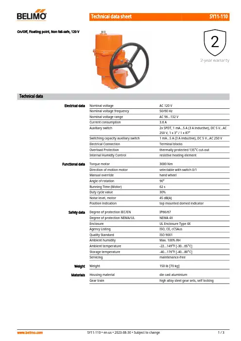
SY11-110On/Off, Floating point, Non fail-safe, 120 VTechnical dataElectrical data Nominal voltage AC 120 VNominal voltage frequency50/60 HzNominal voltage range AC 96...132 VCurrent consumption 3.6 AAuxiliary switch2x SPDT, 1 mA...5 A (3 A inductive), DC 5 V...AC250 V, 1 x 3° / 1 x 87°Switching capacity auxiliary switch 1 mA...5 A (3 A inductive), DC 5 V...AC 250 VElectrical Connection Terminal blocksOverload Protection thermally protected 135°C cut-outInternal Humidty Control resistive heating elementFunctional data Torque motor3000 NmDirection of motion motor selectable with switch 0/1Manual override hand wheelAngle of rotation90°Running Time (Motor)62 sDuty cycle value30%Noise level, motor45 dB(A)Position indication top mounted domed indicatorSafety data Degree of protection IEC/EN IP66/67Degree of protection NEMA/UL NEMA 4XEnclosure UL Enclosure Type 4XAgency Listing ISO, CE, cCSAusQuality Standard ISO 9001Ambient humidity Max. 100% RHAmbient temperature-22...149°F [-30...65°C]Storage temperature-40...176°F [-40...80°C]Servicing maintenance-freeWeight Weight150 lb [70 kg]Materials Housing material die cast aluminiumGear train high alloy steel gear sets, self lockingSY11-110ApplicationProduct featuresSY Series actuators are fractional horsepower devices, and utilize full-wave power supplies. Observe wire sizing and transformer sizing requirements. Proportional models CANNOT be connected to Belimo direct coupled (AF, AM, GM…etc) actuator power supplies or any type of half-wave device. You MUST use a separate, dedicated transformer or power supply to power the SY actuator. Please do not connect other automation equipment to the dedicated SY supply source. You MUST use four wires (plus a ground) to control a proportional control SY actuator (See SY Wiring Section).AccessoriesElectrical accessoriesDescriptionTypeLocal electric disconnect for SY4...12 series actuator, AC 120 V, on/off HOA-120VBattery backup system for SY7...12 series actuator, AC 120 V, on/offEXT-NSV-B05-120Electrical installationINSTALLATION NOTESDo not change sensitivity or dip switch setting with power applied.Power supply Common/Neutral and Control Signal "-"wiring to a common is prohibited.Terminals 4 and 6 need to be wired separately.Isolation relays must be used in parallel connection of multiple actuators using a commoncontrol signal inputs. The relays should be DPDT.Isolation relays are required in parallel applications. The reason parallel applications needisolation relays is that the motor uses two sets of windings, one for each direction. When one is energized to turn the actuator in a specific direction a voltage is generated in the other due to the magnetic field created from the first. It’s called back EMF. This is not an issue with one actuator because the voltage generated in the second winding isn’t connected to anything so there is no flow. On parallel applications without isolation, this EMF voltage energizes the winding it is connected to on the other actuators in the system, the actuators are tying to turn in both directions at once. The EMF voltage is always less than the supply voltage due to the resistance of the windings, so while the actuator still turns in the commanded direction, thedrag from the other reduces the torque output and causes overheating.Warning! Live electrical components!During installation, testing, servicing and troubleshooting of this product, it may be necessary to work with live electrical components. Have a qualified licensed electrician or other individual who has been properly trained in handling live electrical components perform these tasks. Failure to follow all electrical safety precautions when exposed to live electrical components could result in death or serious injury.SY11-110Wiring diagramsAC/DC 110/120 or 220/230VAC 110/120 or 220/230 VElectrical installation。

产品技术资料Belimo China蝶阀第3.0版目 录目录2蝶阀和执行器蝶阀与执行器概览及应用3BU6.. 系列电动蝶阀BU6.. 蝶阀概览5BU6..蝶阀选型7BU6.. 单夹与对夹式蝶阀9BU6.. 蝶阀尺寸规格10通用角行程执行器SR..-5 通用角行程执行器11GR..-5/-7 通用角行程执行器14DR..-7通用角行程执行器17机械式自复位角行程执行器SRFA..-5 机械式自复位角行程执行器20电子式自复位角行程执行器GRK..-5/-7 电子式自复位角行程执行器23大扭矩多功能执行器SY.. 大扭矩多功能执行器28蝶阀安装指南蝶阀安装说明及建议35SR..-5 通用角行程执行器安装示意图39GR..-5/-7 通用角行程执行器安装示意图40DR..-7 通用角行程执行器安装示意图41SRFA..-5 机械式自复位角行程执行器安装示意图43GRK..-5/-7 电子式自复位角行程执行器安装示意图44SY.. 大扭矩多功能执行器安装示意图45SY1U24-SR-T / SY1U230-SR-T 调节型执行器46SY(2...5)U24-SR/MF/MP-T / SY(2...9)U230-SR/MF-T 执行器47SY..-3-T 开关型或三态控制型执行器48WD6S2 连接件安装示意图49知通行另不恕,动改有如料资•412.9. 2V3.0蝶阀与执行器概览及应用蝶阀与执行器概览搏力谋优选产品。
压力-温度表25002200200018001600蝶阀与执行器概览及应用压力-温度表优良好差X不推荐参考标准:ISO 10631: 通用金属蝶阀API609:蝶阀:双法兰,单夹式与对夹式JIS B2032: 对夹式橡胶阀座蝶阀ASME B16.34: 阀门-法兰、螺纹及焊接端ISO 5208:工业阀门-阀门压力测试知通行另不恕,动改有如料资•412.9. 4V3.05V 3.0. 09.2014 • 资料如有改动,恕不另行通知BU6.. 蝶阀概览尼龙覆层阀板 (BU6..系列)主要数据额定压力: 1600kPa 其余技术数据见第 6 (10)页注:不锈钢阀板(BU6..S 系列)根据要求提供蝶阀及角行程执行器,用于开关型或调节型控制BU6.. 蝶阀概览2134567106V3.7V 3.0. 09.2014 • 资料如有改动,恕不另行通知Kv 值 [m 3/h]最大关闭压力 △Ps 及连接件 — BU6..蝶阀BU6500..DN50020”242002189314596922255733128144368212注:最大流速不宜超过6m/s (开关控制时)BU6..蝶阀选型DR..-7[90Nm]△Ps kPa ----GRK..-7[40Nm]△Ps kPa --8V 3.0. 09.2014 • 资料如有改动,恕不另行通知BU6..蝶阀选型最大关闭压力 △Ps 及连接件 — BU6.. 蝶阀 (接上一页)9V 3.0. 09.2014 • 资料如有改动,恕不另行通知BU6.. 单夹与对夹式蝶阀介质尼龙覆层阀板:冷、热水304不锈钢阀板:冷、热水,最大浓度50%的乙二醇溶液介质温度尼龙覆层阀板:0...+95°C 304不锈钢阀板:-20...+100°C 额定压力1600kPa (PN16)流量特性修正的等百分比特性可控比10:1 (30°... 70° 开度)渗漏率密封 (ISO 5208 Rate A)阀管连接法兰连接ISO 7005.2, AS2129PN10/16, Table E 对夹式 (DN50..300)PN16 对夹式 (DN350...500)PN16 单夹式 (DN50...500)最大关闭压力1200kPa安装位置垂直或水平(不得倒装)维护免维护旋转角度90°材质阀体球墨铸铁 GGG40 (DN50...500)阀板球墨铸铁尼龙覆层 / 304不锈钢阀座EPDM 阀轴416不锈钢轴套RPTFE 技术参数订购示例二通法兰蝶阀DN50 (500)用于冷热水的开关型或调节型控制 应用主要应用包括:冷冻水系统,冷却水系统,自动切换系统,大型空气处理机组水路控制,压差旁通控制等。

蝶阀安装使用说明蝶阀的原理及结构特点】蝶阀具有结构简单、体积小、重量轻、材料耗用省,安装尺寸小,开关迅速、90°往复回转,驱动力矩小等特点,用于截断、接通、调节管路中的介质,具有良好的流体控制特性和关闭密封性能。
蝶阀处于完全开启位置时,蝶板厚度是介质流经阀体时唯一的阻力,因此通过该阀门所产生的压力降很小,故具有较好的流量控制特性。
蝶阀有弹密封和金属的密封两种密封型式.弹性密封阀门,密封圈可以镶嵌在阀体上或附在蝶板周边.阀杆为通杆结构,经过调质处理,有良好的综合力学性能和抗腐蚀性,抗擦伤性.蝶阀启闭时阀杆只作旋转运动而不作升降运行,阀杆的填料不易破坏,密封可靠。
与蝶板锥销固定,外伸端为防冲出型设计,以免在阀杆与蝶板连接处意外断裂时阀杆崩出。
【蝶阀应用范围】采用金属密封的阀门一般比弹性密封的阀门寿命长,但很难做到完全密封.金属密封能适应较高的工作温度,弹性密封则具有受温度限制的缺陷.如果要求蝶阀作为流量控制使用,主要的是正确选择阀门的尺寸和类型.蝶阀的结构原理尤其适合制作大口径阀门。
蝶阀不仅在石油、煤气、化工、水处理等一般工业上得到广泛应用,而且还应用于热电站的冷却水系统.工业专用蝶阀的特点能耐高温,适用压力范围也较高,阀门公称通径大,阀体采用碳钢制造,阀板的密封圈采用金属环代替橡胶环。
大型高温蝶阀采用钢板焊接制造,主要用于高温介质的烟风道和煤气管道。
【蝶阀安装使用维护说明】1、打开蝶阀包装后不可存放潮湿仓库及露天地方,更不可存放在杂乱的工地上。
2、安装时应预先调整管道上的连接件。
3、通过管道的流体中不带有硬质微粒,以免损伤密封面。
4、安装时应清洗管道内腔和密封面。
5、阀门上的前头表示为介质方向。
6、阀门与管道连接时要求使用蝶阀专用法兰.7、要求垫片(圈)内孔与管道法兰孔一样尺寸,保证把蝶阀端面的内六角螺丝全部封住,以免平面渗漏。
8、电动、电液动出厂时已将控制机械的启闭行程调好,用户第一次接通电源前要先手启开45度位置,再按电动开关,查看指示盘方向一致即可。

蝶阀安装使用说明(总2页)--本页仅作为文档封面,使用时请直接删除即可----内页可以根据需求调整合适字体及大小--蝶阀安装使用说明蝶阀的原理及结构特点】蝶阀具有结构简单、体积小、重量轻、材料耗用省,安装尺寸小,开关迅速、90°往复回转,驱动力矩小等特点,用于截断、接通、调节管路中的介质,具有良好的流体控制特性和关闭密封性能。
蝶阀处于完全开启位置时,蝶板厚度是介质流经阀体时唯一的阻力,因此通过该阀门所产生的压力降很小,故具有较好的流量控制特性。
蝶阀有弹密封和金属的密封两种密封型式。
弹性密封阀门,密封圈可以镶嵌在阀体上或附在蝶板周边。
阀杆为通杆结构,经过调质处理,有良好的综合力学性能和抗腐蚀性,抗擦伤性。
蝶阀启闭时阀杆只作旋转运动而不作升降运行,阀杆的填料不易破坏,密封可靠。
与蝶板锥销固定,外伸端为防冲出型设计,以免在阀杆与蝶板连接处意外断裂时阀杆崩出。
【蝶阀应用范围】采用金属密封的阀门一般比弹性密封的阀门寿命长,但很难做到完全密封。
金属密封能适应较高的工作温度,弹性密封则具有受温度限制的缺陷。
如果要求蝶阀作为流量控制使用,主要的是正确选择阀门的尺寸和类型。
蝶阀的结构原理尤其适合制作大口径阀门。
蝶阀不仅在石油、煤气、化工、水处理等一般工业上得到广泛应用,而且还应用于热电站的冷却水系统。
工业专用蝶阀的特点能耐高温,适用压力范围也较高,阀门公称通径大,阀体采用碳钢制造,阀板的密封圈采用金属环代替橡胶环。
大型高温蝶阀采用钢板焊接制造,主要用于高温介质的烟风道和煤气管道。
【蝶阀安装使用维护说明】1、打开蝶阀包装后不可存放潮湿仓库及露天地方,更不可存放在杂乱的工地上。
2、安装时应预先调整管道上的连接件。
3、通过管道的流体中不带有硬质微粒,以免损伤密封面。
4、安装时应清洗管道内腔和密封面。
5、阀门上的前头表示为介质方向。
6、阀门与管道连接时要求使用蝶阀专用法兰。
7、要求垫片(圈)内孔与管道法兰孔一样尺寸,保证把蝶阀端面的内六角螺丝全部封住,以免平面渗漏。

D6..B Butterfly valve with Wafer types• For open and closed cold and warm watersystems• For switching heat generators or coolingmachines on/offType overviewType DN kvmax[m³/h]kvs[m³/h]PND6350B35010300301010 / 16D6400B40014200414010 / 16D6450B45018800549010 / 16D6500B50024100706016D6600B600373001090016 Technical dataFunctional data Fluid Cold and warm water, water with glycol up tomax. 50% vol.Fluid temperature-20...120°C [-4.0...248°F]Flow characteristic0...100% opening angle: S-form0...60% opening angle: equal percentagemodified equal-percentageLeakage rate tight, leakage rate A (EN 12266-1)Angle of rotation90°Installation position upright to horizontal (in relation to the stem)Suitable connection flange In accordance with ISO 7005-1 and EN 1092-1In accordance with ISO 7005-2 and EN 1092-2PN10/16, AS Table E (DN 350...450)PN16 (DN 500...600)Servicing maintenance-freeMaterials Valve body EN-GJS-400-15 (GGG 40)Body finish polyester powder coatedClosing element Stainless steel AISI 304 (1.4301)Spindle Stainless steel AISI 630 (1.4542)Spindle seal EPDM O-ringSpindle bearing RPTFESeat EPDMD6..B••••••Mode of operationManual overrideRecommended installation positionsWater quality requirementsServicingSafety notesThe valve has been designed for use in stationary heating, ventilation and air-conditioning systems and must not be used outside the specified field of application, especially in aircraft or in any other airborne means of transport.Only authorised specialists may carry out installation. All applicable legal or institutional installation regulations must be complied during installation.The valve does not contain any parts that can be replaced or repaired by the user.The valve may not be disposed of as household refuse. All locally valid regulations and requirements must be observed.When determining the flow rate characteristic of controlled devices, the recognised directives must be observed.The damper must be opened and closed slowly in order to avoid hydronic shocks in the pipe system.Product featuresThe butterfly valve is opened or closed completely by an open/close rotary actuator. Continuous rotary actuators are connected by a commercially available controller and move the valve to any position desired. The valve disk made of stainless steel is pressed into the soft-sealing EPDM seat by a rotary movement and ensures leakage rate A (tight). The pressure losses are slight in the open position and the kv value is at a maximum.Manual throttling or isolation can be carried out with a worm gear (see «Accessories»).The worm gear with position indication is steplessly adjustable (self-locking).AccessoriesMechanical accessoriesDescriptionType Worm gear for butterfly valves DN 350ZD6N-S350Worm gear for butterfly valves DN 400ZD6N-S400Worm gear for butterfly valves DN 450ZD6N-S450Worm gear for butterfly valves DN 500ZD6N-S500Worm gear for butterfly valves DN 600ZD6N-S600Installation notesThe butterfly valves may be mounted upright to horizontal. The butterfly valves may not beinstalled in a hanging position i.e. with the spindle pointing downwards.The water quality requirements specified in VDI 2035 must be adhered to.Butterfly valves and rotary actuators are maintenance-free.Before any service work on the control element is carried out, it is essential to isolate the rotary actuator from the power supply (by unplugging the electrical cable if necessary). Any pumps in the part of the piping system concerned must also be switched off and the appropriate slide valves closed (allow all components to cool down first if necessary and always reduce the system pressure to ambient pressure level).The system must not be returned to service until the butterfly valve and the rotary actuator have been reassembled correctly in accordance with the instructions and the pipeline has been refilled by professionally trained personnel.To avoid a torque increase during off season shut down, exercise the butterfly valve (full open and close) at least once a month.D6..BFlow settingThe Belimo butterfly valves have an approximate equal percentage characteristic curve between 0...60% opening angle.The following table shows the respective kv values in relation to the opening angle (%).DimensionsDimensional drawingsType DN B [mm]DB [mm]H1 [mm]H2 [mm]H3 [mm]H4 [mm]d (PN10)K (PN10) [mm] d (PN16)K (PN16) [mm] d (Table E)K (Table E) [mm]X [mm]Y [mm]Weight D6350B 35078332276327192416 x 2346016 x 2847012 x 26470120040034 kgD6400B 400102388304361224816 x 2651516 x 3152512 x 26521130050060 kg D6450B 450114439331400234820 x 2656520 x 3158516 x 26584130050072 kg D6500B 500127482361465274820 x 34650170060098 kg D6600B600154586456568274820 x 377701800700180 kgFurther documentation• The complete product range for water applications • Data sheets for actuators• Installation instructions for actuators and/or butterfly valves • General notes for project planning。
电动蝶阀安装步骤说明
一、电动蝶阀安装前的准备
注:1、开箱后阀门要及时安装,请勿随意松动阀门上的任何紧固螺钉或螺母;
2、电动蝶阀可以安装在任意角度的管道上,为了维护方便建议不要倒置安装。
3、蝶阀法兰盘在安装时必须确保法兰面和密封橡胶对中,螺钉均匀拧紧,密封面必须贴合完整;如果出现螺钉拧紧力度不均匀会出现橡胶凸起卡住蝶板,或顶住蝶板造成阀杆处泄漏。
二、电动蝶阀安装步骤
1、将阀门放置于预安装的两片法兰之间(法兰蝶阀需预两端垫片位置);
2、按图示将两端螺栓螺母分别轻轻插入两端对应的法兰孔(法兰式蝶阀需调整垫片位置),将螺母稍加拧紧以校正法兰面的平面度;
3、将法兰利用点焊固定于管道上;
4、将阀门移出;
5、将法兰完全焊接固定在管道上;
6、待焊口冷却后再安装阀门,保证阀门在法兰中有足够活动空间以防止阀门被损坏,并保证蝶板有一定的开度(法兰
蝶阀需加密封垫);校正阀门位置并将所有螺栓拧紧,(注意不要拧得过紧);将阀门打开,保证阀板能自由开闭,然后使阀板轻微开启;
7、交叉均衡将所有螺母拧紧;
8、再次确认阀门能自由开闭,注意:确认蝶板没有碰到管道。
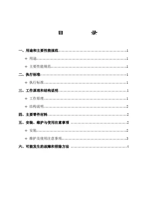
目录一、用途和主要性能规范 1✧用途1✧主要性能规范1二、执行标准 1✧执行标准1三、工作原理和结构说明 1✧工作原理1✧结构说明2四、主要零件材料 2五、安装、维护与使用注意事项 2✧安装2✧维护及使用注意事项3六、可能发生的故障和排除方法 4一、用途和主要性能规范✧用途蝶阀是一种适用性很强的新型产品,广泛用于建材、冶金、矿山、化工、电力、自来水、农业灌溉等,能远程控制或现场控制管道中介质的流量。
✧主要性能规范二、执行标准✧执行标准三、工作原理和结构说明✧工作原理蝶阀由阀门主体与手动、电动、气动液动装置及外围管线路等组成,其偏心密封结构,密封效果佳、使用寿命长,其开启、关闭迅速、安全。
蝶板围绕阀轴旋转来达到开启与关闭的一种阀,在管道上主要起切断和节流用。
蝶阀启闭件是一个圆盘形的蝶板,在阀体内绕其自身的轴线旋转,从而达到启闭或调节的目的。
蝶阀全开到全关通常是小于90°,蝶阀和蝶杆本身没有自锁能力,为了蝶板的定位,要在阀杆上加装蜗轮减速器。
采用蜗轮减速器,不仅可以使蝶板具有自锁能力,使蝶板停止在任意位置上,还能改善阀门的操作性能。
蝶阀的优点如下:1、启闭方便迅速、省力、流体阻力小,可以经常操作。
2、结构简单,体积小,重量轻。
3、可以运送泥浆,在管道口积存液体最少。
4、低压下,可以实现良好的密封。
5、调节性能好。
✧结构说明见外形连接尺寸图(附后)四、主要零件材料五、安装、维护与使用注意事项✧安装1.安装前仔细阅读产品使用说明书,核查阀门型号规格是否与所需相符。
2.安装前检查阀门内腔和密封面,不允许有污垢附着;连接管道内须清除干净,不得有异物存在。
3.安装使用前应进行阀门的启闭试验。
4.阀门可安装在水平管道或垂直管道上但不能倒装,请正确了解现场管道内介质流向,安装时请注意阀体上箭头为表示关闭时介质压力方向。
切勿反装。
5.安装时应使阀门保持关闭状态。
6.阀门在管道安装后,连接液动装置时,要注意液动推杆与阀门的平行度与角度.7.调试方法:阀门与液动装置连接安装完毕,用手动把阀门密封面调整到最合适吻合位置。

WGVLDefault/ConfigurationFor Use with AVK and EV and RV Series ActuatorsType overviewType Stroke WGVL2" [50 mm]Technical dataFunctional dataFluidchilled or hot water and steam Fluid Temp Range (water)Please Refer to Manufacturer's Valve Specifications Mounting Position 360°Applicable valve size2...6" [50...150]MaterialsHardware SS and Nickel plated steelHousing material Die cast aluminium and plastic casing Stem 316 stainless steel Stem adapter steelFrame, plate, base aluminum, steel (fits Warren Type 20,22,23,30, and 32) and Belimo G6/G7Collar steelCouplingGF Nylon supplied Suitable actuatorsNon-Spring EVB(X)RVB(X)Electrical fail-safeAVKB(X)For close-off pressure reference Select Pro or retrofit technical documentation.Product featuresThe default set up for a WGVL linkage will be factory installed along with an AVK or EV, RV series actuator. Included in the kit will be all the necessary hardware to facilitate mounting to the Warren valve.DimensionsType Weight WGVL5.7 lb [2.6 kg]WGVLEVB, EVX, RVB, RVXA B C D10.2" [260] 5.5" [140]9.2" [234]12.2" [310]AVKB, AVKXA B C D10.4" [264] 5.5" [140]10.3" [262]10.9" [276]EVX24-3FootnotesOn/Off, Floating Point, Non-Spring Return, Linear, 24 VTechnical dataElectrical dataNominal voltageAC/DC 24 V Nominal voltage frequency 50/60 Hz Power consumption in operation 3.5 W Power consumption in rest position 0.5 WTransformer sizing 6 VA (class 2 power source)Electrical Connection18 GA plenum cable, 3 ft [1 m], with 1/2"conduit connector, degree of protection NEMA 2 / IP54Overload Protection electronic throughout full stroke Electrical Protectionactuators are double insulated Functional dataActuating force motor 2500 N [560 lbf]Position feedback U note No FeedbackDirection of motion motor selectable with switch 0/1Manual override 5 mm hex crank (3/16" Allen), supplied Stroke2" [50 mm]Running Time (Motor)90 s /Running time motor variable 90 or 150 s Noise level, motor 60 dB(A)Position indicationMechanically, with pointer Safety dataDegree of protection IEC/EN IP54Degree of protection NEMA/UL NEMA 2Enclosure UL Enclosure Type 2Agency ListingcULus acc. to UL60730-1A/-2-14, CAN/CSA E60730-1:02, CE acc. to 2014/30/EU and2014/35/EU; Listed to UL 2043 - suitable for use in air plenums per Section 300.22(c) of the NEC and Section 602.2 of the IMC Quality Standard ISO 9001Ambient temperature -22...122°F [-30...50°C]Storage temperature -40...176°F [-40...80°C]Ambient humidity Max. 95% RH, non-condensing Servicingmaintenance-freeMaterialsHousing material Die cast aluminium and plastic casing† Use flexible metal conduit. Push the listed conduit fitting device over the actuator’s cable to butt against the enclosure. Screw in conduit connector. Jacket the actuators input wiring with listed flexible conduit. Properly terminate the conduit in a suitable junction box. Rated impulse Voltage 800V. Type of action 1. Control pollution degree 3.EVX24-3 Electrical installationINSTALLATION NOTESActuators may be connected in parallel. Power consumption and input impedance must beobserved.Actuators may also be powered by DC 24 V.Actuators with plenum cable do not have numbers; use color codes instead.Meets cULus requirements without the need of an electrical ground connection.Warning! Live electrical components!During installation, testing, servicing and troubleshooting of this product, it may be necessaryto work with live electrical components. Have a qualified licensed electrician or other individualwho has been properly trained in handling live electrical components perform these tasks.Failure to follow all electrical safety precautions when exposed to live electrical componentscould result in death or serious injury.Wiring diagramsOn/Off Floating PointTriac Source Triac Sink。

LHB24-3-100FootnotesApplicationBasic Non Fail-Safe actuator for controlling dampers in typical commercial HVAC applications.• Actuating force motor 150 N [35 lbf]• Nominal voltage AC/DC 24 V • Control On/Off, Floating pointTechnical dataElectrical dataNominal voltageAC/DC 24 V Nominal voltage frequency 50/60 HzNominal voltage rangeAC 19.2...28.8 V / DC 19.2...28.8 V Power consumption in operation 1.5 W Power consumption in rest position 0.5 W Transformer sizing 3 VAElectrical Connection 18 GA plenum cable, 1 m, with 1/2" NPT conduit connectorOverload Protectionelectronic throughout full stroke Functional dataActuating force motor 150 N [35 lbf]Direction of motion motor reversible with switch Manual override external push button Stroke4" [100 mm]Running Time (Motor)150 s / 100 mm Noise level, motor35 dB(A)Safety dataPower source ULClass 2 Supply Degree of protection IEC/EN IP54Degree of protection NEMA/UL NEMA 2Enclosure UL Enclosure Type 2Agency ListingcULus acc. to UL60730-1A/-2-14, CAN/CSA E60730-1:02CE acc. to 2014/30/EU and 2014/35/EU Quality Standard ISO 9001UL 2043 CompliantSuitable for use in air plenums per Section 300.22(C) of the NEC and Section 602 of the IMCAmbient humidity Max. 95% RH, non-condensing Ambient temperature -22...122°F [-30...50°C]Storage temperature -40...176°F [-40...80°C]Servicingmaintenance-free Weight Weight3.5 lb [1.6 kg]MaterialsHousing material UL94-5VA†Rated Impulse Voltage 4kV, Type of Action 1.AA.B, Control Pollution Degree 3.Product featuresFor on/off and floating point control of dampers in HVAC systems. Actuator sizing should be done in accordance with the damper manufacturer’s specifications.LHB24-3-100OperationTypical specificationThe actuator is not provided with and does not require any limit switches, but is electronically protected against overload. The anti-rotation strap supplied with the actuator will prevent lateral movement.The LHB(X)24-3... series provides 4, 8, or 12 in of linear force. The stroke of the gear rack can be adjusted on both sides in increments of 0.8 in [20 mm] by means of the mechanical end stops.When reaching the damper or actuator end position, the actuator automatically stops.The gears can be manually disengaged with a button on the actuator cover.The LHB(X)24-3… actuators use a sensorless brushless DC motor, which is controlled by an Application Specific Integrated Circuit (ASIC). The ASIC monitors and controls the actuator’s rotation and provides a digital rotation sensing (DRS) function to prevent damage to the actuator in a stall condition. Power consumption is reduced in holding mode.Floating point, on/off control damper actuators shall be electronic type, with integrated linear stroking arm. Actuators shall have brushless DC motor technology and be protected from overload at all positions of linear stroke. Actuators shall have reversing switch and manualoverride on the cover. Run time shall be constant and independent of torque. Actuators shall be cUL listed, have a 5-year warranty, and be manufactured under ISO 9001 International Quality Control Standards. Actuators shall be as manufactured by Belimo.AccessoriesElectrical accessoriesDescriptionType Signal simulator, Power supply AC 120 VPS-100Battery backup system, for non-spring return models NSV24 US Battery, 12 V, 1.2 Ah (two required)NSV-BAT Transformer, AC 120 V to AC 24 V, 40 VA ZG-X40Cable conduit connector 1/2"TF-CC US Mechanical accessoriesDescriptionType Ball joint suitable for damper crank arm KH8 / KH10KG10A Ball joint suitable for damper crank arm KH8KG6Ball joint suitable for damper crank arm KH8KG8Push rod for KG6 & KG8 ball joints (36” L, 5/16” diameter).SH8Rotary support, for linear actuator, for compensation of transverse forces Z-DS13/8”-16 shaft clevis for AHK/AH.Z-KSC Bracket for AHK/AH/LH linear actuators.ZG-119Electrical installationActuators with appliance cables are numbered.Provide overload protection and disconnect as required.Actuators may also be powered by DC 24 V.Actuators Hot wire must be connected to the control board common. Only connect common toneg. (-) leg of control circuits. Terminal models (-T) have no-feedback.Actuators may be connected in parallel if not mechanically linked. Power consumption andinput impedance must be observed.Floating Point - Triac SourceLHB24-3-100 Wiring diagramsOn/Off Floating PointFloating Point - Triac Source Floating Point - Triac SinkDimensions。

ZTH APTechnical dataElectrical dataNominal voltage AC 24 V, 50/60 Hz, DC 24 V (from actuator)Operating rangeAC 19.2...28.8 V / DC 21.6...28.8 V Power consumption Operation 1 WConnection Socket for connecting cable ZK1-GEN (3 m) supplied with connectorInterface USB 2.0USB socket type B, connecting cable (1 m) with socket A to B supplied Optional cablesZK2-GEN, ZK6-GENInterfaceCommunication Point to Point (PP), no bus mode possible (MP)Operating modesParameterisationPoint to Point (PP)Connection using service socket or connecting terminals on the actuatorMP level converter (ZIP function)Connection in control cabinet or via service socket on actuatorFor MP monitor operation, connection on MP-Bus OperationLCD display 2 x 16 characters, with background lighting Keysi / esc / ▲ / ▼ / OKSafetyProtection class III Safety extra-low voltage EMCCE according to 2004/108/EU Operating temperature 0...50 °C, non-condensing Non-operating temperature –20...50 °C, non-condensing Dimensions / weightDimensions L x W x D: 95 x 55 x 25 mm WeightApprox. 135 gService tool for parameterisable andcommunicative actuators / VAV controllers and HVAC performance devices from Belimo.•Connection via service socket on the device or MP/PP connection •ZIP USB functionSafety notes!•The device must not be used outside the specified field of application, especially not in aircraft or in any other airborne means of transport.•Only connection to Belimo devices with 24 V safety extra-low voltage and PP/MP interface permitted.•Changes to parameters etc. may only be performed following consultation with/specification from the OEM, device or mechanical/electrical contractor. Operating and adjustment regulations must be observed.Service tool for parameterisable and communicative actuatorsVAV controllers and HVAC performance devices from BelimoValve product range..-MF / ..-MP / ..-MPL / ..-MFT(2) /..-MOD / ..LONEPIV - pressure-independent characterisedP6..W..-MP available since 2011control valveFire damper actuator BF-TopLine with BKN230-24MPVAV product range VRD2 / VRD2-L available 1992-2007VRD3available since 2008VRP-M (VAV and STP applications)available since 2005NMV-D2..available 1992-2000LMV-D2M / NMV-D2M..available 2000-2006LMV-D2-MP / NMV-D2-MP / SMV-D2-MP.., LHV-D2-MP..available 2006-2011LMV-D2LON / NMV-D2LON available 2006- 2011LMV-D3-MP / NMV-D3-MP / SMV-D3-MP.., LHV-D3-MP..available since 2011LMV-D3LON / NMV-D3LON available since 2011LMV-D3-MOD / NMV-D3-MOD available since 2012 HVAC final controlling elements According to system description (e.g. Energy Valve)sharedlogic According to system descriptionConnectionConnection and supply The ZTH AP is supplied via the actuator. The connection is set up•either directly on the service socket of the actuator•or via PP/MP connection (U5), e.g. connection socket, control cabinet and room controllerCR24.Type of connection and connection cable Suitable cableZK1-GENZK2-GENZK4-GENZK6-GENService tool for parameterisable and communicative actuatorsVAV controllers and HVAC performance devices from BelimoDirect connection to the MP-Bus or MP master is not possible with the ZTH AP .RightWrongConnection via service socket - local connection with ZK1-GEN cableBelimo PC-ToolZK1-GENUSB 2.02124VGNDi esc okUSBMPBELIMOConnection via connecting cable - local connection with ZK2-GEN cableAC 24 V ~T_Connection in the MP-Bus systemNoteThe USB driver required will be automatically installed with PC-Tool version 3.9 or higher. For older versions of the PC-Tool, the driver can be downloaded from and installed separately.ZIP function connectionService tool for parameterisable and communicative actuatorsVAV controllers and HVAC performance devices from BelimoZIP function connectionPC-Tool as MP master•Actuator parameterisation via MP-Bus•Specification of setpoints for simulation of actuators via MP-Bus •Reading in of sensors that are connected to the MP actuator •Recording of graphic trendsPC-Tool connection with ZK6-GEN, ZK4-GEN on Belimo gateways•For connection to UK24MOD and UK24BAC, use the ZK6-GEN cable.•For connection to UK24EIB and UK24LON, use the ZK4-GEN cable.Note Interrupt connection between ZTH AP and MP master before using the ZIP function.*Service tool for parameterisable and communicative actuatorsVAV controllers and HVAC performance devices from BelimoConnection with ZIP functionPC-Tool as monitorCheck the MP communication with the MP monitor tool (module of PC-Tool V3.x).PC-Tool with monitor function / connection: ZK2-GEN to MP masterPC-Tool with monitor function / connection: tool socket with ZK6-GEN, ZK4-GENMP-MasterService tool for parameterisable and communicative actuatorsVAV controllers and HVAC performance devices from BelimoOperationWhen the ZTH AP is connected to the Belimo actuator, the operating device starts and data isread from the connected device. The available adjustment and operating options are displayedin accordance with the device type. The available setting parameters are listed in the productdocumentation for the actuators. See Operating elements LCD display- Background lighting- Display with 2 x 16 charactersKey function▼ and ▲Forward /backwardChange value / statusOK Confirm entry,go to submenuESC Abort entry,leave submenu,discard changei Shows additional information(if available)- RJ12 connection socket- USB connection socket for communication with PCLanguage setting, unit depiction Language and units can be set in the Configuration menu.Operation Operating is context-related, i.e. the user sees only the options available for the connecteddevice. The corresponding Configuration table is read from the actuator for this purpose.In addition to the parameter type, this table also contains the corresponding divisions, e.g.:minimum running time which can be set, type etc. Non-relevant options are not displayed.Menu structure, handlingStarting / endingunplugging it.Device specifications/Technical data For a more detailed description, including setting parameters, please refer to the respectiveseparate product information. See ¦ Documentation.Starting configuration 1. Press the key (OK) while simultaneously plugging in the connecting cable.2.Configuration menu display appears.Configuration menu Option / Display Setting ProductrangeExplanationEmpty cache Yes / No Function to delete data profiles ofHVAC performance devices fromthe local cacheBacklight After 0..255 sec off /always active Setting for duration of backlight in secondsShow favourites Disabled/ after1…65535 s HVACperformancedevices(EnergyValve)Alternating display of the first 3values after the set timeOEM number0…65535VAVAdvanced Mode 1)Yes / No VAVFireprotectionModbus Enabled settings:–VAV: direction of rotation–VAV: set Vmin / Vmax to original values (call up OEM setting)–BF-Top: adaption–Modbus: basic addressExpert Mode 1)Yes / No VAVValves Enabled settings:–VAV: switching mode–VAV: V‘mid parameter–VAV: altitude compensationPICCV function Yes / No Valves Belimo US:Enable PICCV Wizard function Power supplymeasurementValue V (AC)Pressure unit Pa / in WC VAVFlow unit (water)m3/h / l/min / gpm ValvesFlow unit (air)m3/h / l/s / cfm VAVExit configuration ESC1) Only activate this option as needed and with the respective know-how. Adjustment of the respective parameters requires special expertise.MP addressModbus actuatorsModbus-specific communication settings of an actuator with integrated Modbus interface (..-MOD).Device identificationThe following menu tree shows the basic functions which are identical for all devices.Service tool for parameterisable and communicative actuatorsVAV controllers and HVAC performance devices from BelimoFunctions for damper / rotary valve product rangeMenu tree The ZTH AP recognises the device family of the connected device automatically. The menu andthe options available are shown related to the connected device.Adjustment/display optionsLM24A-MP.Service tool for parameterisable and communicative actuatorsVAV controllers and HVAC performance devices from BelimoFunctions for globe valve product rangeMenu treeThe ZTH AP recognises the device family of the connected device automatically.The menu and the options available are shown related to the connected device.Adjustment/display optionsNVK24A-MP-TPC.Functions for EPIV - pressure-independent characterised control valveMenu treeAdjustment/display optionsEPIV.Service tool for parameterisable and communicative actuatorsVAV controllers and HVAC performance devices from BelimoFunctions for VAV product rangeMenu treeThe following menu tree corresponds to the new VAV-Compact D3 generation: L/N/SMV-D3-MP, LHV-D3-MP, L/ NMV-D3LON , L/MNV-D3-MOD 1)1)For Modbus settings, see previous description of "Basic functions for Modbus actuators"Adjustment/display optionsLMV-D3-MP.DeviationsVRD2 (1992-2007)Display showing actual value/setpoint in [% Vnom]Vmin in [% Vmax], Vmax in [% Vnom]Read only PP VRD3 (as of 2008)Display showing actual value/setpoint in [% Vnom]Vmin in [% Vnom], Vmax in [% Vnom] HW potentiometer setting «Tool →Read/write, otherwise → Read onlyPPVRP-M VAV Up to V2.16 Vmin in [% Vmax], Vmax in [% Vnom]As of V3.0 Vmin in [% Vnom], Vmax in [% Vnom]PP / MP1…8NMV-D2 (1992 – 2000)NMV-D2M (2000 –2006)Display showing actual value/setpoint in [% Vnom], Vmin in [% Vmax], Vmax in [% Vnom]PPPP / MP1 (8)Altitude compensation This function requires VAV-Compact D3 withfirmware V2.06 (03/2013) or higher and ZTH with firmware V2.01 or higher.Note: VAV-Universal actuatorsThe V-actuators L/N/SM24A-V, L/NMQ24A-SRV-ST, which fit the VAV universal controllers VR.., have a tool connection but are nevertheless not tool-capable.Service tool for parameterisable and communicative actuatorsVAV controllers and HVAC performance devices from BelimoFunctions for BF-TopLine fire damper actuatorsMenu treeAdjustment/display options BF-TopLine actuator.Functions for MPL actuatorsMenu treeAdjustment/display optionsMPL actuator.Range 0...100%(OPEN/CLOSE/Stop)Functions for room sensors MS24A-R0x-MPXMenu treeAdjustment/display optionsRoom sensor MS24A-R08-MPX(T, rH, CO2, VOC).Service tool for parameterisable and communicative actuatorsVAV controllers and HVAC performance devices from BelimoZIP functionsIn this configuration, the ZTH AP works as a level converter between the USB port of a PC and the Belimo MP device. The correct driver will be automatically installed on the PC when the ZTH AP is plugged in. As soon as the USB interface is connected, the ZTH AP switches to ZIP mode.Power supplyChecking the power supplyThe ZTH AP allows the "AC 24 V" power supply (III safety extra-low voltage) of the Belimo devices to be checked. Voltages >30V are not permitted!Application: e.g. commissioning, troubleshooting in the event of a malfunction.Measuring processEquipment: ZTH AP , ZK2-GEN Connect in the following order:•Connect free wires of the ZK2-GEN to AC 24 V.•White to GND (connection 1 actuator/VAV controller)•Blue to ~ (connection 2 actuator/VAV controller)•Do not connect third wire (turquoise)Start:Press the ZTH AP key (OK) while at the same time connecting the RJ12 plugSelect "AC measurement" function with arrow key (▼)End:"Supply okay" display: AC supply in the range 19.2 ... 28.8 VAC value: measured AC voltage (accuracy ±1.0 V provided that VHW >95%)Explanation of VHWThe VHW unit describes the relationship between the positive and negative half-wave.The deviation between the positive and negative half-wave value must not be too great. The following formula applies: positive HW / negative HW x 100 should be >80%:Possible problemsThe following factors influence the half-wave load:•Transformer dimensions too small•Maximum signal cable length between transformer and actuator exceededpositive HWnegative HWNoteIf the ZTH AP is connected to the PC, the display flashes a few times until the driver is installed on the PC.NoteOnly connect RJ12 plug to ZTH AP when starting!Connection as MP master (e.g. PC-Tool).If there is bus communication, this is indicated by Tx and Rx flashing.Connection for monitor function with PC-Tool.If there is bus communication, this is indicated by Tx and Rx flashing.Service tool for parameterisable and communicative actuatorsVAV controllers and HVAC performance devices from BelimoFirmware upgradeThe ZTH AP can be updated to the latest firmware version using the ZTH AP updater. The required software and the instructions for the upgrade can be downloaded from the download area of the Belimo website .CompatibilitiesFunction and handlingThe ZTH AP includes the complete functionality of all previous versions of the ZTH-GEN and ZTH-VAV.The hardware of the ZTH AP is not however compatible with the hardware of the ZTH-GEN. The updates for the ZTH-GEN cannot be loaded to the ZTH AP .In addition, the new ZTH AP supports the ZIP USB function. This can be used for the ZTH AP updates and also as a level converter USB/MP with the PC-Tool.ZEV The ZEV adjustment tool (1992 to 2007) is replaced by the ZTH AP . ZTH-VAVIs replaced by the ZTH AP .ZTH-GEN V2.xx / V3.xx / V4.xxIs replaced by the ZTH AP .NoteLatest information about firmware upgrades, version overviews, documentation:See Version overviewV 2.03V 2.02•Device identification for VRD2 / NMV-D2 corrected•New menu "Sensor monitoring of air bubbles" for the EPIV •Error correction: impairment of the sensor measurement at Y3•Error correction: impairment of the analogue setpoint at Y3V 2.01• Release of the ZTH and ZIP function。
362Installation and OperationNon-Spring ReturnPreliminary Steps1. Belimo actuators with NEMA 1 or NEMA 2 ratings should be mounted indoors in a dry, relatively clean environment free from corrosive fumes. If the actuator is mounted outdoors, a protective enclosure must be used to shield the actuator.2. For new construction work, order dampers with extended shafts. Instruct theinstalling contractor to allow space for mounting the Belimo actuator on the shaft. For replacement of existing gear train actuators, there are two options:A. From a performance standpoint, it is best to mount the actuator directly onto the damper shaft.B. If the damper shaft is not accessible, mount the non-spring return actuator with a ZG-NMA or ZG-GMA crank arm kit, and a mounting bracket (ZG-100, ZG-101, ZG-103, ZG-104)Damper torque loadings, used in selecting the correct size actuator, should be pro-vided by the damper manufacturer. If this information is not available, the following general selection guidelines can be used.Damper TypeTorque Loading Opposed blade, without edge seals, for non-tight close-off applications3 in-lb/sq. ft.Parallel blade, without edge seals, for non-tight close-off applications4 in-lb/sq. ft.Opposed blade, with edge seals, for tight close-off applications5 in-lb/sq. ft.Parallel blade, with edge seals, for tight close-off applications7 in-lb/sq. ft.The above torque loadings will work for most applications under 2 in. w.g. static pressure or 1000 FPM face velocity. For applications between this criteria and 3 in.w.g. or 2500 FPM, the torque loading should be increased by a multiplier of 1.5. If the application calls for higher criteria up to 4 in. w.g. or 3000 FPM, use a multiplier of 2.0.Torque Loading Chart1401201008060402002346810579D a m p e r A r e a (s q . f t .)Torque Loading (in-lb/ sq. ft.)If more torque is required than one GM can provide, GM24B, GMB24-SR or GMX24-MFT may be installed on the same shaft.Table of ContentsPAGEGeneral MountingStandard .............................................................270 Reversible Clamp ................................................271 Linear .................................................................272 Rotary .................................................................273 Retrofit Brackets .................................................275OperationElectrical .............................................................276 Mechanical .........................................................277WiringGeneral ...............................................................278 Accessories ........................................................279Startup and Checkout . (282)M 40024 - 05/10 - S u b j e c t t o c h a n g e . © B e l i m o A i r c o n t r o l s (U S A ), I n c .363SEE NEXT PAGE FOR STANDARD MOUNTING INSTRUCTIONS.A*B C**D LMB 1/4” to 5/8”5/16” to 9/16” 1.5” 4 to 5 ft-lb LMQB 1/2” to 1.05”3/8” to 11/16” 1.5” 6 to 7 ft-lb NMB 1/2” to 1.05”3/8” to 11/16” 1.5” 6 to 7 ft-lb NMQB 1/2” to 1.05”3/8” to 11/16” 1.5” 6 to 7 ft-lb AMB 1/2” to 1.05”3/8” to 11/16” 1.5” 6 to 7 ft-lb AMQB 1/2” to 1.05”7/16” to 11/16” 1.5” 6 to 7 ft-lb GMB1/2” to 1.05”7/16” to 11/16”1.5”6 to7 ft-lb* LMB standard clamp has max 5/8” diameter. Accessory clamp K-LM20 can be mounted for sizes up to 3/4” diameter. NM and AM clamps have an insert that self-centers on the following diameter shafts: 1/2” (default), 3/4” and 1.05”. GM clamps have an insert that self-centers on 3/4” diameter.** Shorter with reversible clamp for NMB, AMB, and GMB.Installation InstructionsQuick-Mount Visual Instructions for Mechanical InstallationCA B1212112365°2155°10D214LM Universal Mounting BracketM 40024 - 05/10 - S u b j e c t t o c h a n g e . © B e l i m o A i r c o n t r o l s (U S A ), I n c .364Mounting InstallationReversible Clamp Quick Mount (NM, AM, GM)1 Turn the damper shaft until the blades are fully closed.2➀Slip the actuator’s universal clamp over the damper shaft. Make sure that the duct and the controls on the cover are accessible. Place the actuator in the desired mounting position.➁ Hand tighten the two nuts on the actuators universal clamp.3➀ Disengage the actuator gear train by pressing the manual override button and rotate the clamp until centered.➁ Slide the anti-rotation strap up under the actuator so it engages the actuator at the center cutout. Bend the bracket as needed to support the rearof the actuator. Secure to ductwork with self-tapping screws (No. 8 recom-mended).4➀ Loosen the nuts on the universal clamp. Press the manual override button and rotate the clamp to about 5° from the closed position (1/16 to 1/8” between stop and clamp).➁ Tighten the two nuts on the universal clamp with a 10 mm wrench (see table for required torque).5➀ Snap on the refl ective position indicator.➁ Adjust end-stops, if required.6Mount actuators indoors. If mounted outdoors, use approved protective enclo-sure.The damper is now fully closed but the actuator is 5° from fully closed. This is called “pre-loading” the actuator. When the actuator is powered and sent to the closed position: it will put its full torque on the shaft compressing the edge and blade seals. This ensures that the damper will meet its leakage rating. The actuator is electroni-cally protected from overload and will not be damaged.Testing the Installation Without Power1. Disengage the gear train with the manual override button and move the shaft from closed to open to closed. Ensure that there is no binding and that the damper goes fully open and closes with 5° of actuator stroke left.2. Correct any problems and retest.M 40024 - 05/10 - S u b j e c t t o c h a n g e . © B e l i m o A i r c o n t r o l s (U S A ), I n c .Mounting InstallationLinear Quick Mount (LH, AH)1Ø max. 0.3" [8]20.08" [2]0.8"[20] 0.8"[20]3 M8Z-DS1Z-DS1±10°M424-5/1-Subjecttochange.©BelimoAircontrols(USA),Inc.365366Mounting InstallationRotary Quick Mount (LU)K-LUm i n .1/2" [13]5/16"…1/2" [8...12]K-LU Shaft ClampZDB-LU Angle of Rotation Limiter1306090120150180210240270300330+33030027240210180150120906030+330300270240210181501209060303060901201501802102402703003300°...120°03330027024021018015012090603003330272402101801501209060300°...270°3060912015018021242730330030609021501801024027300330ZDB-LU Angle of Rotation LimiterM 40024 - 05/10 - S u b j e c t t o c h a n g e . © B e l i m o A i r c o n t r o l s (U S A ), I n c .USA 367Mounting InstallationQuick Mount, Direct Coupled CMB24-3(-T) / CMB120-31234M 40024 - 05/10 - S u b j e c t t o c h a n g e . © B e l i m o A i r c o n t r o l s (U S A ), I n c .3681When replacing an actuator, whether Belimo or other, be sure to consider the ap-plication parameters before selecting the replacement. The new product may notbe the best fi t for the application. Example would be a Belimo AM24 US mounted to a valve linkage. The direct replacement of the actuator is AMB24-3. However, the AM24 US and the AMB24-3 are different lengths, the linkage would need to be replaced as well.Instead of replacing the linkage the retrofi t bracket Z-SMA and Z-GMA can be used to extend the location of the anti-rotation bracket to match the location of the anti-rotation bracket of discontinued Belimo actuators.NOTE: LM and LMB are the same size.Mounting InstructionsRetrofi t Brackets (Z-SMA and Z-GMA)3 Nm2NMGM1xZ-NMAfor replacing NM actuators2 xZ-GMAfor replacing GM actuators2xZ-SMAfor replacing AM and SM actuatorsSMAMM 40024 - 05/10 - S u b j e c t t o c h a n g e . © B e l i m o A i r c o n t r o l s (U S A ), I n c .Operation Electrical FeaturesGeneralBelimo non-spring return actuators utilize Halomo sensorless Brushless DC motor technology developed by Belimo. The non-spring return actuators use this motor in conjunction with an Application Specific Integrated Circuit (ASIC). The Halomo ASIC provides the intelligence to provide a constant rotation rate to prevent damage to the actuator.InitializationWhen a power source is applied the motor carries out an initialization of the actuator. The purpose of this initialization is to determine the mechanical angle of rotation and to adapt the running time to the angle of rotation. When power is applied, the internal microprocessor recognizes that the actuator is at its full-safe position and uses this position as the base for all of its calculations.Brushless DC Motor OperationBelimo’s Halomo sensorless brushless DC motor spins by reversing the poles of stationary electromagnets housed inside rotation permanent magnets. The electromagnetic poles are switched by a special ASIC developed by Belimo. Unlike the conventional DC motor, there are no brushes to wear or commutators to foul. Motor Position DetectionBelimo's Halomo motor technology is a sensorless, brushless DC motor. The Halomo technology eliminates the need for potentiometers for positioning. The Halomo ASIC detects the spinning rotor by monitoring the back EMF of the motor poles. The ASIC counts these pulses and calculates position within 1/3 of a motor revolution.Overload ProtectionThe Belimo non-spring return actuators are electronically protected from overload at all angles of rotation by digital technology in the ASIC. The ASIC circuitry constantly monitors the rotation of the brushless DC motor inside the actuator and stops the pulsing to the motor when it senses an overload. The motor remains energized and produces full rated torque when in overload.The overload filtration helps increase the actuators installed life expectancy by filtering out unnecessary control signal changes or end-stop pulsing while in overload. This helps ensure that dampers are fully closed and that edge and blade seals are always properly compressed.All Belimo actuators have built-in brushless DC motors which provide better accuracy and longer service life. Belimo non-spring return actuators are designed with a unique non-symmetrical deadband. The actuator follows an increasing or decreasing control signal with a 75 mV resolution. If the signal changes in the opposite direction, the actuator will not respond until the control signal changes by175 mV. This allows these actuators to track even the slightest deviation very accurately, yet allowing the actuator to “wait” for a much larger change in control signal due to control signal instability.SatisfiedControl PositionMinimumControl Resolution75 mVActuator responds to a 75 mV signal whennot changing direction from stop position.SatisfiedControl Position Minimum ReversedControl DeadbandPrior to Normal Control175 mVActuator responds to a 175 mV signal whenreversing direction from stop position.369370Manual Override Button10 VDC 10 VDC2 VDC Direction of Rotation Switch65°OperationMechanical FeaturesThe Belimo non-spring return actuators have a black, “manual override button” located on the top of the housing. Press this button and the gear train isdisengaged so the damper shaft can be moved manually. Release the button and the gear train is re-engaged.Use the manual override to test the installation without power. For tight shut-off the damper should close with 5° of actuator stroke left.Non-spring return actuators have a reversing switch on the cover. Switch position indicates start point. For the non-spring return, with the switch in position 1, the actuator rotates clockwise with an decrease in voltage or current. With the switch in position 0, the actuator rotates counterclockwise with an decrease in voltage or current.The non-spring return rotates clockwise when the switch is in the 1 position and power is applied to wire #2. When power is applied to wire #3 the actuator rotates counter clockwise. Rotating the switch to 0 reverses the control logic.During checkout, the switch position can be temporarily reversed and the actuator will reverse its direction. This allows the technician a fast and easy way to check the actuator operation without having to switch wires or change settings on the thermostat. When the check-out is complete, make sure the switch is placed back to its original position.The adjustable stops are needed when there is no damper stop or if you want the damper to stop rotating before it reaches its stops. The non-spring return actuators can be indefinitely stalled in any position without harm.1. Loosen the two end stops with a No. 2 Phillips head screwdriver being careful not to unscrew the captive nut under the slot.2. Move the stops (in 2.5° steps) to the desired position and re-tighten the screws.M 40024 - 05/10 - S u b j e c t t o c h a n g e . © B e l i m o A i r c o n t r o l s (U S A ), I n c .。
71363-00001.BI N S TA L L AT I O N I N S T R U C T I O N SBelimo Energy Valve™InstallationInletThe Energy Valve requires a section of straight pipe on the valve inlet to guarantee sensor accuracy. The length should be at least 5 diameters long. 2½” [DN65] 5 x nominal pipe size = 12½” [317 mm] 3” [DN80] 5 x nominal pipe size = 15” [381 mm] 4” [DN100] 5 x nominal pipe size = 20” [508 mm] 5” [DN125] 5 x nominal pipe size = 25” [635 mm] 6” [DN150] 5 x nominal pipe size = 30” [762 mm]Outlet LengthNo requirements for outlet length.Elbows can be installed directly after the valve.Remote Sensor Installation:A thermo well is provided with the remote temperature sensor. The well should be installed on the pipe prior to installing the remote temperature sensor. The remote temperature sensor should be installed on the opposite pipe entering the coil from where the Energy Valve is installed. A ½” NPT female union should be welded on the pipe to allow the installation of the thermo well.The Energy Valve is equipped with a 32 ft. (10m) cable for the remote sensor. If a shorter remote sensor cable is required, the cable is also available in the following sizes:4.9 ft (1.5m), 9.8 ft. (3m) or 16.4 ft (5m). Please order the appropriate size for the application.OrientationEnergy Valves shall be installed with flow in the direction of the arrow on the valve body.The valve assembly can be installed in a vertical or horiz talled horizontal arrangement, as long as the actuator is positioned to avoid condensation from dripping onto the actuator.How to build the remote well08/17 - S u b j e c t t o c h a n g e . © B e l i m o A i r c o n t r o l s (U S A ), I n c .Installation Instructions Belimo Energy ValvePipingThe Energy Valve is recommended to be installed on the return side of the coil. This diagram is for typical applications only. Consult engineering specification and drawings for particular circumstances. Install provided thermal well on the other side of the coil (T1). P/T ports are recommended on either side of the valve and the supply side of the heat transfer device to allow for pressure/flow measurement/calculation.It is not necessary to install one strainer per unit. Belimo recommends installing one strainer per system. If the system has multiple branches,it is recommended to install one strainer per branch. The Energy Valve cannot be piped in a parallel orientation.General WarningsValve should not be used for combustible gas applications. Gas leaks and explosions may result. Do not install in systems, which exceed the ratings of the valve.• Avoid installations where valve may be exposed to excessive moisture, corrosive fumes, vibration, high ambient temperatures, elements, or high traffic areas with potential for mechanical damage.• Valve assembly location must be within ambient ratings of actuator. If temperature is below -22°F a heater is required.• The valve assembly will require heat shielding, thermal isolation, or cooling if combined effect of medium and ambient temperatures – conduction, convection, and radiation– is above 122°F for prolonged time periods at the actuator.• Visual access must be provided. Assembly must be accessible for routine schedule service. Contractor should provide unions for removal from line and isolation valves.• Avoid excessive stresses. Mechanical support must be provided where reducers have been used and the piping system may have less structural integrity than full pipe sizes. • Sufficient upstream piping runs must be provided to ensure proper valve capacity and flow response. See installation section for details.• Life span of valve stems and O-rings is dependent on maintaining non-damaging conditions. Poor water treatment or filtration, corrosion, scale, other particulate can result in damage to trim components. A water treatment specialist should be consulted.• It is not necessary to install one strainer per unit. Belimorecommends installing one strainer per system. If the system has multiple branches, it is recommended to install one strainer per branch.WARNING: Lift Energy Valve from valve body. Do not lift this valve by the actuator. Lifting the valve body by the actuator can break the linkage and void the warranty.1. Inspect shipping package, valve, linkage, and actuator for physicaldamage. If shipping damage has occurred notify appropriate carrier. Do not install.2. If a replacement, remove existing valve, linkage, and actuator fromthe piping system.3. If actuator and linkage are removed, they must be reinstalledcorrectly. The actuator must be rotated so that the valve seats properly for close off.4. Install valve with the proper ports as inlets and outlets. Check thatinlet and outlet of 2-way valves are correct. Flow direction arrows must be correct.5. Blow out all piping and thoroughly clean before valve installation.6. Clean flanges with wire brush and rag. Clean pipes, flanges, andvalve flanges before installation; check for any foreign material that can become lodged in trim components. Strainers should be cleaned after initial startup.7. Valve must be installed with the stem towards the vertical, notbelow horizontal.8. These valves are designed to be installed between ANSI Class125/150 flanges.9. Carefully follow installation using ANSI piping practices.10. The flow sensor cannot be rotated 90 degrees as it will not readflow.71873-00001I N S TA L L AT I O N I N S T R U C T I O N SBelimo Energy Valve ™for ANSI 250 FlangedInstallationInletThe Energy Valve requires a section of straight pipe on the valve inlet to guarantee sensor accuracy. The length should be at least 5 diameters long. 2½” [DN65] 5 x nominal pipe size = 12½” [317 mm] 3” [DN80] 5 x nominal pipe size = 15” [381 mm] 4” [DN100] 5 x nominal pipe size = 20” [508 mm] 5” [DN125] 5 x nominal pipe size = 25” [635 mm] 6” [DN150] 5 x nominal pipe size = 30” [762 mm]Outlet LengthNo requirements for outlet length.Elbows can be installed directly after the valve.Remote Sensor Installation:A thermo well is provided with the remote temperature sensor. The well should be installed on the pipe prior to installing the remote temperature sensor. The remote temperature sensor should be installed on the opposite pipe entering the coil from where the Energy Valve is installed. A ½” NPT female union should be welded on the pipe to allow the installation of the thermo well. The Energy Valve is equipped with a 32 ft. (10m) cable for the remote sensor. If a shorter remote sensor cable is required, the cable is also available in the following sizes: 4.9 ft (1.5m), 9.8 ft. (3m) or 16.4 ft (5m). Please order the appropriate size for the application.OrientationEnergy Valves shall be installed with flow in the direction of the arrow on the valve body.The valve assembly can be installed in a vertical or horizontal arrangement, as long as the actuator is positioned to avoid condensation from dripping onto the actuator.How to build the remote well5 x Nominal Pipe Size (NPS)ANSI Class 25008/17 - S u b j e c t t o c h a n g e . © B e l i m o A i r c o n t r o l s (U S A ), I n c .Installation Instructions Belimo Energy ValvePipingThe Energy Valve is recommended to be installed on the return side of the coil. This diagram is for typical applications only. Consult engineering specification and drawings for particular circumstances. Install provided thermal well on the other side of the coil (T1). P/T ports are recommended on either side of the valve and the supply side of the heat transfer device to allow for pressure/flow measurement/calculation.It is not necessary to install one strainer per unit. Belimo recommends installing one strainer per system. If the system has multiple branches, it is recommended to install one strainer per branch. The Energy Valve cannot be piped in a parallelorientation.General Warnings Valve should not be used for combustible gas applications. Gas leaks and explosions may result. Do not install in systems, which exceed the ratings of the valve.• Avoid installations where valve may be exposed to excessive moisture, corrosive fumes, vibration, high ambient temperatures, elements, or high traffic areas with potential for mechanical damage.• Valve assembly location must be within ambient ratings of actuator. If temperature is below -22°F a heater is required.• The valve assembly will require heat shielding, thermal isolation, or cooling if combined effect of medium and ambient temperatures – conduction, convection, and radiation– is above 122°F for prolonged time periods at the actuator.• Visual access must be provided. Assembly must be accessible for routine schedule service. Contractor should provide unions for removal from line and isolation valves.• Avoid excessive stresses. Mechanical support must be provided where reducers have been used and the piping system may have less structural integrity than full pipe sizes. • Sufficient upstream piping runs must be provided to ensure proper valve capacity and flow response. See installation section for details.• Life span of valve stems and O-rings is dependent on maintaining non-damaging conditions. Poor water treatment or filtration, corrosion, scale, other particulate can result in damage to trim components. A water treatment specialist should be consulted.• It is not necessary to install one strainer per unit. Belimorecommends installing one strainer per system. If the system has multiple branches, it is recommended to install one strainer per branch.WARNING: Lift Energy Valve from valve body. Do not lift this valve by the actuator. Lifting the valve body by the actuator can break the linkage and void the warranty.1. Inspect shipping package, valve, linkage, and actuator for physicaldamage. If shipping damage has occurred notify appropriate carrier. Do not install.2. If a replacement, remove existing valve, linkage, and actuator fromthe piping system.3. If actuator and linkage are removed, they must be reinstalledcorrectly. The actuator must be rotated so that the valve seats properly for close off.4. Install valve with the proper ports as inlets and outlets. Check thatinlet and outlet of 2-way valves are correct. Flow direction arrows must be correct.5. Blow out all piping and thoroughly clean before valve installation.6. Clean flanges with wire brush and rag. Clean pipes, flanges, andvalve flanges before installation; check for any foreign material that can become lodged in trim components. Strainers should be cleaned after initial startup.7. Valve must be installed with the stem towards the vertical, notbelow horizontal.8. -250 models are designed to be installed between ANSI Class250/300 flanges only.9. Carefully follow installation using ANSI piping practices.10. During the installation the actuator and the flow sensor can beremoved from the valve. The two components should be removed together and the sensor wire must not be disconnected from the actuator.The sensor and valve bodies should not be disassembled.Disassembly can damage the valve components and will void the warranty.When assembling the flow sensor back in the body the holding nutshould be hand tighten. No tools should be used to tighten the nut. This can damage the thread of the nut.11. In cases where the valve body is electrically isolated from thewater pipe, an earth ground must be installed in order for the sensor to work properly. Earth ground is connected directly on the sensor body. A connection point is provided on the flange of the sensor body.12. The flow sensor cannot be rotated 90 degrees as it will not readflow.InstallationINSTRUCTION MANUALEVX, AVKX Actuators with Belimo Energy Valves ™71875-0000111/15 - S u b j e c t t o c h a n g e . © B e l i m o A i r c o n t r o l s (U S A ), I n c .WIRING DIAGRAMSBlk (1) Common TRed (2) Hot +Wht (1) S Red (2) S Wht (1) S Red (2) S 24 VAC T ransformer Line VoltsC a b l eT C a b l e T C a b l e 1Wht (3) Y-Input O rg (5) U-O utput Pnk (6) C -BACnet MS/TP -Gry (7) C -BACnet MS/TP +A2 to 10 VDCFeedback SignalControl Signal(+)(+)(-)(-)2 to 10 VDC Line VoltsFeedback Signal Control Signal4-20 mA 2-10 VDC4-20 mABlk (1) CommonTRed (2) Hot +Wht (1) S Red (2) S Wht (1) S Red (2) S 24 VAC T ransformerLine VoltsC a b l e T C a b l e T C a b l e 1Wht (3) Y-Input O rg (5) U-O utputPnk (6) C -BACnet MS/TP -Gry (7) C -BACnet MS/TP +A318(BACnet MS/TP)24 VAC TransformerLine Volts。
B263•ApplicationStainless Steel Ball and StemType overviewType DN B26365Technical dataFunctional dataValve size 2.5" [65]Fluidchilled or hot water, up to 60% glycol Fluid Temp Range (water)0...212°F [-18...100°C]Body Pressure Rating 400 psi Close-off pressure ∆ps 100 psiFlow characteristic equal percentage Servicing maintenance-free Flow Pattern 2-way Leakage rate0% for A – AB Controllable flow range 75°Cv110Cv Flow RatingA-port: as stated in chart B-port: 70% of A – AB CvMaterialsValve body Nickel-plated brass body Stem stainless steel Stem seal EPDM (lubricated)SeatPTFE Characterized disc TEFZEL®Pipe connection NPT female ends O-ring EPDM (lubricated)Ballstainless steel Suitable actuators Non-Spring ARB(X)SpringAFRB(X)Safety notesWARNING: This product can expose you to lead which is known to the State of California to cause cancer and reproductive harm. For more information go to Product featuresThis valve is typically used in air handling units on heating or cooling coils, and fan coil unit heating or cooling coils. Some other common applications include Unit Ventilators, VAV box re-heat coils and bypass loops. This valve is suitable for use in a hydronic system with variable flow.B263 Flow/Mounting detailsTwo-way valves should be installed with thedisc upstream.DimensionsType DNB26365ARB, ARXA B C D E F H1H211.0" [280] 5.6" [141]8.0" [203] 6.0" [152] 2.8" [71] 2.8" [71] 1.9" [48]0.8" [20]AFRB, AFRXA B C D E F11.5" [293] 5.6" [141]8.6" [219] 6.6" [168] 2.0" [51] 2.0" [51]AFRB N4, AFRX N4A B C D E F13.0" [330] 5.6" [141]10.3" [262]9.3" [235] 3.4" [86] 3.4" [86]B263ARB N4, ARX N4, NRB N4, NRX N4A B D E F11.4" [289] 5.6" [141]8.0" [203] 3.1" [80] 3.1" [80]ARQB, ARQXA C D E F H1H29.9" [251]8.1" [206] 6.1" [155] 2.3" [58] 2.3" [58]0.8" [20]0.6" [15]ARX24-SR-T N4FootnotesNEMA 4X, Modulating Control, Non-Spring Return, 24 V, for DC 2...10 V or 4...20 mATechnical dataElectrical dataNominal voltageAC/DC 24 V Nominal voltage frequency 50/60 Hz Power consumption in operation 2.5 W Power consumption in rest position 0.4 WTransformer sizing 5 VA (class 2 power source)Electrical Connection Terminal blocksOverload Protectionelectronic thoughout 0...90° rotation Functional dataOperating range Y 2...10 VOperating range Y note 4...20 mA w/ ZG-R01 (500 Ω, 1/4 W resistor)Input Impedance 100 kΩ for 2...10 V (0.1 mA), 500 Ω for 4...20 mA Position feedback U 2...10 V Position feedback U note Max. 1 mADirection of motion motor selectable with switch 0/1Manual override under cover Angle of rotation 90°Angle of rotation note adjustable with mechanical stop Running Time (Motor)90 s / 90°Running time motor variable 90 or 150 s Noise level, motor 45 dB(A)Position indicationpointer Safety dataDegree of protection IEC/EN IP66/67Degree of protection NEMA/UL NEMA 4XEnclosure UL Enclosure Type 4XAgency Listing cULus acc. to UL60730-1A/-2-14, CAN/CSA E60730-1:02, CE acc. to 2014/30/EU Quality Standard ISO 9001Ambient temperature -22...122°F [-30...50°C]Ambient temperature note -40...50°C for actuator with integrated heating Storage temperature -40...176°F [-40...80°C]Ambient humidity Max. 100% RH Servicingmaintenance-freeMaterialsHousing material Die cast aluminium and plastic casing†Rated Impulse Voltage 800V, Type of action 1, Control Pollution Degree 4.ARX24-SR-T N4 AccessoriesElectrical accessories Description TypeBattery backup system, for non-spring return models NSV24 USBattery, 12 V, 1.2 Ah (two required)NSV-BAT Electrical installationINSTALLATION NOTESProvide overload protection and disconnect as required.Actuators may be connected in parallel. Power consumption and input impedance must beobserved.Actuators may also be powered by DC 24 V.Only connect common to negative (-) leg of control circuits.A 500 Ω resistor (ZG-R01) converts the 4...20 mA control signal to 2...10 V.Actuators are provided with a numbered screw terminal strip instead of a cable.Meets cULus requirements without the need of an electrical ground connection.Warning! Live electrical components!During installation, testing, servicing and troubleshooting of this product, it may be necessaryto work with live electrical components. Have a qualified licensed electrician or other individualwho has been properly trained in handling live electrical components perform these tasks.Failure to follow all electrical safety precautions when exposed to live electrical componentscould result in death or serious injury.Wiring diagrams2...10 V / 4...20 mA ControlDimensions。
P 10410 - 09/14 - S u b j e c t t o c h a n g e . © B e l i m o A i r c o n t r o l s (U S A ), I n c .Belimo Pressure Independent Valve Flow Verification and CommissioningFigure APIVs are very different from pressure dependent control valves (standard control valves). Pressure variations in the system do not affect flow through the PIV. PIVs do not require additional flow regulating devices (e.g. – circuit setters and automatic flow limiting devices). This makes the Testing and Balancing (TAB)/Commissioning process much different from standard control valves. This document details the flow verification and commissioning procedures for a Pressure Independent Valve (PIV). These procedures are not mandatory to ensure proper operation of PIV.When using PIV, Electronic Pressure Independent Valve (EPIV), or Energy Valve (EV), flow verification can be performed using the valve’s built-in flow sensor and a hand-held tool (ZTH US) that connects to the valve. However, if independent verification is required, the use of 3 P/T ports is recommended.NOTE: When using mechanical PIVs, Pressure Independent Characterized Control Valves (PICCV), it is essential that the mechanical contractor install three (3) independent pressure/temperature ports (P/T ports) if the PICCV is not supplied with integrated ports. For P/T port locations, refer to Figure A in this document.External P/T ports allow for independent verification of proper PIV operation and these ports allow for future comprehensive troubleshooting and diagnosis.For proper and accurate flow verification of mechanical PIV, it isessential that the mechanical contractor install P/T ports as shown in Figure A. Some PIVs may be ordered with integrated P/T ports.•P/T port #1 and P/T port #2 are used to measure the pressure and temperature drop across the cooling or heating coil. This information in combination with the coil flow curves can be used to calculate flow and delta T.•P/T port #2 and P/T port #3 are used to measure pressure drop across the PIV. PIVs must have 5 – 50 psid (11.5 ft – 115 ft H 2O) (or per manufacturer’s specification) pressure drop across the valve only. PIVs must be commanded to design flow position via analog or BMS (Building Management System) signal. Do not manually open the valve with the override handle to check for design flow or pressure. The required operating pressure drop range is necessary to ensure pressure independent operation of the PIV.P141-9/14-Subjecttochange.©BelimoAircontrols(USA),Inc. Belimo Pressure Independent Valve Flow Verification and CommissioningMechanical PIV Pre-Flow Verification Checklist• Verify that system is purged of air and filled to proper pressure.• Verify that each PIV has the manufacturer’s required operatingpressure drop range across P/T ports 2 and 3 (Figure A).• Verify proper pump operation per manufacturer’s specifications.• Verify proper supply water temperature is available and is at designtemperature.• Proper air filter maintenance has been completed.• Fan belts are in proper working order.• Heat transfer devices (coils) are clean.• Strainers are clean.• All manual shutoff valves are open.• All bypass valves are closed.• No automatic or manual balancing valves exist. If they do exist,they must be set fully open and locked not interfere withthe pressure independency function of the PIV.Electronic PIV Pre-Flow Verification Checklist• Verify that system is purged of air and filled to proper pressure.• Verify that each electronic PIV is set to pressure independent/flow control mode.• If the PIV is an Energy Valve, the Delta T Manager™ must bedisabled during the flow verification and commissioning procedure.• Verify that each PIV has the manufacturer’s required operatingpressure drop range across P/T ports 2 and 3 (Figure B).• Verify proper pump operation per manufacturer’s specifications.• Verify proper supply water temperature is available and is at designtemperature.• Proper air filter maintenance has been completed.• Fan belts are in proper working order.• Heat transfer devices (coils) are clean.• Strainers are clean.• All manual shutoff valves are open.• All bypass valves are closed.• A flow verification tool is available (ZTH US).• No automatic or manual balancing valves exist. If they do exist,they must be set fully open and locked to not interfere with thepressure independency function of the PIV.Figure BDRAINBELIMO EPIV or Energy Valve (TYP.)P 10410 - 09/14 - S u b j e c t t o c h a n g e . © B e l i m o A i r c o n t r o l s (U S A ), I n c .2. Ensure that water is at design temperature.3. Ensure that terminal airflow is at design flow rate (cfm).4. Command open the PIV via analog or BMS control signal to maximum design flow position. Do not manually open the PIV.5. Reference approved engineering document containing design water temperature drop/rise for design conditions.6. Measure water temperature differential of coil by using P/T ports #1 and #2 as referenced in Figure A.7.Measured temperature differential should be equal to designed water temperature differential as shown on the coil manufacturer or engineering documents.Procedure #4 (Terminal Level Verification) – Coil ∆P (Delta P) MethodVerification for PIV Cooling/Heating 1. Verify that the system is in proper working order. Depending on the valves used, check the items listed for PIV Pre-Flow Verification Checklists.2. Command open the PIV via analog or BMS control signal to maximum design flow position. Do not manually open the PIV.3.Reference approved engineering document containing design coil water pressure drop for design flow conditions (usually expressed in ft. of water). This value will be for the heating/cooling coil associated with corresponding PIV.4. Measure coil ∆P by using P/T ports #1 and #2 as referenced in Figure A.5.Formula to calculate flow is:Actual GPM = Design GPM x √(Measured Coil ∆P/Design Coil ∆P) NOTE: Coil ∆P and design ∆P expressed in feet of water.Procedure #5 (Terminal Level Verification) – Electronic Coil Flow (EPIV/EV) MethodVerification for electronic PIV Cooling/Heating 1. Verify that System is in proper working order. Depending on the valves used, check the items listed for Electronic PIV Pre-Flow Verification Checklists.2. Command open the electronic PIV via analog or BMS controlsignal to maximum design flow position. Do not manually open the electronic PIV.3. Reference approved engineering document containing design coil water flow in GPM for the coil.4.Verify flow by connecting the valve to the handheld tool or computer software.For additional information pertaining to the flow verification and commissioning, visit these organizations websites that promote the certification and continuing education of industry professionals in the Test and Balance discipline.NEBB - National Environmental Balancing Bureau, TABB - Testing Adjusting Balancing Bureau, Procedure #1 (System Verification) – Total System Flow MethodVerification for PIV Cooling/Heating 1. Verify that the system is in proper working order. Depending on the valves used, check the items listed for PIV Pre-Flow Verification Checklists.2. If diversity factor = 100%, command open all PIV via the BMS system. Systems with less than 100% diversity need to have a percentage of valves closed to match design diversity.3.Ensure that pumps are either manually commanded to sufficient speed to provide proper pressure drop across all valves orif pumps are under DDC pressure control ensure ∆P setpoint is sufficient to provide the above conditions.4.Verify total system flow in main return line is at system design flow rate using one of the following methods:• Orifice • Venturi• Electronic flow meter • System-level Flow Device5. Decrease the pump speed (or decrease ∆P setpoint if under control) until a measureable flow decrease occurs.6.Increase pump speed (or increase ∆P setpoint if under control) slowly until design flow is reestablished. Make note of the resulting ∆P . This will be the maximum system ∆P operating setpoint.NOTE: If total flow does not match design flow then troubleshooting must be completed to determine cause. This may involve verifying flows at the terminal level.Procedure #2 (Terminal Level Verification) – Air Delta T MethodVerification for PIV Heating 1. Verify that the system is in proper working order. Depending on the valves used, check the items listed for PIV Pre-Flow Verification Checklists.2. Ensure that water is at design temperature.3. Ensure that terminal airflow is at design airflow rate (cfm).4. Command open the PIV via analog or BMS control signal to maximum design flow position. Do not manually open the PIV.5. Reference approved engineering document containing design air temperature drop/rise for design conditions.6. Measure coil inlet air temperature and coil discharge air temperature.7.Difference between coil inlet air reading (EAT) and coil discharge air reading (LAT) should equal or exceed design air delta T as shown on the contract documents.Procedure #3 (Terminal Level Verification) – Water Delta T MethodVerification for PIV Heating 1.Verify that the system is in proper working order. Depending on the valves used, check the items listed for PIV Pre-Flow Verification Checklists.Belimo Pressure Independent Valve Flow Verification and Commissioning。
Belimo Pressure Independent Technology Provides Efficient, Long Term Solutionfor Growing Retirement CommunityShell Point Retirement Community in Fort Myers, FL, is an extraordinary property. With over 400 acres and nearly 2000 residents, it is Florida’s largest life care retirement community, combining all the services of a compre-hensive staged elder care facility and the amenities of an all-inclusive resort. Also extraordinary is the fact that this sprawling property, which includes a 75-acre island and a wide assortment of medical, recreational, and living facilities, is served almost entirely by one central energy plant. The efficient and seamless delivery of heating and cooling to the outlying buildings is, in no small part, thanks to the nearly 1500 Belimo Pressure Independent Control Valves (PICCV).Belimo has played an important role in Shell Point’s HVAC system since the property embarked on a 20-year multistage expansion several years ago. In addition to numerous new construction projects, this expansion included transference of several independently cooled buildings onto the central plant system. Ultimately the centralized cooling system would include 5 miles of underground piping. This massive system and a desire to resolve existing low ΔT problems led Shell Point Energy Plant Manager, Dan Parker, and Project Development Engineer, John Trowbridge, P.E. to explore Belimo pressure independent technology.According to Trowbridge, pressure independent control eliminated the need for balancing newly constructed systems, as well as rebalancing systems already connected to thecentral load. Balancing would havebeen especially burdensome since allthe air handling units already connect-ed to the central plant would requirerebalancing at the same time; adaunting challenge for even the mostskilled contractor. This, along with thehigh differential pressures found insome areas of Shell Point, madeBelimo PICCVs an appealing solution.How the PICCV works:The PICCV combines a differentialpressure regulator with a two-waycontrol valve and actuator for electron-ic flow control. The pressure regulatorcontrols the amount of flow passingthrough the valve according to thechange in pressure. All pressurechanges are absorbed by the pressureregulator allowing the differential to beheld constant over the control valvesection, thereby providing consistentflow. This is different from conventional2-way control valves, whose operationcan be severely distorted by systempressure changes.“The PICCVs circumvented the issueswe had and provided us with a totallyself-balancing system,” says Trow-bridge. “With the PICCVs, we areassured that the ∆T across the coils isat design conditions, working optimally,and pumping energy is minimized.”Because the PICCV has a very highclose-off pressure rating, it can easilyclose off against the higher pressuresfound at some of the air handlers onthe property, making it every bit asreliable as globe valves in manyapplications, often at a fraction of theinstalled cost. Even so, Dan Parker, aseasoned veteran in chilled watersystems, was prepared for certain flowissues to crop up when the first PICCVcontrolled system went on-line. He waspleasantly surprised.“There was no impact on the systemwhatsoever. No increases in flow,chilled water demand, or pump power,”said Parker, adding “that since start-up, no manual balancing has beenrequired thanks to the dynamic systembalancing the PICCV provides.”Apples to ApplesNot one person, including Dan Parker,doubted the PICCVs were saving ShellPoint money and labor. However, itwasn’t until a study conducted byIntegrated Energy Concepts Engineer-ing, that the savings were officially andundeniably quantified. Two virtuallyidentical buildings at Shell Point provid-ed the perfect opportunity to comparethe operational and construction costsof two separate control valve strate-gies.Parkwood and Lakewood residential fa-cilities are identical in every way exceptfor the fact that Parkwood uses PICCVtechnology while Lakewood hasstandard Belimo 2-position Character-ized Control Valves (CCVs). Otherwisethe size, use, and design of thebuildings are exactly the same. BothHVAC systems are served by thecentral plant and have the same 24/7occupancy/load pattern. Each unitroom is conditioned with dedicated airhandling units with heating and coolingBELIMO AmericasUSA Locations, 43 Old Ridgebury Road, Danbury, CT 06810Tel.800-543-9038,Fax800-228-8283,*******************.comCanada Locations, 14/16 – 5716 Coopers Avenue, Mississauga, Ontario L4Z 2E8Tel.866-805-7089,Fax905-712-3124,*******************.comLatin America Customer Service,Tel.203-791-8396,Fax203-791-9139,*******************.com Belimo worldwide: coils. Flow through these coils is controlled by Belimo valves, Parkwood using PICCVs, and Lakewood using the CCVs and a separate balancing valve for each.Bruce Keeley, PE, of Energy Concepts developed an analysis program to compare the control valve technologies used at Parkwood and Lakewood. Energy Concepts is a mechanical, elec-trical, plumbing, energy and controls design and consulting firm specializing in energy and financially conscious design services and analysis. “The goal was to evaluate PICCV technology. The identical buildings at Shell Point provided an exquisite opportunity for a comparative case study on the pressure independent technology against straight character-ized control technology,” said Keeley.In addition to a series of theoretical calculations, the firm conducted a series of random onsite tests to confirm the results of the analysis. These tests demonstrated that the program had, in fact, accurately predicted the flow of chilled water to each of the buildings (within 7% of range) under all normal operating conditions.Taking into account Bin hours, brake horsepower and kWh cost, the analysis showed that Shell Point is enjoying an annual savings of $1,882.00 in the Parkwood building as a result of using the PICCVs. Table 1 shows the resulting calculations that are based on the operating parameters of the two buildings. (Due to the use of a 222 tank Ice Storage System on this project, additional chiller savings are not reflected in the annual figures as noted. A system that does not use Ice Storage would yield higher annual savings.) The PICCVs promote substantial savings in chiller-energy consumption by maintaining the system’s design differential tempera-ture (∆T), and completely increasing the efficiency of chiller plants.TABLE 1In terms of installation costs, a sepa-rate comparison demonstrated substantial savings by using the PICCVs. The total cost for installing all the heating and cooling coils with PICCVs at Parkwood was $83,031.00 versus the $101,889.00 installed costs of the CCV/coil balancing assemblies at Lakewood. This is a savings of over 18% in installed costs at the Parkwood facility, which is referenced in Table 2.TABLE 2Cost Estimates In addition to these savings, the analysis demonstrated that the pumps serving the Lakewood and Parkwood facilities are not needed under low load conditions; the central chilled water system differential pressure is suffi-cient. This makes it possible to achieve further operational savings by installing a bypass with check valve and isola-tion butterfly valve so that building pumps may be turned off during low loads. It was also determined that with PICCV technology, the piping design for the risers in the chilled water distribution for future buildings could be reduced in size. Smaller piping systems are not only less expensive, they have less heat gain—another potential area for operational savings.PICCVs – All the Way! Shell Point found remarkable success using the PICCVs from the beginning and has continued to incorporate the technology into every new construction and renovation project. Facilities that have or will have all PICCV control include:in addition to these facilities, Dan Parker and his staff are systematically changing out standard 2-way valves and balancing valves with PICCVs, whenever old valves need replacing or servicing. Eventually, Parker says, every building at Shell Point will utilize pressure independent technology.“It’s just a good valve,” says Parker. “Out of all the ones we have installed, I don’t recall a single one failing. They don’t leak and they provide proper comfort and flow. And then there’s the savings.” Parker continues to observe flow rates to all his buildings and has noted that when temperatures are in the high 80’s to upper 90’s, flow rates are consistent through-out the property, regardless of control strategy. However, once the temperature starts to drop, the reduction in GPM to the PICCV controlled buildings is quite evident. In all of these buildings, Parker says that the PICCVs still maintain a perfect 8 to 11 degree temperature drop, regardless of load, so he knows he is not over pumping.“If I had PICCVs everywhere, I could reduce all the pumping I have and it would really knock down my GPM,” said Parker. That’s a goal Shell Point can easily justify, given the irrefutable savings and reliability the PICCV has already provided to this growing senior living environment.J 20780 11/07 S u b j e c t t o c h a n g e . ©B e l i m o A i r c o n t r o l s (U S A ), I n c.。
CM24G-SR-F-LModulating damper actuator for adjustingdampers in technical building installations• Air damper size up to approx. 0.4 m²• Torque motor 2 Nm• Nominal voltage AC/DC 24 V• Control modulating 2...10 V• Position feedback 2...10 V• Degree of protection IEC/EN IP66• Mechanical interface Form fit 8x8 mmTechnical dataElectrical data Nominal voltage AC/DC 24 VNominal voltage frequency50/60 HzNominal voltage range AC 19.2...28.8 V / DC 19.2...28.8 VPower consumption in operation 1 WPower consumption in rest position0.5 WPower consumption for wire sizing 1.5 VAConnection supply / control Cable 1 m, 4x 0.75 mm²Parallel operation Yes (note the performance data)Functional data Torque motor2 NmOperating range Y 2...10 VInput impedance100 kΩPosition feedback U 2...10 VPosition feedback U note Max. 1 mAPosition accuracy±5%Direction of motion motor counter-clockwise rotationDirection of motion note Y = 0 V: left end stop, position 0Manual override with magnetAngle of rotation95°, fixed settingRunning time motor75 s / 90°Sound power level, motor35 dB(A)Mechanical interface Form fit 8x8 mmPosition indication Mechanical, pluggable (with integrated magnetfor gear train disengagement)Safety data Protection class IEC/EN III, Safety Extra-Low Voltage (SELV)Power source UL Class 2 SupplyDegree of protection IEC/EN IP66Degree of protection NEMA/UL NEMA 2Enclosure UL Enclosure Type 2EMC CE according to 2014/30/EUCertification IEC/EN IEC/EN 60730-1 and IEC/EN 60730-2-14UL Approval cULus according to UL60730-1A, UL60730-2-14and CAN/CSA E60730-1The UL marking on the actuator depends onthe production site, the device is UL-compliantin any caseHygiene test According to VDI 6022 Part 1 / SWKI VA 104-01,cleanable and disinfectable, low emissionSafety dataType of actionType 1Rated impulse voltage supply / control 0.8 kV Pollution degree 3Ambient humidity Max. 95% RH, non-condensing Ambient temperature -30...50°C [-22...122°F]Storage temperature -40...80°C [-40...176°F]Servicingmaintenance-free WeightWeight 0.25 kg•••••••••••Safety notesThis device has been designed for use in stationary heating, ventilation and air-conditioning systems and must not be used outside the specified field of application, especially in aircraft or in any other airborne means of transport.Outdoor application: only possible in case that no (sea) water, snow, ice, insolation or aggressive gases interfere directly with the device and that it is ensured that the ambient conditions remain within the thresholds according to the data sheet at any time.Only authorised specialists may carry out installation. All applicable legal or institutional installation regulations must be complied with during installation.Junction boxes must at least correspond with enclosure IP degree of protection!In order to ensure that the IP66 protection can be guaranteed, the device must be mounted with its rear side tightly up against the damper housing.In the event the device is installed with a 180° rotation (front side pressed against the damper housing), then only a protection of IP54 is guaranteed.The mechanical end stops for limiting the angle of rotation may only be removed for adjustment. They must always be mounted during operation.The device may only be opened at the manufacturer's site. It does not contain any parts that can be replaced or repaired by the user.Cables must not be removed from the device.To calculate the torque required, the specifications supplied by the damper manufacturers concerning the cross-section and the design, as well as the installation situation and the ventilation conditions must be observed.The device contains electrical and electronic components and must not be disposed of as household refuse. All locally valid regulations and requirements must be observed.Mode of operationSimple direct mountingManual overrideAdjustable angle of rotation High functional reliabilityProduct featuresThe actuator is connected with a standard control signal of 0...10 V and drives to the position defined by the control signal. Measuring voltage U serves for the electrical display of the damper position 0...100% and as control signal for other actuators.The actuator with its hollow shaft is mounted in a form-fit manner directly on the damper shaft and then secured with the anti-rotation clip, to prevent it from rotating.The anti-rotation clip Z-ARCM is included in the scope of delivery.Manual override with magnet possible (the gear train is disengaged as long as the magnet adheres to the magnet symbol). The magnet for gear train disengagement is integrated in the position indication.Adjustable angle of rotation (max. 95°) with mechanical end stops.The actuator is overload protected, requires no limit switches and automatically stops when the end stop is reached.Hidden synchronisationIf the actuator drives to the lower end stop during ongoing operation, it performs a synchronisation of the control signal at DC 2 V. This ensures that the signal range alsocorresponds to the effective functional range in ongoing operation. The bottom end stop is actively approached as soon as the control signal is <DC 2.1 V. The actuator drives to the new specified position as soon as the control signal is once again >DC 2.3 V.AccessoriesMechanical accessoriesDescriptionType Anti-rotation clip, Multipack 20 pcs.Z-ARCM Gear train disengagement magnet, Multipack 20 pcs.Z-MA Position indicator, Multipack 20 pcs.Z-PICM End stop clip, Multipack 20 pcs.Z-ESCMWire colours:1 = black 2 = red 3 = white 5 = orangeElectrical installationSupply from isolating transformer.Parallel connection of other actuators possible. Observe the performance data.Wiring diagramsAC/DC 24 V, modulatingInstallation notesIn order to ensure that the IP66 protection can be guaranteed, the device must be mounted with its rear side tightly up against the damper housing.In the event the device is installed with a 180° rotation (front side pressed against the damper housing), then only a protection of IP54 is guaranteed.CM24G-SR-F-LDimensionsSpindle lengthMin. 25-。