博世力士乐变频器调参数
- 格式:doc
- 大小:35.00 KB
- 文档页数:1
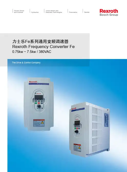
力士乐Fe系列通用变频调速器Rexroth Frequency Converter Fe 0.75kw ~ 7.5kw / 380VACThe Drive & Control Company作为一个企业,我们具有 00多年的历史传统,是德国罗伯特.博世集团的全资子公司,在传动和控制领域声誉卓著。
006年全球销售额超过49亿欧元,拥有专业员工 9,831名。
早在1978年,博世力士乐就开始了在中国的业务,现已拥有1715名优秀雇员。
凭借一流的产品和丰富的应用经验,我们为中国客户提供现代、高效和灵活的完整解决方案。
利用力士乐的电子传动与控制技术,您的自动控制易如反掌几乎没有哪个行业不能从力士乐电子传动与控制技术中获利。
从机械制造业、汽车工业、印刷与造纸工业到食品和包装工业。
一句话:谁想使他的生产过程实现高度的自动化,就不要错过力士乐。
只有通过最好的单个组件才能设计出艺术级的系统化解决方案自动控制过程变得越来越错综复杂和苛刻。
然而不管要求多高力士乐都能为您提供最合适的解决方案。
从开放的控制系统,到智能传动机构,直至深思熟虑的架构方案,都是为了工程技术的统一和用户操作方便。
一手造就一切、完美协调、技术领先遍布世界。
新的解决途径迈向更大的进步—力士乐自动控制之家未来不会眷顾每天都做重复工作的地方。
相反,只有在每天都致力于客户的需求并将其发展为具有未来能力的地方,才能产生未来的解决方案。
我们也正是这样做的,我们的自动控制之家奠定了不断进步的基础。
这个独一无二的系统百宝箱里面包含了生产电气自动化的所有组件和模块,因此可以在现代机械设备制造中实现面向未来的全新解决方案。
3博世力士乐就在您身边!4技术规格参数表5主要特征采用DSP高性能数字微处理器采用最新的IGBT大功率模块采用较高的可自动调节载波频率(1-15kHz),减少发热提高效率并降低电机运行的噪声采用印制板加厚保护层工艺,更适合恶劣的环境采用高可靠性的光电耦合器件,实现精准无误的数字输入采用冷却风扇自控技术,可实现有效节能及延长风扇寿命加装1路差动/正交编码器输入。
变频器参数设置方法
变频器参数设置方法通常有以下几个步骤:
1. 确定需要控制的电机参数:包括电机功率、额定电流、额定电压等。
2. 设置电机控制模式:可以选择速度控制模式、扭矩控制模式等,根据具体需求进行选择。
3. 设置电机额定频率:根据电机的额定电压和额定频率,设置变频器的输出频率。
通常,额定频率为电机的额定转速除以60。
4. 设置变频器的输出电压:根据电机的额定电压,设置变频器输出电压。
5. 设置变频器的过载保护参数:根据电机的额定电流,设置变频器的过载保护参数,以保护电机不受过载损坏。
6. 调整变频器的PID参数:根据实际情况,调整变频器的PID参数以达到更好的控制效果。
7. 进行试运行和调试:在设置完成后,先进行试运行,观察电机的运行情况是否正常,如有异常可对参数进行调整。
需要注意的是,变频器的参数设置方法可能因品牌和型号而有所差异,因此,在进行参数设置之前,最好查阅相关的产品说明书或咨询厂家的技术支持。
变频器功能参数设置调试变频器在出厂时对功能参数都进行了初设定,但设定的功能参数不肯定都符合某项详细的使用要求。
因此,有些功能参数要依据详细要求重新设定。
这里要特殊指出的是,变频器的功能参数有几百条,重新设定的功能参数只是依据需要才进行改动,改动的只是变频器功能参数中的一小部分,大部分与某项详细应用无关的功能参数不用改动,保留出厂设定值。
如不加推断的不修改和乱修改功能参数,都会引起故障或不必要的麻烦。
变频器使用说明书中给出的功能参数,都是可以改动和重新设置的。
但在一般工程中,常常涉及到的功能参数有:操作方法、频率、最高频率、额定电压、加/减速时间、电子热过载继电器、转矩限止、电动机极数等。
(1)加减速时间的设置在生产机械的工作过程中,加速过程(或起动过程)属于从一种运行状态转换到另一种运行状态的过渡过程,在这段时间内,通常是不进行生产活动的。
因此,从提高劳动生产率的角度动身,加速时间应越短越好。
但加速时间过短,简单因“过电流”而跳闸。
所以,预置加速时间的基本原则,就是在不发生过电流的前提下,越短越好。
通常,可先将加速时间预置得长一些,观看拖动系统在起动过程中电流的大小,如起动电流较小,可渐渐缩短加速时间,直至起动电流接近上限值时为止。
影响加速时间的因素有负载的惯性大小、负载与变频器的容量是否匹配等。
有些负载对起动和制动时间并无要求,如风机和水泵,其加、减速时间可适当地预置得长一些。
与加速过程一样,在生产机械的工作过程中,减速过程(或停机过程)也属于从一种状态转换到另一种状态的非生产过程,从提高生产率的角度动身,减速时间也应越短越好。
但如上述,减速时间过短,简单“过电压”。
所以,预置减速时间的基本原则,就是在不发生过电压的前提下,越短越好。
通常,可先将减速时间预置得长一些,观看拖动系统在停机过程中直流电压的大小,如直流电压较小,可渐渐缩短减速时间,直至直流电压接近上限值时为止。
(2)转矩提升又叫转矩补偿。
博世力士乐变频器调参数
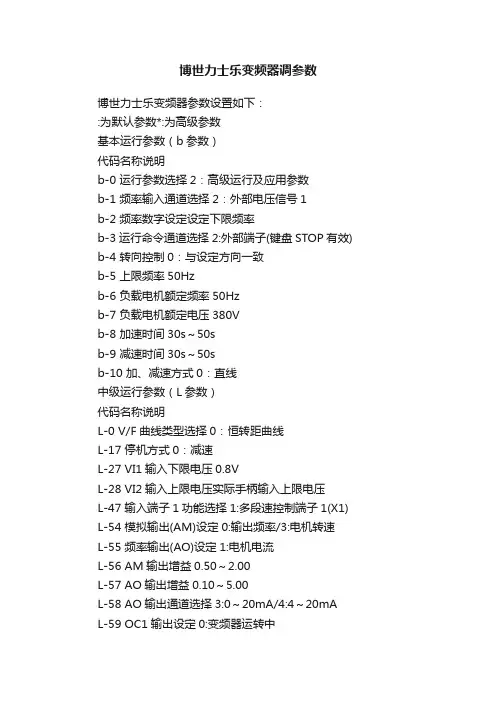
博世力士乐变频器参数设置如下:
:为默认参数*:为高级参数
基本运行参数(b参数)
代码名称说明
b-0 运行参数选择2:高级运行及应用参数
b-1 频率输入通道选择2:外部电压信号1
b-2 频率数字设定设定下限频率
b-3运行命令通道选择2:外部端子(键盘STOP有效) b-4 转向控制0:与设定方向一致
b-5 上限频率50Hz
b-6 负载电机额定频率50Hz
b-7 负载电机额定电压380V
b-8 加速时间30s~50s
b-9 减速时间30s~50s
b-10 加、减速方式0:直线
中级运行参数(L参数)
代码名称说明
L-0 V/F曲线类型选择0:恒转距曲线
L-17 停机方式0:减速
L-27 VI1输入下限电压0.8V
L-28 VI2输入上限电压实际手柄输入上限电压
L-47 输入端子1功能选择1:多段速控制端子1(X1) L-54 模拟输出(AM)设定0:输出频率/3:电机转速
L-55 频率输出(AO)设定1:电机电流
L-56 AM输出增益0.50~2.00
L-57 AO输出增益0.10~5.00
L-58 AO输出通道选择3:0~20mA/4:4~20mA
L-59 OC1输出设定0:变频器运转中
L-60 OC2输出设定23:电机反向运行中
L-61 继电器输出功能18:故障状态及过热过载限流运行中*H-14 多段数频率1 35Hz
(H-*):为高级参数。
前 言感谢您选用博世力士乐电子传动与控制(深圳)有限公司的变频调速器(以下简称变频器)!CVF - G3系列、CVF - P3系列变频器是自主开发、生产的高性能变频器,该产品采用高品质的元器件、优质材料,并融合高新微电脑控制技术制造而成。
本使用手册提供如下产品系列的操作指南:(1) CVF-G3系列通用型变频器(2) CVF-P3系列风机、水泵专用型变频器本手册阐述了用户安装配线、参数设定、故障诊断和故障排除、日常维护等相关事宜。
为确保能正确操作此系列变频器,发挥其优越性能,请在装机之前,详细阅读本使用手册,并请妥善保存,或将本手册交于该机器的使用者。
如对于本变频器的使用存在疑问或有特殊要求,请随时联络本公司的各地办事处或经销商,也可与本公司总部售后服务中心联系,我们将竭诚为您服务。
我们一直致力于产品的不断完善,故本系列变频器的相应资料(操作手册、宣传资料等)如有变动,恕不另行通知。
欢迎选用本公司其它系列变频器产品:CVF-ZS系列注塑机专用型变频器CVF-ZC系列注塑一体化柜机CVF-LS1系列拉丝机专用型变频器CVF-LY1系列络筒机/印花机专用型变频器CVF-S1 系列单相小功率变频器CVF-SMP系列简易型单相小-1-功率变频器CVF-MN1 系列迷你型单相小功率变频器CVF-V1 系列高性能矢量型变频器开箱时,请认真确认以下内容:1.产品是否有破损,零部件是否有损坏、脱落现象,主体是否有碰伤现象;2.本机铭牌所标注的额定值是否与您的订货要求一致;3.本公司在产品的制造及包装出厂方面,质量保证体系严格,但若发现有某种检验遗漏,请速与本公司或供应商联系,我们将在第一时间为您解决。
变频器型号说明:-2-目录1.注意事项...................................................11.1 安全标识定义..........................................11.2 安装注意事项..........................................11.3 使用注意事项..........................................21.4 报废注意事项..........................................42.安装与配线..............................................52.1 产品技术指标及规格.................................52.2 系列型号说明.....................................72.3 安装环境要求.................................82.4 变频器的安装尺寸...................................82.5 操作面板尺寸...................................102.6 盖板的拆卸与安装....................................112.7 操作面板的拆卸与安装................................112.8 安装方向与空间......................................122.9 变频器的配线........................................132.10 回路端子台的配线....................................212.11 JP跳线说明.........................................282.12 接线说明............................................293.操作与运行 .............................................353.1 面板操作............................................353.2 名词术语说明.......................................363.3 面板功能说明....................................393.4 键盘操作方法.....................................403.5 变频器的运行.....................................444.功能参数一览表 .........................................474.1 基本运行参数(b参数)................................474.2 中级运行参数(L参数).................................48- 3 -4.3 高级运行参数(H参数).................................514.4 状态监控参数一览表...................................554.5 保护功能及对策......................................574.6 故障记录查询........................................585.功能详细说明 ............................................605.1 基本运行参数(b参数)..................................605.2 中级运行参数(L参数).................................685.3 高级运行参数(H参数).................................836.维护与保养 ............................................976.1 日常检查与保养.......................................976.2 定期维护.............................................986.3 易损部件的检查与更换.................................996.4 存放及保修............................................99 7.使用范例.................................................1017.1 面板控制起、停, 面板电位器设置频率.....................1017.2 三线制控制模式........................................1027.3 外部控制方式、外部电压设定频率.........................1037.4 多段速运行、外部控制方式...............................1047.5 可编程多段速控制......................................1057.6 多台变频器的联动运行(群组控制) .......................1067.7 用变频器构成闭环控制系统..............................1107.8 用上位机(PC)控制多台变频器...........................111 8.选件.....................................................1138.1 远控线缆和远控适配器................................1138.2 供水附件............................................1138.3 制动组件............................................113- 4 -附录1:RS485通讯协议........................................115附录2:供水附件的应用.......................................126- 5 -- 6 -第一章 博世力士乐电子传动与控制(深圳)有限公司 注意事项为了确保您的人身、设备及财产安全,在使用变频器之前,请务必仔细阅读本章内容,并在以后的搬运、安装、运行、调试与检修过程中遵照执行。
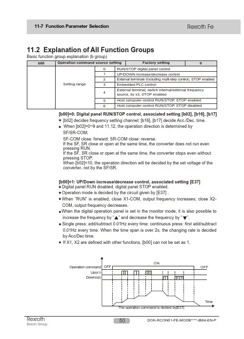
11.2 Explanation of All Function GroupsBasic function group explanation (b group)[b00]=0: Digital panel RUN/STOP control, associated setting [b02], [b16], [b17][b02] decides frequency setting channel; [b16], [b17] decide Acc./Dec. time.When [b02]=0~9 and 11,12, the operation direction is determined bySF/SR-COM;SF-COM close: forward; SR-COM close: reverse.If the SF, SR close or open at the same time, the converter does not run evenpressing RUN.If the SF, SR close or open at the same time, the converter stops even withoutpressing STOP.When [b02]=10, the operation direction will be decided by the set voltage of theconverter, not by the SF/SR.[b00]=1: UP/Down increase/decrease control, associated setting [E37]Digital panel RUN disabled, digital panel STOP enabled.Operation mode is decided by the circuit given by [E37] .When “R UN” is enabled, close X1-COM, output frequency increases; close X2-COM, output frequency decreases.increase the frequency by “” and decrease the frequency by “ ”.Single press: add/subtract 0.01Hz every time; continuous press: first add/subtract0.01Hz every time. When the time span is over 2s, the changing rate is decidedby Acc/Dec time.If X1, X2 are defined with other functions, [b00] can not be set as 1.Host Computer Control RUN/STOP and Running Direction[b00]=1, giving the initial value of the frequency, also can set the frequency directly with this function code.[b00]=2/3, is the frequency setting source of the 0-phase speed.[b00]=2: External terminals (including multi-phase terminals) control, associated [E37] setting; P-group parameters; STOP enabled.RUN disabled, STOP enabled.The source of operation mode and command are decided by the given circuit from [E37]=0,1, 2.The multi-phase speed 0~7 is selected by the binary combination of terminals X3, X2, X1-COM. The multi-phase speed holding time isdecided by the continuous combination duration of X3, X2, X1-COM; the running direction is decided by the given circuit from [E37]; frequency Acc./Dec. time is decided by P-group parameters.Press the RUN or close SF-COM to start; press the STOP or close SR-COM to stop.For the phase that has no relation to programming, set the function code of the holding time as OFF; for the phase related to programming, set the function code of holding time and the P-group parameters like the frequency, the running direction, Acc./Dec. etc.RUN disabled, STOP enabledThe operation mode is decided by the given circuit from [E37].When X3-COM is closed, the frequency is set by the external signal; the action of [b02] =0~2 is the same as [b02]=5; other values of [b02] are set normally.When X3-COM is open, the frequency is set by the potentiometer on the panel.[b00]=4: External terminal; internal/externl frequency source is switched by X3; STOP enabled; associated setting, [b02] If X1, X2, X3 are defined with other functions, [b00] can not be set as 2; The default input of the occupied terminal X is 0.[b00]=5: RUN/STOP is controlled by the host computer; STOP enabled; associated settings, [H08], [H09], [H10], [H11].The host computer controls the RUN/STOP and the running direction; STOP enabled.[b00]=6:RUN/STOP is controlled by the host computer; STOP disabled. associated settings, [H08], [H09], [H10].The host computer controls the RUN/STOP and the running direction; STOP disabled.[b00]=3: Embedded PLC control; associated setting, P-group parametersInput current 4-20mA+10V Panel potentiometer control 0-5VDC Analog voltage control 0-10VDC· [b02]=10, input the -10V~+10V analog signal by terminal VRC, at the same time, input voltage determines the running direction. When the input signal is “+”, it represents forward; otherwise it represents rever se. [b02]=5, 6, 9,10, set jumper JP5 2-3.· A-, set jumper Jp2 as 1-2.When [b02]=11, the [E25]=4/5 disabled.In this mode, set [b40] properly, making sure the [b40] setting value and the corresponding Max.Given frequency of [b30] curve.· [b02]=12, the frequency setting is determined by the host computer. In this option, please set the function codes [H08], [H09], [H10] , [H11] properly.Note: See also in Chapter 14.1, the operation and setting diagram.Setting the Max. output frequency of the frequency converter. .The rated frequency of the motor is set based on the nameplate content.The rated voltage of the load motor is set based on the nameplate content.OFF: The user-defined V/F curve mode, at the same time, shows the hidden function code [b07]~[b13].It is the Min. frequency that motor allows. This function sets the Min. frequency of user-defined V/F curve.It is the Min. voltage that motor allows. It is a percentage of the base voltage. This function sets the Min.voltage of the user-defined V/F curve.The middle frequency 1 of the user-defined V/F curve.The corresponding voltage of the middle frequency 1 (Mf1) of the user-defined V/F curve, is a percentageThe middle frequency 2 of the user-defined V/F curve.The corresponding voltage of the middle frequency 2 (Mf2) of the user defined V/F curve.The corresponding voltage of the highest frequency (HF) of the user-defined V/F curve, range: 0~120%BV.· automatically the V/F output voltage at the set value even the voltage of the power supply which connects to the input of the frequency converter varies.It has to be mentioned that the output voltag e can not be hig her that the input voltag e of the frequency converter even the constant voltage control is on.When this parameter is set OFF, the constant voltage control function is disabled and the output voltage will be proportional to the input voltage.General V/F curve settings are as follows:(a) General applicationH-0~H-15 constant torque characteristicP-00~P-15 square rate decreased torqueParameter setting description of fan and pump typesH curve, P curve voltage(C) User-defined V/F curve[b06]=oFF, can be defined the following V/Fcurve by [b03]- [b05], [b07]~[b13].[b13] HV [b05] BV [b08] LLV[b07][b09][b04][b11][b03]According to the requirements of the load motor, the following common use V/F curves are available.BVMF1MF2MF2BVMV1LLVConstant torque curveFan, pump energy saving curve MF2BVLLV MV MF1MF2BVHV High startup torque curveVariable frequency motor with increased voltage, higher than the frequency requirement[b15] Acc./Dec. curve modeAcc timeDec timeAcc timeDec timeThe selection of b15 also decides the curve mode of JOG Acc./Dec.[b16] Acceleration timeWhen the programmable mode is disabled (b 3), it represents the output frequency increasing time from 0.00Hz to HF .When the programmable mode is enabled (b=3) and the operation is under multi-phase 0, it represents the output frequency increasing time from 0.00Hz to the frequency command [b01].[b17] Deceleration timeWhen the programmable mode is disabled (b 3), it represents the output frequency decreasing time from HF to 0.00Hz.When the programmable mode is enabled (b=3) and the operation is under multi-phase 0, it represents the output frequency decreasing time from the frequency command [b01] to 0.00Hz. (1) Programmable operation disabled ([b00]3)· This parameter is used to set the delay time between the deceleration, stop and the start of reversed acceleration when the motor rotating speed changes. The parameter should be set according to load inertia, and Acc./Dec. time.(2) Programmable operation enabled ([b00] =3)TimeOutput frequency· When the forward and reverse signals are input simultaneously, the motor will decelerate and stop. When “0.0s” is set, the reverse operation is forbidden and only the forward operation is allowed.Output frequencyReversedForward· Electronic thermal relay setting value (%)=(motor rated current /frequency converter rated current) ×100%. When single motor is connected to single converter, overload relay needs not to be connected externally, and set the parameter according to motor characteristic.· When driving several motors or motor rated current is lower than the set value Et, the motor is not protected actively. In that case, please equip each motor with thermal protection relay.· As the figure of overload protection reverse time-limit shows, for general series: 150% rated current for 1 minute, 110% rated current for 1 hour.· If it is not set as OFF, the range is “50~110%”.frequency and over excitation of the motor can also be avoided while it is running without load.In the real operation, the voltage increase percentage is decided by the frequency converter based on the present output frequency and the load current.[b19] should be increased step by step. Too big value of the parameter may cause over current ofthe motor or enable the Auto Current Limit function. If it is not set as “oFF”, the setting range is “1~10%”. · When “oFF” is set effective, the automatic torque increase function is disabled; when other values are set, the values are the percentag e of the increased voltag e at 0 output frequency, rated current. This parameter is to improve the torque characteristic when the motor is running at low frequency. With that function, the output voltag e of the frequency converter can be adjusted· UF is the Max. frequency which the frequency converter outputs during steady running.· LF is the Min. frequency which the frequency converters outputs during steady running.· When the input frequency command is lower than the set value of the lower limit frequency (LF), the frequency converter has two working modes:[b23]=0, the output frequency is decreased directly from the lower limit frequency to 0.00Hz; the hysteresis frequency width needs to be set in order to prevent frequency converter from the frequency RUN/STOP around the lower limit frequency.[b23]=1, the frequency converter is kept running at the lower limit frequency.General series[b26] defines the time constant of the first inertia to conduct the first inertia filter of the analoginput reference sig nal. The big g er the time constant, the more obvious the restraining effect, but the slower the response. [b26] is also the filter time constant of FB channel.Reference frequency signal is filtered and amplified, and then its relationship with the set frequency is determined by the Curve (defined by [b27]~[b30]), which is shown in the right hand figure.compensation, and decrease the slip so that the motor can run at the rated current and the speed is close to the synchronous speed. Consumer will set slip frequency compensation according to load. Customers can use the slip frequency compensation according to the load situation.Note: when using the slip frequency compensation, [H35]must be disabled, [H35]=0.00.Note: If the compensation is set too big, the motorspeed will exceed the synchronous speed. In this case: Upper limit frequency=output frequency + K ×slipfrequency [b31].K is associated with load current and is not bigger than 1.· The relationship between frequency source and frequency setting is shown in the next figure, when VRC,+I pulse or panel potentiometer are set as open-loop frequency setting channels.· Using analog signal (0~5V, 0~10V, 4~20mA, panel potentiometer 0~5V) and pulse frequency to set frequency, outputfrequency can be set freely by setting [b25] and [b27], [b 28],[b29], [b30].The motor has two stop modes: Deceleration stop and inertia slide stop.[b34]=0: Inertia stop disabled, deceleration stop active.[b34]=1~3: external terminals X1,X2 or X3-COM are closed to realize inertia slip stop with. When other stop orders are set, deceleration stop is active.[b34]=4: inertia slide stop.If the setting is 1~3, when the selected terminal and the COM terminal are closed during operation,the converter will be stopped in inertia stop mode immediately and F.r .on will be displayed at the same time as the external terminals are closed. Once the terminals and COM are open, the output accelerates again from 0.00H to the set frequency. If there is stop signal, but the selected terminal and the COM open, then the motor decelerates to stop. If X1, X2 or X3 have alreadybeen defined with other functions, then the [b34] does not show the corresponding parameter in order to avoid repeated definition ofterminals.[b32] This function could regulate starting torque characteristic with torque compensation, but if the setvalue is too big, over current may happen.[b33] Start up hold time is the running holding time with the start up frequency.If the running frequency is lower than start up frequency, the output frequency is the start up frequency.After the holding time of the start up frequency, the output frequency will be decreased to the running· [b35]=0: Cannot carry on the Jog operation.· [b35]=1~3: Selection terminals X1~X3 as the jog operation signal input terminals, close is enabled. When the jog operation signal and the operation signal are enabled at the same time, then the jog operation is effective.Jog operation is forbidden in the programmable mode.Jog operation acceleration time[b37] is time for frequency increase from 0.00Hz to HF. Jog operation deceleration time [b38] is time for frequency decrease from HF to 0.00Hz.When the Jog operation stops, if the jog operation frequency is higher than the set operation frequency, then decrease the frequency to the set frequency according to the Jog deceleration time.If the Jog frequency is lower than the operation frequency, then increase the frequency to the set frequency according to the normal acceleration time. Three common modes of Jog.· When [b02]=11, this functional code provides [b30] value corresponding to external input pulse frequency. (200.0kHz).· When [b02]=11, [E24]=0, [E25]=4 or 5 (PI control), this functional code provides the biggest engineering value corresponding to feedback pulse frequency.The jog operation at the operation frequency as 0.00HzAccelerate frequency increase speed by jog operationThe jog operation at frequency lower than the operation frequency· When [b00]=0, [b02]=0 or [b00]=1 or [b00]=2, [b02]=0, if [b42]=1, then the present set frequency will be saved in function code [b01] before the system power is off. After the power is on nextExtended function group description (E group )This function is used to prevent from load mechanic vibration (noise) and resonance etc; Three skip frequencies can be set in the range of 0.00Hz-HF;Set the range of skip frequency to 0.00Hz when the skip frequency function is not used;This function is inactive during acceleration and deceleration;The function is suitable for any frequency setting selected by [b02].· A 0~20mA DC ammeter or a 0~10V DC voltmeter can be connected between FM1 or FM2 and GND to monitor the inverter output frequency, output voltage or output current.· When 2-3 of JP3 is shorted, the output of FM2 is 0-10V, please connect the voltmeter or cymometer with full range of 10V and impedance of 10K .· When 1~2 of JP4 is shorted, the output of FM1 is 0~20mA, please connect the ammeter or frequency indicator with the full range of 20mA.[E04]=0: output frequency, when the output reaches HF, terminal FM1 outputs 20mA or 10V; [E04]=1: output voltage, when the output reaches AC 500V, terminal FM1 outputs 20mA or 10V;[E04]=2: output current, when the output reaches 2 times of rated current, terminal FM1 outputs 20mA or 10V;[E04]=3: PI feed-back signal [E05] adjusts the FM gain.· When 2~3 of JP3 is shorted, FM2 outputs 0~10v; when 1~2 of JP3 is shorted, FM2 outputs 0~20mA. The output and gain of FM2 are selected by [E06] and [E07] respectively.20mA· DO pulse frequency output range: 0 ~ [E10].[E09] =0 output frequency, when the output reaches HF, DO outputs [E10] kHz.[E09] =1 output voltage, when the output reaches 500V, DO outputs [E10] kHz.[E09] =2 output current, when the output reaches rated current, DO outputs ([E10]/2) kHz.When output frequency exceeds [E11], the digital output “Frequency level detection 1” (FDT1) is active till the output frequency is less than the frequency set by [E11]-[E12].When output frequency exceeds [E13], the digital output “Frequency level detection 2” (FDT2) isactive till the output frequency is less than the frequency set by [E13]-[E14].Frequency arrival detectionOutput frequencyFrequency leveldetection FDT1/2Delay frequencyTimeFrequency leveldetection FDT1/2TimearrivalE1612345678910111213141516171819202122232425RunFDT1FDT2FARReservedUnder voltageOver loadReserved0 speed(less than starting frequency)EMSLower voltageAuto current limit actionFaultProgramable program operationProgramable program operation overOne phase operation overOCOVForwardReverse0 speed (including stop)BrakingAccelerationDecelerationFan activeReservedOpen collectoroutputOUT1Open collectoroutputOUT2Relay RyoutputSelectionE17 E18SettingrangeFactory settingFactory settingFactory setting612Power supply[E16], [E17], [E18] setting description:0: RunWhen the frequency converter has output, OUT or Ry is active.1: FDT1When the output frequency is higher than frequency level [E11], OUT or Ry is active till the output frequency is less than the frequency set by [E11]-[E12].2: FDT2When the output frequency is higher than frequency level [E13], OUT or Ry is active till the output frequency is less than the frequency set by [E13]-[E14].3: FARWhen the output frequency is in the range of ±[E15], OUT or Ry is active.4: Reserved5: Under voltageWhen the frequency converter detects the input voltage is too low, OUT or Ry is active.6: Over load (OL)When the frequency converter detects overload, OUT or Ry is active.7: Reserved8: Output frequency 0 speed (less than starting frequency)When the output frequency of the frequency converter is lower than the operation frequency [b32], OUT or Ry is active.9: EMSWhen the terminal EMS is closed and [E32]=0, [E33]=1, OUT or Ry is active.10: Lower voltage (BUS voltage is lower than 90% of rated voltage)When the frequency converter detects the DC bus voltag e is lower than 90% of the rated value, OUT or Ry is active.11: Auto current limit function is active.When the auto current limit function is active, OUT or Ry is active.12: FaultWhen the frequency converter detects fault, OUT or Ry is active.13: Programable program in operation ([b00]=3)When the programable program of the frequency converter is in auto operation, OUT or Ry is active. 14: Programable program operation ([b00]=3) is completed.When the programable program auto operation of the frequency converter ([b00]=3) is completed, OUT or Ry is active.15: One phase of the programable program operation ([b00]=3) is completed.When the programable ([b00]=3) is in auto operation, OUT or Ry active time is 0.5 secretary. For each phase.16: Over currentWhen the frequency converter is under over current protection at the steady state stall or the acceleration stall, OUT or Ry is active; associated parameters, [E19] and [E20].17: Over voltage stallWhen the frequency converter is under over-voltage stall protection, OUT or Ry is active; associated parameter, [H25].18: ForwardWhen the frequency converter operates forward, OUT or Ry is active.19: ReverseWhen the frequency converter operates reverse, OUT or Ry is active.20: 0 speed (including stop)21: BrakingWhen the output frequency is less than the starting frequency setting [b32] and stops, OUT or Ry is active.22: AccelerationWhen the output frequency of the frequency converter is in acceleration, OUT or Ry is active.23: DecelerationWhen inverter output frequency is in deceleration, OUT or Ry action24: Fan actionWhen the inverter's fan is in work, OUT or Ry actionThe stall OC prevention level during acceleration [E20] can be set between 50~200% of the rated current of the frequency converter. When oFF is set, this function is inactive.Shown as the figure below, the frequency stops increasing once the output current is higher than the stall OC level [E20] during acceleration; the frequency will continue increasing if the output current decreases, in this way, the stall OC is prevented. As a result, this makes the actual Acc. time longer than the set value.Note: The disabled, [H33]=OFF. If the non-trip control [H33]=ON, then set [E19]=OFF , [E20]=OFF.Output frequencyOutput currentShown as the figure below, when running under the set frequency , once the current is higher than the stall OC level, the frequency converter will decrease the output frequency automatically to control the output current below the stall OC level.The stall OC prevention level [E19] can be set between 50~200% of the rated current of the frequency converter. If oFF is set, this function is inactive· The first function of display coefficients A and B is to transform the output frequency of thefrequency converter to the corresponding value of physical variable in engineering application, which will be shown on the digital panel.In the d group of the digital panel, “oUtF”=output frequency *A+B “SEtF”= set frequency *A+BIf [E22], and [E23] are as default, “oUtF” and “SEtF” show the actual output frequency and set frequency respectively.The second function of coefficient A and coefficient B is to display the given and the feedback variables when PI function embedded in the frequency converter is selected to control the motor with close-loop.Coefficient A [E22]: Corresponding value of physical variable in engineering application to the Max. analog given or feedback variable (e.g.:5V).Coefficient B [E23]: Min. analog giving or feedback (e.g.: 0V) corresponding to project physical quantity· The PI function embedded in the frequency converter detects the sensor feedback of the control object, and compare it with the given value. If difference exists, it will be reduced to or to be 0 by the PI adjustment function. This function applies to flow, pressure, temperature, rotatingl speed controls, etc.· PI mode selection, [E24]=0: PI is not selected; 1: Forward; 2: ReverseThis function can select the forward or the revere action of the PI adjustment output, therefore the motor rotating speed can be increased or decreased according to the PI adjustment output. can cause .[E25]=5· Setting range of proportional gain [E26]: 0.00~99.99 timesThe bigger the proportional gain, the faster the response, the easier oscillation may occur.Setting range of integral time constant [E27]: 0.10~60.0s.The bigger the integral time constant, the slower the response; and the less capability to control the external disturbance, but the better the stability.The smaller the integral time constant, the faster the response, the smaller the oscillation.Only using proportional adjustment, deviation can not be eliminated. PI control is used toremove the steady state deviation in the close loop system. If the integral time constant is too big, the response to the fast changing deviation will be slow. The P adjustment can be used alone for the load system with internal component.· Simplified adjustment method of PI parameters:(1) [E26] (P)- increase value in the case of no oscillation.(2) [E27] (I)- reduce value in the case of no oscillation.[E25]=0, 1[E25]=2, 3[E25]=4[E25]=5· [E37]=2, the terminal X selected by [E30] combined with the input by the SF or SR, the self-holding is effective.[E30]=0: “Self-holding selection” is disabled.[E32]=0: Inertia sliding stop is also called free wheel stop. Alarm output selection is allowed.[E33]=0: is the non alarm state. In the valid duration of EMS input, the band brake and other machinery may be used in coordination. The display of “EMS” will disappear after awhile.[E33]=1: is the alarm state, the stop command when external abnormality exists. “EMS” will be displayed all the time till fault reset or STOP reset and then the frequency is allowed tobe operated again. The alarm signal can be output by OUT/Ry when setting [E16]=9,[E17]=9, [E18]=9.[E32]=1: Decelerates to stop according to the present set deceleration time without “EMS”displayed. The alarm state is not allowed to be set, which is invalid even[E32] =1.The low voltage protection is a kind of fault prevention measure when the voltage of the power supply is lower than 10% of the rated voltage. The motor will work based on the different setting of [ E34 ].The under voltage protection is when the voltage of the power supply is lower than 20% of the rated voltage, the frequency converter will block the output immediately and the motor will do the free wheel stop with P.OFF displayed.If [ E35 ] =1, the alarm state will be displayed till the voltage of the power supply increases up to 90% of the rated voltage, then the alarm state will be reset.The alarm signal can be output by OUT1, OUT2, when setting [E16]=5, [E17]=5, [E18]=5.[E37]=1,Operation on/stop, reverse/forward mode SF-COM close: operation SF-COM open: stop SR-COM close: reverse SR-COM open: forward[E 37]=2, With auto-protection function to the button operation [E30] selects one of X1, X2, X3 as the stop terminal SF-COM close: forwardSR-COM close: reverse X1~X3-COM open: stopWhen the frequency converter is under the forward (reverse) operation, press the reverse[E37]=1SRCOMSFforward/stopreverse action/stop[E37]=0, Forward/stop, reverse/stop modeSF-COM close: forward SR-COM close: reverse SF, SR close or open at the same time: stopWhen the operation is controlled by the digital panel ([b00]=0/3) and without stop signal, if[E36]=1, the frequency converter will start automatically without pressing RUN after the power is on; if [E36]=0, press RUN to start the frequency converter.When other operation commands are selected, if [E36]=1, the frequency converter will start immediately when there is an operation command (e.g., SF-COM close) after the power is on; if [E36]=0, even there is an operation command when power is on, the frequency converter will not start. The operation command has to be cancelled and set again (SF-COM “OPEN”and “Close” again).· [E39] is the fault retry waiting time of the frequency converter after the fault appears and [E38] is set effective ([E38] is not 0).· [E40] is the Max. allowed retry times of the frequency converter after power is on.[E45] setting the upper coefficient for close loopPI adjustment[E46] setting the lower coefficient for close loop PI adjust.In the PI adjustment process, shown as the chart: when the feedback>=Feedback upper limit (t1 point), it exits PI, reduces the output frequency according to Dec. time to the lower limit ([b23]=1) or 0.00Hz ([b23]=0);when feedback<lower (t2 point), it will be in PI process again.Feedback upper value=[E22][E45]/100Feedback lower value=[E22][E46]/100/。
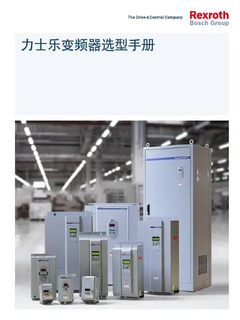
力士乐变频器选型手册2目录公司介绍 3我们的目标 4产品简介 5EFC 3600变频器 6Fe变频器 10Fb变频器 14Fv变频器 18附件选配参考 23服务及支持 313公司介绍博世力士乐(西安)电子传动与控制有限公司是德国博世集团的全资子公司,致力于在中国工控传动领域的发展,以变频器作为主营业务,以在德国和中国共同建立的实力强大的研发团队作为基础,同时凭借先进的技术、科学的管理以及优秀的员工队伍,屡创佳绩。
力士乐全系列变频器,凝聚中德技术精髓,满足不同细分市场的客户需求,能最大限度满足各种应用场合,使客户成功地逾越技术隔阂,获得最佳解决方案。
作为国内外众多优秀机械和系统制造商的合作伙伴,提供卓越的全方位的售后服务和技术支持也进一步巩固了博世力士乐在全球范围的领先地位。
这一切既给予我们鼓舞,也赋予我们责任。
博世力士乐,The Drive & Control Company,独一无二。
4我们的目标:成为全球市场的领导型企业,积极服务于客户的利益凭借着广泛的产品与服务系列,我们能够快速、灵活地响应用户的各种要求从产品开发和生产,直至销售和技术服务。
我们时刻与用户紧密合作,力求实现每一项应用系统的最佳解决方案。
正是通过我们的产品和专业技术人员,我们让用户获得决定性的竞争优势,同时确保最小的技术投入和经济负担。
纵观全球市场,作为电子传动与控制整体解决方案的专业服务提供商,在保持技术领先的同时,我们还不断迎接各种新的挑战;在世界80多个国家,公司拥有大约35,000名员工。
这一切,都要归功于公司在规划基础架构时,始终牢记贴近合作伙伴和客户实际需要的经营宗旨。
博世力士乐有着200多年的悠久历史和传统。
作为Robert Bosch GmbH 的一家全资子公司,我们已成为活跃于世界各地的这家力士乐为用户提供传动、控制与运动技术领域所需要的全套产品和服务: f 电子传动与控制 f 工业液压 f 行走机械液压 f 线性技术 f 组装技术 f 气动技术技术集团的一部分。
变频器设置参数怎么调?答:想一想当年学习变频器都是认真拜师学艺的,不像现在在网络平台上要求别人回答,而现在今日头条少得可怜的几十角钱,来买他人的技术,真是无语。
冰冻三尺非一日之寒,对于初次接触变频器的入门者来说,使用面板调节非常得心应手,但它都是出厂设置好了的,如果是要使用外部接线端子,那么就要重新设置变频器与驳接的电动机的一些参数了。
一、变频器可设置的参数♣变频器参数的设置非常重要。
变频调速系统是否能满足生产工艺要求的需要,按期望的要求运行,决定于参数的正确设置。
变频器参数设置不当会造成启动、制动的失败,误跳闸,严重时会造成变频器内部电子元器件的损坏。
变频器的参数值很多,少则五六十个,多则百余个。
对于初次接触变频器者,一定要有变频器的使用说明书,没有使用说明书,犹如盲人摸象,一筹莫展。
但变频器大多数参数不需要用户设置,按照出厂时设置值使用即可。
需要重新设置的参数主要有:基本频率、最高频率、上限频率、下限频率、U / f线,启动频率、加速度时间、减速时间、制动时间(及方式)。
此外还包括外部端子操作、模拟量操作等。
电动机的基本信息如额定电压、额定电流、额定容量、极对数、加减速时间等准确录入,是保证变频器稳定运行的前提。
例如,电动机极数设定不准确,则变频器显示转速不准确,将影响操作人员的操作。
保护参数设定是电动机发生故障时报警还是跳闸,为变频器的安全运行提供了故障。
保护参数设定包括热电子保护、过电流保护、载波保护过电压保护和失速保护等设定。
♠如果变频器保护定值设定过小,将会造成变频器频繁误动作影响电动机运行。
另外,如果加速度时间、减速度时间设定不当,则会造成变频器在加、减速时发生过电压保护动作。
变频器参数初步设定后,还要根据系统实际运行情况,对不合适的部分参数进行调整。
变频器的参数设定均有一定的选择范围,设定前应详细阅读产品说明书,掌握变频器的技术性能和设定方法。
不同品牌的变频器,其参数设定方法是不同的,要看它们的功能及代码、参数名称、设置范围和出厂值。
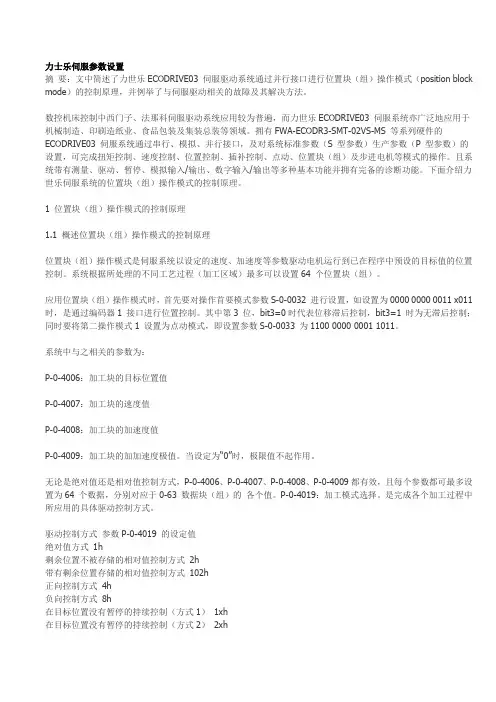
力士乐伺服参数设置摘要:文中简述了力世乐ECODRIVE03 伺服驱动系统通过并行接口进行位置块(组)操作模式(position block mode)的控制原理,并例举了与伺服驱动相关的故障及其解决方法。
数控机床控制中西门子、法那科伺服驱动系统应用较为普遍,而力世乐ECODRIVE03 伺服系统亦广泛地应用于机械制造、印刷造纸业、食品包装及集装总装等领域。
拥有FWA-ECODR3-SMT-02VS-MS 等系列硬件的ECODRIVE03 伺服系统通过串行、模拟、并行接口,及对系统标准参数(S 型参数)生产参数(P 型参数)的设置,可完成扭矩控制、速度控制、位置控制、插补控制、点动、位置块(组)及步进电机等模式的操作。
且系统带有测量、驱动、暂停、模拟输入/输出、数字输入/输出等多种基本功能并拥有完备的诊断功能。
下面介绍力世乐伺服系统的位置块(组)操作模式的控制原理。
1 位置块(组)操作模式的控制原理1.1 概述位置块(组)操作模式的控制原理位置块(组)操作模式是伺服系统以设定的速度、加速度等参数驱动电机运行到已在程序中预设的目标值的位置控制。
系统根据所处理的不同工艺过程(加工区域)最多可以设置64 个位置块(组)。
应用位置块(组)操作模式时,首先要对操作首要模式参数S-0-0032 进行设置,如设置为0000 0000 0011 х011 时,是通过编码器1 接口进行位置控制。
其中第3 位,bit3=0时代表位移滞后控制,bit3=1 时为无滞后控制;同时要将第二操作模式1 设置为点动模式,即设置参数S-0-0033 为1100 0000 0001 1011。
系统中与之相关的参数为:P-0-4006:加工块的目标位置值P-0-4007:加工块的速度值P-0-4008:加工块的加速度值P-0-4009:加工块的加加速度极值。
当设定为“0”时,极限值不起作用。
无论是绝对值还是相对值控制方式,P-0-4006、P-0-4007、P-0-4008、P-0-4009都有效,且每个参数都可最多设置为64 个数据,分别对应于0-63 数据块(组)的各个值。

The Drive & Control Company变频器EFC 3610 / EFC 5610系列快速启动指南版本11R912005855Bosch Rexroth AG EFC 3610 / EFC 5610更改过程出版颁发日期备注DOK-RCON03-EFC-X610***-QU01-ZH-P2014.09试用版本DOK-RCON03-EFC-X610***-QU02-ZH-P2014.11增加了新功能DOK-RCON03-EFC-X610***-QU03-ZH-P2015.01增加了新功能DOK-RCON03-EFC-X610***-QU04-ZH-P2015.04增加了新功能DOK-RCON03-EFC-X610***-QU05-ZH-P2015.07增加了新功能DOK-RCON03-EFC-X610***-QU06-ZH-P2015.10增加了新功能DOK-RCON03-EFC-X610***-QU07-ZH-P2016.03增加了新功能DOK-RCON03-EFC-X610***-QU08-ZH-P2016.06增加了新功能DOK-RCON03-EFC-X610***-QU09-ZH-P2017.01增加了新功能DOK-RCON03-EFC-X610***-QU10-ZH-P2017.04增加冷板机型DOK-RCON03-EFC-X610***-QU11-ZH-P2017.06增加了新功能关于此文档该《快速启动指南》基于产品《使用手册》, 《使用手册》包含产品的详细数据。
不当应用、安装或操作可能导致人身伤害或财产损失!在未通读以下文档前, 请勿操作该产品●标准发货附带的《安全说明》●《使用手册》中的安全说明信息参考文档如需其他类型或语言的文档, 请联系当地代理商或访问以下网址:/efcx610版权© 博世力士乐(西安)电子传动与控制有限公司 2017该文档以及其中的数据、技术规格和其它信息均为博世力士乐(西安)电子传动与控制有限公司的专有财产。
力士乐REXROTH伺服参数设置文中简述了力世乐ECODRIVE03 伺服驱动系统通过并行接口进行位置块(组)操作模式(position block mode)的控制原理,并例举了与伺服驱动相关的故障及其解决方法。
数控机床控制中西门子、法那科伺服驱动系统应用较为普遍,而力世乐ECODRIVE03 伺服系统亦广泛地应用于机械制造、印刷造纸业、食品包装及集装总装等领域。
拥有FWA-ECODR3-SMT-02VS-MS 等系列硬件的ECODRIVE03 伺服系统通过串行、模拟、并行接口,及对系统标准参数(S 型参数)生产参数(P 型参数)的设置,可完成扭矩控制、速度控制、位置控制、插补控制、点动、位置块(组)及步进电机等模式的操作。
且系统带有测量、驱动、暂停、模拟输入/输出、数字输入/输出等多种基本功能并拥有完备的诊断功能。
下面介绍力世乐伺服系统的位置块(组)操作模式的控制原理。
1 位置块(组)操作模式的控制原理1.1 概述位置块(组)操作模式的控制原理位置块(组)操作模式是伺服系统以设定的速度、加速度等参数驱动电机运行到已在程序中预设的目标值的位置控制。
系统根据所处理的不同工艺过程(加工区域)最多可以设置64 个位置块(组)。
应用位置块(组)操作模式时,首先要对操作首要模式参数S-0-0032 进行设置,如设置为0000 0000 0011 х011 时,是通过编码器1 接口进行位置控制。
其中第3 位,bit3=0时代表位移滞后控制,bit3=1 时为无滞后控制;同时要将第二操作模式1 设置为点动模式,即设置参数S-0-0033 为1100 0000 0001 1011。
系统中与之相关的参数为:P-0-4006:加工块的目标位置值P-0-4007:加工块的速度值P-0-4008:加工块的加速度值P-0-4009:加工块的加加速度极值。
当设定为“0"时,极限值不起作用。
无论是绝对值还是相对值控制方式,P-0-4006、P-0-4007、P-0-4008、P-0-4009都有效,且每个参数都可最多设置为64 个数据,分别对应于0-63 数据块(组)的各个值。
前 言感谢您选用博世力士乐电子传动与控制(深圳)有限公司的变频调速器(以下简称变频器)!CVF - G3系列、CVF - P3系列变频器是自主开发、生产的高性能变频器,该产品采用高品质的元器件、优质材料,并融合高新微电脑控制技术制造而成。
本使用手册提供如下产品系列的操作指南:(1) CVF-G3系列通用型变频器(2) CVF-P3系列风机、水泵专用型变频器本手册阐述了用户安装配线、参数设定、故障诊断和故障排除、日常维护等相关事宜。
为确保能正确操作此系列变频器,发挥其优越性能,请在装机之前,详细阅读本使用手册,并请妥善保存,或将本手册交于该机器的使用者。
如对于本变频器的使用存在疑问或有特殊要求,请随时联络本公司的各地办事处或经销商,也可与本公司总部售后服务中心联系,我们将竭诚为您服务。
我们一直致力于产品的不断完善,故本系列变频器的相应资料(操作手册、宣传资料等)如有变动,恕不另行通知。
欢迎选用本公司其它系列变频器产品:CVF-ZS系列注塑机专用型变频器CVF-ZC系列注塑一体化柜机CVF-LS1系列拉丝机专用型变频器CVF-LY1系列络筒机/印花机专用型变频器CVF-S1 系列单相小功率变频器CVF-SMP系列简易型单相小-1-功率变频器CVF-MN1 系列迷你型单相小功率变频器CVF-V1 系列高性能矢量型变频器开箱时,请认真确认以下内容:1.产品是否有破损,零部件是否有损坏、脱落现象,主体是否有碰伤现象;2.本机铭牌所标注的额定值是否与您的订货要求一致;3.本公司在产品的制造及包装出厂方面,质量保证体系严格,但若发现有某种检验遗漏,请速与本公司或供应商联系,我们将在第一时间为您解决。
变频器型号说明:-2-目录1.注意事项...................................................11.1 安全标识定义..........................................11.2 安装注意事项..........................................11.3 使用注意事项..........................................21.4 报废注意事项..........................................42.安装与配线..............................................52.1 产品技术指标及规格.................................52.2 系列型号说明.....................................72.3 安装环境要求.................................82.4 变频器的安装尺寸...................................82.5 操作面板尺寸...................................102.6 盖板的拆卸与安装....................................112.7 操作面板的拆卸与安装................................112.8 安装方向与空间......................................122.9 变频器的配线........................................132.10 回路端子台的配线....................................212.11 JP跳线说明.........................................282.12 接线说明............................................293.操作与运行 .............................................353.1 面板操作............................................353.2 名词术语说明.......................................363.3 面板功能说明....................................393.4 键盘操作方法.....................................403.5 变频器的运行.....................................444.功能参数一览表 .........................................474.1 基本运行参数(b参数)................................474.2 中级运行参数(L参数).................................48- 3 -4.3 高级运行参数(H参数).................................514.4 状态监控参数一览表...................................554.5 保护功能及对策......................................574.6 故障记录查询........................................585.功能详细说明 ............................................605.1 基本运行参数(b参数)..................................605.2 中级运行参数(L参数).................................685.3 高级运行参数(H参数).................................836.维护与保养 ............................................976.1 日常检查与保养.......................................976.2 定期维护.............................................986.3 易损部件的检查与更换.................................996.4 存放及保修............................................99 7.使用范例.................................................1017.1 面板控制起、停, 面板电位器设置频率.....................1017.2 三线制控制模式........................................1027.3 外部控制方式、外部电压设定频率.........................1037.4 多段速运行、外部控制方式...............................1047.5 可编程多段速控制......................................1057.6 多台变频器的联动运行(群组控制) .......................1067.7 用变频器构成闭环控制系统..............................1107.8 用上位机(PC)控制多台变频器...........................111 8.选件.....................................................1138.1 远控线缆和远控适配器................................1138.2 供水附件............................................1138.3 制动组件............................................113- 4 -附录1:RS485通讯协议........................................115附录2:供水附件的应用.......................................126- 5 -- 6 -第一章 博世力士乐电子传动与控制(深圳)有限公司 注意事项为了确保您的人身、设备及财产安全,在使用变频器之前,请务必仔细阅读本章内容,并在以后的搬运、安装、运行、调试与检修过程中遵照执行。
Bosch Rexroth AG目录目录页数1 使用手册简介 (1)2 电气传动和控制设备的安全说明 (2)2.1 术语定义 (2)2.2 警示词和安全提示符号说明 (3)2.3 总则 (4)2.3.1 安全说明的使用和传递 (4)2.3.2 安全使用要求 (4)2.3.3 使用不当引发的危险 (5)2.4 针对特殊危险的说明 (5)2.4.1 与电气元件和外壳接触的防护 (5)2.4.2 保护性特低压防止电击 (6)2.4.3 危险动作的防护 (6)2.4.4 在操作和安装期间对磁场和电磁场的防护 (7)2.4.5 与高温部件接触的防护 (7)2.4.6 搬运与安装时的防护 (8)3 重要的使用说明 (9)3.1 正确的使用 (9)3.2 不正确的使用 (9)4 供货与保存 (10)4.1 产品识别 (10)4.1.1 检查外包装箱铭牌信息 (10)4.1.2 检查机身铭牌信息 (11)4.1.3 检查机器外观 (11)4.2 供货范围 (12)4.3 设备的运输 (13)4.4 设备的存放 (13)5 安装与配线 (14)5.1 EFC 3600变频器外型 (14)5.2 EFC 3600尺寸 (16)5.3 EFC 3600安装 (17)5.4 标准配线图 (20)5.5 主回路配线注意事项 (21)5.6 主回路基本配线图 (22)Bosch Rexroth AG目录页数5.7 主回路端子 (23)5.8 主回路端子说明 (23)5.9 熔断器和电缆规格 (24)5.9.1 选择标准 (24)5.9.2 推荐电缆规格 (25)5.9.3 熔断器设计推荐 (26)5.10 主回路配线步骤 (26)5.11 内置EMC滤波器接地螺钉的移除 (27)5.12 控制回路配线注意事项 (28)5.13 控制回路端子 (28)5.14 控制回路端子说明 (29)5.15 数字输入NPN/PNP开关SW (30)5.16 NPN/PNP模式 (31)5.17 模拟输入端子(+10V, Vr1, GND, +I) (32)5.18 控制回路配线推荐 (32)5.19 控制回路配线步骤 (33)6 操作面板 (34)6.1 操作面板图示及说明 (34)6.2 数码管显示 (34)6.3 LED指示灯 (35)6.4 菜单结构 (36)6.5 操作方式说明 (37)6.6 操作示例 (37)7 试运行 (38)7.1 试运行前的检查和准备 (38)7.2 试运行过程 (39)7.3 基本运行参数快捷设定 (40)7.4 恢复为出厂参数 (41)7.5 试运行中简单故障的对策 (41)8 参数设置 (42)8.1 b0组:系统参数 (42)8.1.1 密码及访问控制参数 (42)8.1.2 系统配置参数 (44)8.1.3 变频器配置参数 (45)8.1.4 监视显示参数 (46)8.1.5 系统信息参数 (48)Bosch Rexroth AG目录页数8.2 b1组:基本参数 (49)8.2.1 基本运行控制参数 (49)8.2.2 加/减速控制参数 (55)8.2.3 起动配置参数 (57)8.2.4 停机配置参数 (60)8.3 S0组:V/F控制参数 (63)8.3.1 V/F曲线参数 (63)8.3.2 增强V/F控制参数 (66)8.3.3 无跳闸控制参数 (70)8.4 S2组:电机参数 (72)8.4.1 电机铭牌参数 (72)8.4.2 电机物理数据参数 (73)8.4.3 电机热保护参数 (74)8.5 S3组:运行参数 (76)8.5.1 点动参数 (76)8.5.2 跳跃频率参数 (77)8.5.3 掉电再起动参数 (78)8.5.4 制动斩波器控制参数 (79)8.5.5 其它运行控制参数 (80)8.6 E0组:输入端子参数 (82)8.6.1 多功能开关量输入端子参数 (82)8.6.2 模拟输入通道增益参数 (88)8.6.3 模拟输入滤波时间参数 (88)8.6.4 模拟输入曲线配置参数 (88)8.7 E1组:输出端子参数 (91)8.7.1 多功能输出端子参数 (91)8.7.2 频率检测参数 (94)8.7.3 过载预保护参数 (95)8.7.4 外部信号计数器参数 (96)8.7.5 模拟输出端子参数 (97)8.8 E2组:多段速和简易PLC (98)8.8.1 加/减速时间2、3和4 (98)8.8.2 多段速频率参数 (98)8.8.3 简易PLC基本控制参数 (100)8.8.4 简易PLC阶段控制参数 (101)8.9 E3组:PID功能 (103)8.9.1 PID基本配置参数 (103)8.9.2 PID控制参数 (104)Bosch Rexroth AG目录页数8.10 E4组:保护与故障参数 (107)8.10.1 保护配置参数 (107)8.10.2 故障复位参数 (112)8.10.3 故障代码存储参数 (113)8.10.4 最近一次故障时系统状态 (113)8.11 H0组:通讯参数 (114)9 诊断 (116)9.1 起动设备时的诊断 (116)9.2 参数备份时的诊断 (116)9.3 下电/电压暂降诊断 (117)9.3.1 停机状态 (117)9.3.2 运行状态 (117)9.4 警告诊断 (117)9.5 故障诊断 (118)9.5.1 故障说明与解决方案 (118)9.5.2 故障时变频器的响应 (127)9.5.3 清除故障信息 (127)9.5.4 故障存储器 (127)9.5.5 故障自动复位 (127)10 技术数据 (128)10.1 一般技术参数 (128)10.2 电气参数 (130)10.3 电气参数的降额 (130)10.3.1 降额与环境温度 (130)10.3.2 降额与电源电压 (131)10.3.3 降额与输出电流 (131)11 电磁兼容性(EMC) (132)11.1 EMC要求 (132)11.1.1 概述 (132)11.1.2 驱动系统的抗干扰度 (132)11.1.3 驱动系统的辐射 (135)11.2 确保满足EMC要求 (138)11.3 EMC设计与安装措施 (140)11.3.1 具有驱动控制器的设备符合EMC要求的设计准则 (140)11.3.2 在设施和控制柜内的EMC-优化安装 (141)11.3.3 根据干扰区域典型分布安装控制柜 (143)Bosch Rexroth AG目录页数11.3.4 控制柜的无干扰区域(A区域)的设计和安装 (144)11.3.5 控制柜易受干扰区域(B区域)的设计和安装 (145)11.3.6 控制柜极易受干扰区域的设计和安装(C区域) (146)11.3.7 接地连接 (146)11.3.8 安装信号线路和电缆 (147)11.3.9 继电器、接触器、开关、扼流圈、感应负载的无线电干扰抑制的常规措施 14812 附件 (149)12.1 输入电抗器 (149)12.1.1 输入电抗器选型 (149)12.1.2 尺寸 (149)12.1.3 电气数据 (153)12.2 EMC滤波器 (154)12.2.1 EMC滤波器的作用 (154)12.2.2 EMC滤波器选型 (154)12.2.3 技术数据 (154)12.3 制动电阻 (159)12.3.1 制动电阻简介 (159)12.3.2 制动电阻选型 (160)12.3.3 铝壳制动电阻 (162)12.4 输出电抗器 (164)12.4.1 输出电抗器选型 (164)12.4.2 尺寸 (165)12.4.3 电气数据 (167)12.5 通讯附件 (167)12.5.1 RS485/RS232接口适配器 (167)12.5.2 接口适配器连接电缆 (167)12.6 控制柜安装附件 (167)12.6.1 控制柜安装托盘 (167)12.6.2 控制柜安装用操作面板连接电缆 (170)12.7 屏蔽电缆连接附件 (170)13 通讯协议 (172)13.1 简介 (172)13.2 ModBus通讯协议 (172)13.2.1 协议说明 (172)13.2.2 ModBus接口方式 (174)13.2.3 协议功能和信息格式 (175)13.2.4 通讯映射寄存器地址分布 (182)Bosch Rexroth AG目录页数13.2.5 ModBus通讯控制示例 (185)13.2.6 注意事项 (185)13.2.7 通讯网络组建 (186)13.3 PROFIBUS通讯协议 (187)13.3.1 PROFIBUS简介 (187)13.3.2 PROFIBUS功能 (187)13.3.3 PROFIBUS接口方式 (188)13.3.4 PROFIBUS链路电缆的要求 (188)13.3.5 通讯速率与电缆的关系 (189)13.3.6 EMC措施 (189)13.3.7 周期性数据通讯 (190)13.3.8 通讯参数配置 (195)14 维护 (196)14.1 安全说明 (196)14.2 日常检查 (196)14.3 定期检查 (197)14.4 操作面板的拆卸与安装 (198)14.5 风扇的拆卸与安装 (200)15 服务和支持 (202)16 环境保护与废弃物处理 (203)16.1 环境保护 (203)16.2 废弃物处理 (203)17 附录 (204)17.1 附录一:缩写 (204)17.2 附录二:参数列表 (204)17.2.1 参数表“属性”栏标记符号说明 (204)17.2.2 b0组-系统参数 (205)17.2.3 b1组-基本参数 (207)17.2.4 S0组-V/F控制参数 (210)17.2.5 S2组-电机参数 (212)17.2.6 S3组-运行参数 (213)17.2.7 E0组-输入端子参数 (215)17.2.8 E1组-输出端子参数 (217)17.2.9 E2组-多段速和简易PLC (219)17.2.10 E3组-PID功能 (221)目录页数17.2.11 E4组-保护与故障参数 (222)17.2.12 H0组-通讯参数 (224)17.2.13 d组-监视参数 (225)17.3 附录三:类型编码 (226)17.3.1 EFC 3600变频器类型编码 (226)17.3.2 EFC 3600变频器功能模块类型编码 (227)17.3.3 EFC 3600变频器附件类型编码 (228)17.4 附录四:认证 (235)17.4.1 CE (235)17.4.2 UL (236)17.4.3 RCM (237)索引 (239)使用手册简介1 使用手册简介对应用、机器和安装的不当操作将导致人身伤害或财产损失!在没有阅读、完全理解产品使用手册之前,请不要试图安装或操作该设备!如果您需要其他语言的使用手册,请与您的Bosch Rexroth分销商取得联系。
变频器参数设置方法变频器是一种广泛应用于工业生产中的电气设备,用于控制电动机的转速和运行方式。
在使用变频器进行控制时,正确的参数设置非常重要。
本文将介绍变频器参数设置的一般方法。
1. 变频器参数设置的基本步骤变频器参数设置的基本步骤如下:步骤一:了解电机技术参数在进行变频器参数设置之前,我们首先要了解电机的技术参数。
这些参数包括额定功率、额定电流、额定电压等。
根据电机的技术参数,我们可以确定变频器的额定参数。
步骤二:设置基本参数设置变频器的基本参数,包括额定功率、额定电流、额定电压等。
这些参数可以根据电机的技术参数来确定。
步骤三:设置控制参数设置变频器的控制参数,包括运行方式、转速范围、加速时间、减速时间等。
这些参数将影响电机的运行方式和性能。
步骤四:设置保护参数设置变频器的保护参数,包括过载保护、电流保护、温度保护等。
这些保护参数可以有效地保护电机和变频器的安全运行。
步骤五:调试参数在完成基本参数和控制参数的设置后,我们需要对变频器进行调试。
通过调试参数,我们可以检查设置的参数是否正确,并对电机的运行进行优化。
步骤六:保存参数完成参数设置和调试后,我们需要保存参数。
这样,下次启动时可以直接加载参数,避免重复设置。
2. 变频器参数设置的注意事项在进行变频器参数设置时,我们需要注意以下几点:注意事项一:根据电机的技术参数设置变频器的额定参数。
额定参数的设置要合理,不能超过电机的额定值。
注意事项二:控制参数的设置要根据实际需要。
不同的应用场景可能需要不同的控制参数,我们可以根据实际情况进行调整。
注意事项三:保护参数的设置要合理。
保护参数是保证电机和变频器安全运行的重要保障,设置过高或过低都可能对设备的安全性产生影响。
注意事项四:参数的调试是一个迭代的过程,需要反复尝试和调整。
在调试过程中,我们需要注意观察电机的运行状况,根据观察结果进行参数调整。
注意事项五:保存参数后,要及时备份,以防止参数丢失或误操作。