汽车悬架控制臂的开发
- 格式:doc
- 大小:5.65 MB
- 文档页数:33
轿车悬架控制臂参数化建模及轻量化多目标优化设计车辆悬架是车辆重要的组成部分之一,直接关系到车辆的行驶性能和舒适性。
悬架控制臂作为悬架系统的重要部件,其参数设计对车辆的转向稳定性、抗疲劳能力、通过性等方面有着很大影响。
为了提高轿车的性能与可靠性,轿车悬架控制臂的参数化建模和轻量化多目标优化设计是必不可少的步骤。
首先,对于轿车悬架控制臂参数化建模,可以采用CAD建模软件进行完成。
具体的建模过程包括坐标系的设定、几何图形的建立及参数的提取等。
在建模时需考虑到悬架控制臂的结构特点以及设计要求,以确保建模结果准确可靠。
其次,针对轿车悬架控制臂的轻量化优化设计,可以采用拓扑优化技术。
具体做法是在前提满足轿车行驶稳定性的基础上,利用有限元分析软件对悬架控制臂进行力学仿真分析,获得载荷作用下的最大应力集中区域。
然后,设置拓扑域和拓扑分区,减少结构材料的使用量,同时保证结构刚度和强度要求。
最后再基于多目标优化理论,考虑在轿车悬架控制臂轻量化的基础上进一步优化转向稳定性和驾驶舒适性等方面的性能。
最后,轿车悬架控制臂参数化建模与轻量化多目标优化设计的实施,可以达到节省材料、减轻车重、提升性能和降低油耗等多重优势。
同时还可以有效控制车辆成本,提高车辆的市场竞争力。
因此,在轿车悬架系统的设计中,参数化建模与轻量化多目标优化设计的应用越来越受到车辆制造业和悬架系统制造公司的重视和推广。
在进行轿车悬架控制臂参数化建模和轻量化多目标优化设计时,还需要考虑一些关键因素。
首先需要考虑的是材料选择与性能设计。
轿车悬架控制臂所使用的材料不仅需要满足强度、刚度等基本要求,同时还需考虑其重量、成本等因素。
因此,在进行参数化建模和轻量化多目标优化设计时,需要根据材料的特性和特点进行合理的材料选择。
其次,在选定适当的材料后,需要进一步考虑材料的加工工艺以及成本等方面的因素。
针对这些因素,需要通过多方面的分析,优化材料性能与成本,以达到最优的效果。
《某型汽车前悬架控制臂的结构分析与优化》篇一一、引言随着汽车行业的不断发展,车辆的性能、舒适性和安全性逐渐成为了消费者购车时的重要考量因素。
作为汽车底盘系统的重要组成部分,前悬架控制臂的设计与制造对汽车的操控性能、稳定性和行驶安全性起着至关重要的作用。
本文将对某型汽车的前悬架控制臂的结构进行深入分析,并提出相应的优化方案。
二、某型汽车前悬架控制臂的结构分析某型汽车的前悬架控制臂主要采用铸铁材料,通过锻造和机械加工而成。
其结构主要包括连接部分、支撑部分和安装部分。
连接部分负责将控制臂与转向节和减震器连接;支撑部分则负责支撑车身并传递路面反馈;安装部分则用于固定控制臂在车身上的位置。
此外,为满足各种行驶需求,前悬架控制臂在设计上还需考虑到多角度的弯折和扭力承受能力。
三、当前结构存在的问题虽然某型汽车的前悬架控制臂在常规使用条件下表现出色,但在长期使用和高强度驾驶环境中仍存在一定的问题。
如,某些部位易发生疲劳裂纹,影响行车安全;控制臂重量较大,导致整车重量增加,影响燃油经济性;某些结构细节的设计不够合理,可能导致车辆操控性能和稳定性的降低。
四、结构优化方案针对上述问题,我们提出以下结构优化方案:1. 材料优化:采用轻质材料替代铸铁,如铝合金或高强度钢材,以降低控制臂的重量,提高燃油经济性。
2. 结构改进:在易发生疲劳裂纹的部位增加加强筋或改变结构形式,以提高其抗疲劳性能和强度。
同时,对安装部分和支撑部分进行优化设计,以提高车辆操控性能和稳定性。
3. 细节优化:对控制臂的细节设计进行优化,如优化连接部分的形状和尺寸,使其更符合力学原理,提高其传递力和扭矩的效率。
五、结论通过对某型汽车前悬架控制臂的结构分析与优化,我们找到了其存在的问题并提出了相应的解决方案。
这些优化措施不仅有助于提高车辆的操控性能、稳定性和安全性,还能降低整车重量,提高燃油经济性。
未来,我们将继续深入研究汽车底盘系统,为消费者提供更加优质、高效的汽车产品。
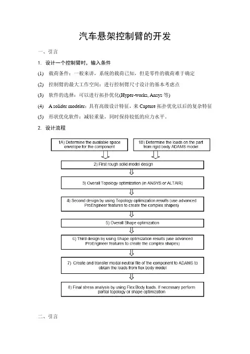
汽车悬架控制臂的开发一、引言1. 设计一个控制臂时,输入条件(1) 载荷条件:一般来讲,系统的载荷已知,但是零件的载荷难于确定(2) 控制臂的最大工作空间:进行控制臂尺寸设计的基本考虑点(3) 软件的选择:可以进行拓扑优化(Hyper-works, Ansys等)(4) A solider modeler:具有高级设计特征,来Capture拓扑优化以后的复杂特征(5) 形状优化软件:减轻重量,同时保持较低的应力水平。
2. 设计流程二、引言对各个步骤的详细解释Step 1A:确定控制臂的设计空间重要性:设计空间的大小与优化结果有关过小:优化的结果只是最优解的一个子集扩大:在一些载荷工况下面,这个部件可能和其它的部件重合。
方法:利用Pro/E 的Behavioral modeling (BMX) 确定设计空间Step 1B: 确定控制臂的载荷利用ADAMS建立悬架的模型,汽车在不同的行驶工况下。
作用在轮胎上的力已知,控制臂和车身或者转向臂的连接点已知。
由此可以确定作用在控制臂上的力。
(仅仅用于初始计算,由于控制臂的形状为初步的)Step 2 初步设计控制臂过重,利用了最大的设计空间,但是连接点的设计要准确。
Step 3: 拓扑优化目标:刚度最大,一阶固有频率最大等等。
约束:重量最轻,减小最大应力等等。
软件:Optistruc、Ansys等Step 4: 利用拓扑优化的结果进行二次设计(1) 考虑制造过程:锻造、铸造还是机加工。
(2) 在进行新的建模时,如何利用拓扑优化的结果Step 5 形状优化(Overall shape optimization)在进行拓扑优化时,没有加应力约束,此时需要进行形状优化。
Step 6:利用形状优化的结果进行第三次设计12% 的weight reduction; 13% stress reduction。
Step 7:考虑控制臂的柔性,确定作用在控制臂上的载荷控制臂的柔性可以改变作用在上面的载荷。
《某型汽车前悬架控制臂的结构分析与优化》篇一一、引言汽车作为现代交通工具的重要组成部分,其性能和舒适度直接关系到用户的驾驶体验。
前悬架控制臂作为汽车悬架系统的重要部件,其结构设计和性能优化对汽车的行驶稳定性和安全性具有重要影响。
本文将针对某型汽车的前悬架控制臂进行结构分析与优化,以提高其性能和可靠性。
二、某型汽车前悬架控制臂的结构分析某型汽车的前悬架控制臂主要由轴承、连接杆、支撑架等部分组成。
其中,轴承负责支撑和连接车轮,连接杆则将控制臂与车身连接起来,支撑架则为控制臂提供稳定的支撑。
在车辆行驶过程中,前悬架控制臂需要承受来自车轮的冲击力和侧向力,因此其结构必须具备足够的强度和刚度。
然而,该型汽车的前悬架控制臂在结构上存在一些不足之处。
例如,连接杆与轴承的连接部分较为薄弱,容易在长期使用过程中出现磨损和断裂。
此外,支撑架的稳定性也有待提高,以应对各种路况下的冲击和振动。
三、前悬架控制臂的优化方案针对某型汽车前悬架控制臂的结构特点及存在的问题,本文提出以下优化方案:1. 增强连接部分的强度:通过优化连接杆与轴承的连接结构,增加连接部分的厚度和强度,以减少磨损和断裂的可能性。
同时,采用高强度材料制作连接部分,提高其抗拉强度和耐磨性。
2. 提高支撑架的稳定性:通过改进支撑架的结构设计,增加其刚度和稳定性。
可以采用更为稳固的支架结构,或者增加支撑点的数量,以提高整个前悬架系统的稳定性。
3. 轻量化设计:在保证强度和刚度的基础上,对前悬架控制臂进行轻量化设计。
采用轻质材料制作控制臂,减少其重量,以提高车辆的燃油经济性和行驶性能。
4. 优化制造工艺:采用先进的制造工艺和技术,如数控加工、焊接等,提高前悬架控制臂的加工精度和装配质量。
同时,通过优化生产流程,降低制造成本,提高生产效率。
四、优化后的效果评估经过对某型汽车前悬架控制臂的结构分析与优化,可以预期达到以下效果:1. 提高前悬架系统的稳定性和可靠性:优化后的前悬架控制臂具有更高的强度和刚度,能够更好地承受来自车轮的冲击力和侧向力,提高车辆的行驶稳定性和安全性。
《某型汽车前悬架控制臂的结构分析与优化》篇一一、引言随着汽车行业的飞速发展,车辆性能和舒适性日益成为消费者关注的焦点。
前悬架控制臂作为汽车底盘系统的重要组成部分,对车辆行驶的平稳性和操控性具有至关重要的影响。
本文旨在分析某型汽车前悬架控制臂的结构特点,并提出相应的优化方案,以提高车辆的行驶性能和安全性。
二、某型汽车前悬架控制臂的结构分析某型汽车前悬架控制臂主要承担着支撑、转向和减震的作用。
其结构主要包括主臂、连接部分和衬套等部件。
主臂部分采用高强度钢材制成,具有较高的抗拉强度和抗扭强度,保证了在行驶过程中能够承受各种外力作用。
连接部分则通过螺栓等紧固件与转向节等部件相连,实现了转向和减震的功能。
衬套部分则起到减震和降噪的作用,提高了车辆的舒适性。
三、前悬架控制臂存在的问题及原因分析尽管某型汽车前悬架控制臂在结构上具有一定的优点,但在实际使用过程中仍存在一些问题。
例如,由于材料性能和加工工艺的限制,可能导致控制臂在承受外力时产生变形或断裂等问题。
此外,连接部分的紧固件可能因松动而导致安全隐患。
针对这些问题,本文将进行深入的分析,并探讨其产生的原因。
四、前悬架控制臂的优化方案针对某型汽车前悬架控制臂存在的问题,本文提出以下优化方案:1. 材料优化:选用更高强度、更轻量化的材料替代原有的高强度钢材,以提高控制臂的抗拉强度和抗扭强度。
同时,采用先进的加工工艺,提高材料的利用率和加工精度。
2. 结构优化:对控制臂的结构进行优化设计,减小应力集中和振动产生的可能性。
例如,可以改进连接部分的形状和布局,提高其承载能力和抗疲劳性能。
此外,还可以在控制臂上增加加强筋等结构,提高其整体刚度和稳定性。
3. 紧固件优化:对连接部分的紧固件进行升级,采用更先进的防松技术和紧固方法,确保在各种路况下都能保持紧固状态,从而提高车辆的安全性。
4. 减震降噪优化:改进衬套部分的材料和结构,提高其减震和降噪性能。
例如,可以采用粘弹性材料或液态衬套等新型减震元件,提高车辆的舒适性和静谧性。
《某型汽车前悬架控制臂的结构分析与优化》篇一一、引言汽车作为现代交通工具的重要组成部分,其性能和舒适度直接关系到驾驶者的驾驶体验和乘客的乘坐感受。
而前悬架控制臂作为汽车悬架系统的重要部件,对汽车的行驶稳定性和乘坐舒适性起着至关重要的作用。
本文将针对某型汽车的前悬架控制臂进行结构分析与优化,以期提高其性能和可靠性。
二、某型汽车前悬架控制臂的结构分析1. 结构组成某型汽车的前悬架控制臂主要由轴承、连接杆、固定座和臂体等部分组成。
其中,轴承用于支撑和控制臂的旋转运动,连接杆将控制臂与车辆其他部分连接起来,固定座用于固定控制臂在车身上的位置,而臂体则是控制臂的主要承载部分。
2. 工作原理前悬架控制臂通过连接杆与转向节相连,当车辆行驶过程中,由于路面不平或转向操作,会产生相应的力和力矩。
这些力和力矩通过控制臂传递到轴承和固定座,从而实现对车辆行驶状态的调整。
三、前悬架控制臂的优化方向1. 材料优化材料的选择对前悬架控制臂的性能和可靠性具有重要影响。
优化材料的选择可以降低控制臂的重量,提高其强度和耐久性。
例如,采用高强度钢材或合金材料可以显著提高控制臂的承载能力。
2. 结构优化通过对前悬架控制臂的结构进行优化,可以改善其应力分布,提高其抗疲劳性能和抗冲击性能。
例如,采用更加合理的连接方式和加强筋设计,可以增强控制臂的局部强度和刚度。
3. 制造工艺优化制造工艺的优化可以提高前悬架控制臂的加工精度和表面质量,从而降低其故障率和维护成本。
例如,采用先进的数控机床和自动化生产线,可以提高加工精度和效率;采用表面处理技术,可以提高控制臂的耐腐蚀性和耐磨性。
四、优化措施的实施与效果分析1. 材料优化措施的实施与效果分析针对某型汽车的前悬架控制臂,可以采用高强度钢材或合金材料替代原有的材料。
通过对比试验和分析,可以发现新材料的控制臂在承载能力和耐久性方面有明显提升,同时重量也有所降低,有利于提高整车的燃油经济性。
2. 结构优化措施的实施与效果分析针对前悬架控制臂的结构进行优化,可以通过仿真分析和实际测试来确定最佳的连接方式和加强筋设计。
《某型汽车前悬架控制臂的结构分析与优化》篇一一、引言汽车作为现代交通工具的重要组成部分,其性能和舒适度在很大程度上取决于其悬挂系统。
前悬架控制臂作为悬挂系统的重要部分,其结构设计和性能对汽车的行驶稳定性和乘坐舒适性具有重要影响。
本文将针对某型汽车的前悬架控制臂进行结构分析,并提出相应的优化方案。
二、某型汽车前悬架控制臂的结构分析某型汽车的前悬架控制臂主要由以下几部分组成:1. 主体部分:控制臂的主体部分承担着连接车架和转向节的重要作用,其形状和尺寸直接影响着悬挂系统的性能。
2. 轴承座:轴承座是控制臂与转向节连接的部分,其精度和强度对汽车的行驶稳定性有着重要影响。
3. 连接部分:控制臂的连接部分需要与车架和其他悬挂系统部件进行连接,其结构和强度也是关键因素。
三、前悬架控制臂的现行问题及挑战在结构分析中,我们发现某型汽车的前悬架控制臂存在以下问题:1. 材料选择:当前的控制臂材料虽然具有一定的强度和刚度,但在某些极端工况下仍存在变形和断裂的风险。
2. 结构优化:控制臂的结构设计可以进一步优化,以提高其承载能力和耐久性。
3. 制造工艺:制造过程中的精度和一致性对控制臂的性能有着重要影响,现行工艺存在一定的改进空间。
四、前悬架控制臂的优化策略针对上述问题,我们提出以下优化策略:1. 材料选择优化:采用更高强度和更好耐腐蚀性的材料,如铝合金或高强度钢,以提高控制臂的承载能力和耐久性。
2. 结构设计优化:通过有限元分析和仿真技术,对控制臂的结构进行优化设计,提高其承载能力和刚度。
同时,优化连接部分的设计,以提高连接的稳定性和可靠性。
3. 制造工艺优化:采用更精确的制造工艺,如数控机床加工和焊接技术,提高控制臂的制造精度和一致性。
此外,引入自动化检测设备,对制造过程中的质量控制进行严格把关。
五、优化后的效果评估经过优化后,某型汽车的前悬架控制臂在以下几个方面得到了显著提升:1. 承载能力:优化后的控制臂具有更高的承载能力,能够更好地应对极端工况下的挑战。
《某型汽车前悬架控制臂的结构分析与优化》篇一一、引言汽车作为现代交通工具的重要组成部分,其性能和舒适度在很大程度上取决于其悬挂系统。
前悬架控制臂作为悬挂系统的重要部分,其结构设计和性能对汽车的行驶稳定性和乘坐舒适性具有重要影响。
本文将针对某型汽车的前悬架控制臂进行结构分析,并提出相应的优化方案。
二、某型汽车前悬架控制臂的结构分析某型汽车的前悬架控制臂主要由钢板冲压件、连接件和轴承座等部分组成。
其中,钢板冲压件是控制臂的主要承载部分,负责承受车辆行驶过程中的各种力和力矩;连接件则用于将控制臂与车架和其他悬挂部件连接起来;轴承座则用于安装轴承,使控制臂能够顺畅地运动。
在结构上,该型汽车的前悬架控制臂采用了典型的双叉臂结构,这种结构具有较好的承载能力和运动性能。
然而,在实际使用过程中,仍存在一些结构上的问题。
例如,钢板冲压件的厚度和强度可能不足以承受高速行驶和复杂路况下的各种力和力矩;连接件的连接方式和强度也可能存在不足,导致在行驶过程中出现松动或脱落等问题。
三、前悬架控制臂的优化方案针对某型汽车前悬架控制臂的结构问题,我们可以从以下几个方面进行优化:1. 材料选择与强度提升:为了提高控制臂的承载能力和耐久性,可以选择更高强度、更轻质的材料。
如使用高强度钢材或铝合金材料替代传统的钢板冲压件,以减轻重量、提高强度。
同时,对关键部位的厚度进行适当增加,确保其能够承受更大的力和力矩。
2. 连接方式优化:对连接件进行重新设计,采用更可靠的连接方式。
如使用高强度的螺栓和螺母进行连接,并增加防松装置,确保在行驶过程中连接件不会出现松动或脱落等问题。
此外,还可以考虑采用一体式设计,减少连接点的数量,提高整体结构的刚性。
3. 结构优化:对控制臂的结构进行进一步优化,使其更加符合力学原理。
如通过有限元分析等方法对控制臂进行仿真分析,找出结构上的薄弱环节并进行改进。
同时,还可以借鉴其他先进车型的悬挂系统设计经验,对双叉臂结构进行改进,提高其运动性能和承载能力。
悬架系统开发流程---布置部分目标设定BENCHMARK在此主要是分析竞争车型的底盘布置。
底盘布置首先要确定出轮胎、悬架形式、转向系统、发动机、传动轴、油箱、地板、前纵梁结构(满足碰撞)等,因为这些重要的参数,如轮胎型号、悬架尺寸、发动机布置、驱动形式、燃油种类等在开发过程中要尽可能早地确定下来。
在此基础上,线束、管路、减振器、发动机悬置等才能继续下去悬架选择对各种后悬架结构型式进行优缺点比较,包括对后部轮罩间空间尺寸的分析比较,进行后悬架结构的选择。
常见的后悬架结构型式有:扭转梁式、拖曳臂式、多连杆式。
扭转梁式悬架优点:1.与车身连接简单,易于装配。
2.结构简单,部件少,易分装。
3.垂直方向尺寸紧凑。
4.底板平整,有利于油箱和后备胎的布置。
5.汽车侧倾时,除扭转梁外,有的纵臂也会产生扭转变形,起到横向稳定作用,若还需更大的悬架侧倾角刚度,还可布置横向稳定杆。
6.两侧车轮运转不均衡时外倾具有良好的回复作用。
7.在车身摇摆时具有较好的前束控制能力。
8.车轮运动特性比较好,操纵稳定性很好,尤其是在平整的道路情况下。
9.通过障碍的轴距具有相当好的加大能力,通过性好。
10.如果采用连续焊接的话,强度较好。
缺点:1.对横向扭转梁和纵向拖臂的连续焊接质量要求较高。
2.不能很好地协调轮迹。
3.整车动态性能对轴荷从空载到满载的变化比较敏感。
4.但这种悬架在侧向力作用时,呈过度转向趋势。
另外,扭转梁因强度关系,允许承受的载荷受到限制。
扭转梁式悬架结构简单、成本低,在一些前置前驱汽车的后悬架上应用较多。
拖曳臂式悬架优点:1.Y轴和X轴方向尺寸紧凑,非常有利于后乘舱(尤其是轮罩间宽度尺寸较大)和下底板备胎及油箱的布置。
2.与车身的连接简单,易于装配。
3.结构简单,零件少且易于分装;4.由于没有衬套,滞后作用小。
5.可考虑后驱。
缺点:1.由于沿着控制臂相对车身转轴方向控制臂较大的长宽比,侧向力对前束将产生不利的影响。
2.车身摇摆(body roll)对外倾产生不利影响;(适当的控制臂转轴有可能改善外倾的回复能力,但这导致轮罩间宽度尺寸的减小。
悬架系统开发流程下载温馨提示:该文档是我店铺精心编制而成,希望大家下载以后,能够帮助大家解决实际的问题。
文档下载后可定制随意修改,请根据实际需要进行相应的调整和使用,谢谢!并且,本店铺为大家提供各种各样类型的实用资料,如教育随笔、日记赏析、句子摘抄、古诗大全、经典美文、话题作文、工作总结、词语解析、文案摘录、其他资料等等,如想了解不同资料格式和写法,敬请关注!Download tips: This document is carefully compiled by theeditor.I hope that after you download them,they can help yousolve practical problems. The document can be customized andmodified after downloading,please adjust and use it according toactual needs, thank you!In addition, our shop provides you with various types ofpractical materials,such as educational essays, diaryappreciation,sentence excerpts,ancient poems,classic articles,topic composition,work summary,word parsing,copy excerpts,other materials and so on,want to know different data formats andwriting methods,please pay attention!悬架系统开发流程详解悬架系统是汽车的重要组成部分,它直接影响着车辆的行驶稳定性和乘坐舒适性。
《某型汽车前悬架控制臂的结构分析与优化》篇一一、引言汽车作为现代交通工具的重要组成部分,其性能和舒适度在很大程度上取决于其悬挂系统。
前悬架控制臂作为悬挂系统的重要部分,对汽车的操控稳定性、乘坐舒适性以及轮胎的磨损等有着直接的影响。
本文将对某型汽车前悬架控制臂的结构进行详细分析,并探讨其优化方法。
二、某型汽车前悬架控制臂的结构分析某型汽车的前悬架控制臂主要由以下几个部分组成:轴承座、连接杆、控制臂主体以及固定点。
其中,轴承座负责支撑车轮,连接杆将控制臂与转向系统相连,控制臂主体则负责传递力和扭矩,而固定点则是控制臂与车架的连接处。
在结构上,该型汽车的前悬架控制臂采用了高强度钢材制造,以保证其足够的强度和刚度。
同时,其设计考虑了轻量化、耐久性和制造工艺等因素。
此外,该控制臂还具有较好的抗冲击性能和抗疲劳性能,能够满足汽车在各种路况下的使用需求。
三、前悬架控制臂的优化方法虽然某型汽车的前悬架控制臂在结构和性能上已经相当优秀,但仍存在一些可优化的空间。
下面我们将从材料、结构和制造工艺三个方面进行探讨。
1. 材料优化首先,可以考虑采用更高级别的材料来提高前悬架控制臂的性能。
例如,采用轻质合金或复合材料来替代部分高强度钢材,以实现轻量化的同时保持足够的强度和刚度。
此外,采用耐磨、耐腐蚀的材料也可以提高控制臂的耐久性。
2. 结构优化在结构上,可以通过优化控制臂的几何形状和尺寸来提高其性能。
例如,通过优化轴承座和连接杆的布局,可以改善车轮的支撑和转向性能。
同时,通过优化控制臂主体的结构,可以更好地传递力和扭矩,提高汽车的操控稳定性和乘坐舒适性。
此外,针对某些特定路况或使用需求,还可以对控制臂进行定制化设计。
例如,针对经常行驶在颠簸路面的汽车,可以加强控制臂的抗冲击性能;针对需要高速行驶的汽车,可以优化其频率响应特性,以减小车身的振动。
3. 制造工艺优化在制造工艺方面,可以通过引入先进的加工技术和设备来提高前悬架控制臂的制造精度和效率。
某轿车悬架控制臂有限元分析与结构优化
在轿车悬架系统的优化设计中,为保证整车的行驶安全性和燃油经济性,需要全面考虑悬架零件的结构强度、刚度和重量等。
对于具有复杂形状和边界条件的悬架零件而言,以往单纯基于有限元方法的结构改进设计往往带有盲目性。
因此,本文结合某轿车底盘开发项目,综合使用多体动力学、有限元和结构优化方法,进行悬架某控制臂概念设计方案的有限元分析和结构优化研究。
全文围绕该解决方案,首先进行了悬架控制臂的载荷分析,在对比并选择了具体的载荷获取方法之后,对载荷分析的典型极限工况进行了总结和分析,并计算得到各工况的轮胎接地力,然后以此作为输入条件,用该车的ADAMS悬架模型加载仿真,并提取悬架控制臂各工况下的载荷。
其次,利用HyperWorks软件对选取的悬架控制臂的概念设计方案进行有限元建模,然后,以之前提取的载荷为边界条件对其进行结构强度分析,并作了自由模态分析。
最后,结合结构工艺性要求,对概念设计方案先后进行了拓扑优化和形状优化共两轮优化设计以及相应的改进设计,并对比了两轮优化前后的控制臂结构强度、刚度、质量、固有频率等,最终优化结果基本实现了减轻零件重量而不牺牲关键性能的目标。
电控智能悬架研发方案一、实施背景随着汽车技术的不断进步,消费者对车辆舒适性和操控性的需求也在日益增长。
电控智能悬架作为提升车辆性能、满足消费者需求的关键技术,已经成为了汽车产业发展的一个重要方向。
实施电控智能悬架研发方案,旨在提升我公司在汽车悬挂系统领域的竞争力,推动产业结构改革。
二、工作原理电控智能悬架系统主要通过传感器实时监测车辆行驶状态,将信号传输至控制器进行处理,再根据处理结果控制执行机构动作,以实现阻尼力、刚度和高度的独立调节。
这种系统能够有效地提高车辆的舒适性和操控性,同时降低振动和噪音。
三、实施计划步骤1.需求分析:明确电控智能悬架系统的功能需求,包括阻尼力、刚度和高度的调节范围、调节速度等。
2.硬件设计:根据需求分析结果,设计合适的传感器、控制器和执行机构。
选择具备良好性能和可靠性的元器件,确保系统的稳定性。
3.软件编写:开发一套能够实现实时监测、信号处理和控制的软件系统。
软件应具备良好的人机交互界面,方便用户进行操作和调试。
4.系统集成与测试:将硬件和软件集成到一起,进行系统测试。
对测试过程中发现的问题进行修正和优化,确保系统的性能和稳定性达到预期要求。
5.产业化推广:将研发成功的电控智能悬架系统应用于实际生产中,进行产业化推广。
同时,持续收集用户反馈,对系统进行持续改进和优化。
四、适用范围本研发方案适用于各类乘用车、商用车及特种车辆的悬挂系统。
通过推广应用,可提高车辆的整体性能,满足不同消费者的需求。
五、创新要点1.采用了先进的传感器技术,能够实时监测车辆行驶状态,为控制系统提供准确的输入数据。
2.采用了高性能的微处理器作为控制器核心,确保系统能够快速、准确地处理数据并输出控制指令。
3.实现了阻尼力、刚度和高度的独立调节,可根据车辆行驶状态和用户需求进行动态调整,提高了车辆的舒适性和操控性。
4.采用了人性化的软件界面,方便用户进行操作和调试,提高了系统的易用性。
5.系统采用了模块化设计思想,便于维护和升级,降低了生产成本。
《某型汽车前悬架控制臂的结构分析与优化》篇一一、引言随着汽车行业的迅猛发展,汽车的结构设计及性能优化已成为汽车工程领域的重要研究方向。
其中,汽车前悬架控制臂作为连接车架与前轮的关键部件,其结构特性和工作状态对车辆的稳定性、行驶平顺性及安全性具有重要影响。
本文将针对某型汽车的前悬架控制臂进行结构分析,探讨其工作原理和潜在优化方案。
二、某型汽车前悬架控制臂的结构分析(一)基本构造某型汽车的前悬架控制臂主要由多个部分组成,包括支架、控制臂本体、轴承等。
其中,支架用于连接车架,控制臂本体通过轴承与前轮相连,具有承受横向及纵向载荷的功能。
(二)结构特点该型汽车前悬架控制臂的设计充分考虑了结构强度、抗冲击性能及耐用性,具有较高的抗扭强度和承载能力。
同时,其结构紧凑,能够适应复杂的行驶环境。
(三)工作原理前悬架控制臂通过配合减震器和弹簧等元件,实现车辆行驶过程中的减震和稳定功能。
当车辆行驶在不平坦的路面上时,前悬架控制臂能够根据路面状况调整车轮的姿态,保证车辆的稳定性和行驶平顺性。
三、前悬架控制臂的潜在问题与优化方向(一)潜在问题尽管某型汽车的前悬架控制臂在结构上具有一定的优势,但在实际使用过程中仍存在一些问题,如材料强度不足、易磨损等。
这些问题可能导致车辆行驶过程中的安全隐患。
(二)优化方向针对潜在问题,本文提出以下优化方向:1. 材料优化:采用高强度材料替代原有材料,以提高控制臂的抗冲击性能和承载能力。
同时,选用耐磨性更好的材料,以延长控制臂的使用寿命。
2. 结构优化:通过优化控制臂的结构设计,减少应力集中和磨损区域,提高控制臂的耐久性。
同时,采用先进的制造工艺,如注塑成型、锻造等,以提高生产效率和产品质量。
四、结论通过对某型汽车前悬架控制臂的结构分析,我们深入了解了其工作原理和潜在问题。
在了解现有问题的前提下,本文提出了针对性的优化方案。
未来,通过采用优化材料、优化结构和采用先进制造工艺等方法,可以进一步提高前悬架控制臂的性能和寿命,为汽车行业的发展提供有力支持。
《某型汽车前悬架控制臂的结构分析与优化》篇一一、引言随着汽车行业的飞速发展,车辆性能与驾驶体验已成为消费者选购车辆的重要考量因素。
其中,汽车前悬架控制臂作为汽车底盘的重要组成部分,对汽车的行驶稳定性和舒适性有着重要影响。
本文将对某型汽车前悬架控制臂的结构进行详细分析,并提出相应的优化方案。
二、某型汽车前悬架控制臂的结构分析某型汽车前悬架控制臂主要采用高强度钢材制成,具有承载能力强、耐久性好等优点。
其结构主要包括主臂、连接部分和球头等部分。
主臂负责承受车轮的垂直载荷和横向力;连接部分将主臂与车辆其他部分相连,传递动力和运动;球头则使车轮在运动中保持一定的活动空间。
然而,该型汽车前悬架控制臂在长期使用过程中,可能会因材料疲劳、外界因素等原因导致性能下降,影响行驶安全。
因此,对前悬架控制臂的结构进行深入分析,找出潜在问题,是优化其性能的关键。
三、前悬架控制臂存在的问题及原因分析通过对某型汽车前悬架控制臂的实地考察和实验数据收集,我们发现存在以下问题:1. 材料疲劳:由于长期承受重载和振动,高强度钢材容易出现疲劳裂纹,导致控制臂强度降低。
2. 连接部分松动:连接部分的紧固件可能因振动而松动,导致连接失效。
3. 球头磨损:球头与转向节之间的摩擦可能导致球头磨损,影响车轮的运动轨迹。
针对上述问题,我们进行了深入的原因分析,发现除了材料本身的使用寿命限制外,设计上的不足、制造工艺的缺陷以及使用环境的影响都是导致这些问题的原因。
四、前悬架控制臂的优化方案针对上述问题,我们提出以下优化方案:1. 材料优化:采用更高强度、耐疲劳的材料,以提高控制臂的使用寿命。
2. 设计优化:改进连接部分的紧固方式,增加防松装置,以提高连接的稳定性。
同时,优化球头的设计,减少摩擦和磨损。
3. 制造工艺优化:采用先进的制造工艺,如热处理、表面强化等,提高控制臂的耐久性和抗腐蚀性。
五、结论通过对某型汽车前悬架控制臂的结构分析与优化,我们不仅提高了其性能和寿命,还为汽车行业的发展提供了有益的参考。
《某型汽车前悬架控制臂的结构分析与优化》篇一一、引言随着汽车行业的飞速发展,车辆性能和舒适性日益成为消费者关注的焦点。
前悬架控制臂作为汽车底盘系统的重要部分,对于车辆行驶的稳定性、舒适性及安全性有着重要的影响。
本文以某型汽车为例,深入探讨其前悬架控制臂的结构设计与优化方法。
二、某型汽车前悬架控制臂的结构分析某型汽车的前悬架控制臂是典型的钣金冲压件,其结构主要包括臂体、轴承座及连接耳等部分。
1. 臂体部分:主要负责支撑与传递载荷,其结构形式与材质直接影响到悬架系统的刚度与强度。
臂体一般采用高强度钢材制造,以承受车辆行驶过程中的各种载荷。
2. 轴承座部分:与转向节等部件相连,承担着将转向力传递至车轮的任务。
轴承座的结构设计需满足强度、刚度及耐磨性要求。
3. 连接耳部分:连接臂体与车辆其他部件,如减震器等。
连接耳的设计需保证连接的可靠性与稳定性。
三、前悬架控制臂的优化方法针对某型汽车前悬架控制臂的结构特点,本文提出以下优化方法:1. 材料优化:采用高强度、轻质材料替代传统钢材,以降低整体重量,提高刚度与强度。
同时,采用热处理工艺提高材料的抗疲劳性能。
2. 结构优化:通过有限元分析等方法,对控制臂进行结构分析与优化设计。
针对应力集中、易磨损等部位进行结构改进,提高整体结构的可靠性与耐久性。
3. 工艺优化:采用先进的冲压、焊接等工艺技术,提高控制臂的制造精度与质量。
同时,采用自动化生产线,提高生产效率与降低成本。
4. 润滑与防护:对轴承座等易磨损部位进行润滑处理,延长使用寿命。
对整体结构进行防腐、防锈处理,提高耐候性能。
四、优化效果分析经过对某型汽车前悬架控制臂的结构分析与优化,可以预期达到以下效果:1. 提高车辆行驶的稳定性与舒适性:优化后的控制臂具有更高的刚度与强度,可有效抵抗各种载荷,提高车辆行驶的稳定性。
同时,优化后的结构能够更好地吸收路面冲击,提高乘坐舒适性。
2. 降低油耗与排放:优化后的控制臂重量更轻,可降低车辆的整备质量,从而降低油耗与排放。
汽车悬架控制臂的开发一、引言1. 设计一个控制臂时,输入条件(1) 载荷条件:一般来讲,系统的载荷已知,但是零件的载荷难于确定(2) 控制臂的最大工作空间:进行控制臂尺寸设计的基本考虑点(3) 软件的选择:可以进行拓扑优化(Hyper-works, Ansys等)(4) A solider modeler:具有高级设计特征,来Capture拓扑优化以后的复杂特征(5) 形状优化软件:减轻重量,同时保持较低的应力水平。
2. 设计流程二、引言对各个步骤的详细解释Step 1A:确定控制臂的设计空间重要性:设计空间的大小与优化结果有关过小:优化的结果只是最优解的一个子集扩大:在一些载荷工况下面,这个部件可能和其它的部件重合。
方法:利用Pro/E 的Behavioral modeling (BMX) 确定设计空间Step 1B: 确定控制臂的载荷利用ADAMS建立悬架的模型,汽车在不同的行驶工况下。
作用在轮胎上的力已知,控制臂和车身或者转向臂的连接点已知。
由此可以确定作用在控制臂上的力。
(仅仅用于初始计算,由于控制臂的形状为初步的)Step 2 初步设计控制臂过重,利用了最大的设计空间,但是连接点的设计要准确。
Step 3: 拓扑优化目标:刚度最大,一阶固有频率最大等等。
约束:重量最轻,减小最大应力等等。
软件:Optistruc、Ansys等Step 4: 利用拓扑优化的结果进行二次设计(1) 考虑制造过程:锻造、铸造还是机加工。
(2) 在进行新的建模时,如何利用拓扑优化的结果Step 5 形状优化(Overall shape optimization)在进行拓扑优化时,没有加应力约束,此时需要进行形状优化。
Step 6:利用形状优化的结果进行第三次设计12% 的weight reduction; 13% stress reduction。
Step 7:考虑控制臂的柔性,确定作用在控制臂上的载荷控制臂的柔性可以改变作用在上面的载荷。
计算发现,考虑控制臂的柔性以后,作用在控制臂上载荷的改变可以达到+/-33%,从而可能导致Fatige的改变。
Step 8:最终设计-部分拓扑优化和部分形状优化液锻和铸锻控制臂性能的比较A comparative study between two families of front lower control arms manufactured via. Cast-Forge and NRC (New Rheocasting Process) was carried out at Citation Corporation to understand the process capabilities of NRC in automotive suspension applications.一、研究背景目的:A benchmarking research and development program was funded and carried out within Citation Corporation to evaluate and confirm process capabilities of NRC, as well as its feasibility and competitiveness in automotive suspension applications.方法:●Reverse engineering the existing Cast-Forge control arm●Analyze the existing component to establish baseline for comparativestudy●Develop concept design for NRC●Optimize prototype design for weight, performance, andmanufacturability●Utilize process simulation to help establish process parameters●Manufacture prototype control arms●Bench test both families of control arms for materials evaluation andcomponent performance●Analyze test results;Lessons learned assessment二、比较研究的步骤和内容1. 逆向工程对目前供应商的样件进行测绘2. 基NRC制造的控制臂的概念设计The prototype design was intended to be conservative in structural performance, but aggressive in exploring manufacturing process capability. It has relatively long thin-walled H-section arms resulting much improved fore/aft stiffness while maintaining the same weight as the existing control arm. The effects of this design concept on process capability will be discussed in detail in the next two sections.3. 基于NRC的控制臂的制造(1)计算机模拟Figure 4的模拟结果与Figure5的实际制造情况具有较好的一致性。
(2)X射向检查有无气孔4. Slug (毛坯、连皮) material analysis检验材料的均匀性To understand the quality of the NRC slurry material that was introduced into the die cavity to form the part, some preliminary microstructure and chemical analysis were carried out. Figure 7 describes the sample location out off a typical slug.5. 材料的性能Tensile specimens have been cut from both families of control arms. The tensile test results are tabulated in the following table:6. 结构分析与控制臂的性能实验(1)实验工况●Ultimate strength in aft direction●Ultimate strength in vertical direction●Accelerated fore/aft fatigue●Accelerated vertical fatigueThe applied loads for the accelerated fatigue tests were established based on analysis results & estimated fatigue life for the existing control arm to be within the range of 100,000 –200,000 cycles. The loads used for the accelerated fatigue tests were +/- 13,336 N for the fore/aft test and +40,009/0 N for the vertical test, respectively.载荷是通过球铰加上去的。
(2)控制臂前后方向的强度与疲劳计算的弯曲载荷为80,000N,铸造控制臂的弯曲载荷为87,000N,NRC 件的弯曲强度为109,375N。
前后方向的疲劳强度利用计算的应力结果和控制臂的破坏形式的对比(3)垂直方向的强度与水平方向的状况基本一致Optimizing Designs of Aluminum Suspension Components Using anIntegrated ApproachAlcoa Inc.(一种新的铝件加工工艺)In 1994, Alcoa leveraged its experience with high integrity aluminum castings from the aerospace business to quickly enter the aluminum chassis and suspension components market. In early 1995, Alcoa upgraded a proprietary casting process called Vacuum Riserless / Pressure Riserless Casting (VRC/PRC) and adapted it to the needs of the automotive chassis and suspension components market.VRC/PRC is a modified low-pressure, permanent mold casting process which uses vacuum and pressure to “bottom fill” a steel mold from a molten aluminum bath. VRC was developed in 1950’s by the Alcoa Casting & Forging Research Lab and was commercialized in the 1960’s. PRC was added to VRC in 1985 and the combined process is called VRC/PRC. The VRC/PRC casting machine consists of a vertical hydraulic press with a steel mold (upper and lower halves) that is bolted on to the machine’s lower platen.控制臂及其其中衬套的作用高性能的球头2003-01-3668 High Performance Ball Joint1. 研究对象:球头+塑料球座(Ball joints constructed with plastic bearing)塑料球座的弹性、表面粗糙度和抗温度的特性。