KERNB阿牛巴流量计技术说明书
- 格式:pdf
- 大小:14.12 MB
- 文档页数:28

TABLE OF CONTENTS Introduction (4)Specifications (6)Installation (7)Operational Start-Up (9)Troubleshooting (11)Flow Monitor Information (12)Repair Kit Information (13)Statement of Warranty (15)INTRODUCTIONFluid entering the meter passes through the inlet flow straightener which reduces its turbulent flow pattern and improves the fluid’s velocity profile. Fluid then passes through the turbine blades causing it to rotate at a speed proportional to the fluid velocity. As each blade passes through the magnetic field, created at the base of the pickoff transducer, AC voltage (pulse) is generated in the pick-up coil (see Figure 1). These impulses produce an output frequency proportional to the volumetric flow through the meter. The output frequency is used to represent flow rate and/or totalization of fluid passing through the turbine flow meter.FIGURE 1Schematic illustration of electric signalgenerated by rotor movementTURBINE METERThe FTB-1400 Series Turbine Flow Meter is designed to withstand the rigorous demands of the most remote flow measurement applications. The FTB-1400 Series Flow Meter maintains measurement accuracy and mechanical integrity in the corrosive and abrasive fluids commonly found in oil field waterflood project pipelines, in-situ mining operations, offshore facilities and plant locations. Simple to install and service, it can operate in any orientation (horizontal to vertical) as long as the“flow direction” arrow is aligned in the same direction as the actual line flow. For optimum performance, the flow meter should be installed with a minimum of 10 diameters upstream pipe length and 5 diameters downstream pipe length.FIGURE 2Typical cross-section of FTB-1411 throughFTB-1441 turbine flow meterSPECIFICATIONSMATERIALS of CONSTRUCTION: Body : 316 Stainless SteelRotor : CD4MCU Stainless SteelRotor Support and Bearings : 316 Stainless SteelRotor Shaft : Tungsten CarbideOPERATING LIMITATIONS:Temperature: -150 °F to +350 °F (-101 °C to +177 °C) The metershould not be subjected to temperatures above +350° F(177° C), or below -150° F (-101° C) or the freezingpoint of the metered liquid. High temperatures willdamage the magnetic pick-up, while lower temperatureswill limit the rotation of the rotor.Pressure : Maximum pressure ratings as follows:5,000 psi ─ all NPT meters up to 2"2,000 psi ─ 3" male NPT1,500 psi ─ 4" male NPT1,000 psi ─ 6" male NPT800 psi ─ all grooved end metersNote: Consult factory for pressure ratings for flanged meters. Accuracy:± 1.0% of reading Repeatability: ± 0.1%Calibration: Water (NIST Traceable Calibration) Corrosion: All FTB-1400 series turbine meters are constructed ofstainless steel and tungsten carbide. The operator mustensure that the operating fluid is compatible with thesematerials. Incompatible fluids can cause deterioration ofinternal components and cause a reduction in meteraccuracy.Pulsation andVibration: Severe pulsation and mechanical vibration will affectaccuracy and shorten the life of the meterFiltration: If small particles are present in the fluid, it is recommendedthat a strainer be installed upstream of the meter (see Table 1 WARNING: Pressure in excess of allowable rating may cause the housing to burst and cause serious personal injury.FLOW MONITOR:For a complete flow monitor package, Omega offers the FTB-1400 Series Flow Monitors (see Appendix B on page 12 for flow monitor information). These digital signal processing displays utilize the low-level frequency input from the FTB-1400 Series Turbine Meters to calculate flow rate and total. When ordered with an Omega FTB-1400 Series Turbine Meter, the included factory calibration will provide dependable and accurate flow information.REPAIR KIT:The FTB-1400 Series Turbine Meter Repair Kit is designed for easy field service of a damaged flow meter, rather than replacing the entire flow meter (see Appendix B on page 12 for repair kit information).Repair parts are constructed of stainless steel alloy and tungsten carbide and are factory calibrated to ensure accuracy throughout the entire flow range. Each kit is complete and includes the calibrated K-factor which is used to recalibrate the flow monitor or other electronics to provide accurate output data.INSTALLATION INSTRUCTIONSPrior to installation, the flow meter should be checked internally for foreign material and to ensure the turbine rotor spins freely. Fluid lines should also be checked and cleared of all debris.The flow meter must be installed with the flow arrow, etched on the exterior of the meter body, pointing in the direction of fluid flow. Though the meter is designed to function in any position it is recommended, where possible, to install horizontally with the magnetic pick-up facing upward.The liquid being measured should be free of any large particles that may obstruct rotation of the rotor. If particles are present, a mesh strainer should be installed upstream before operation of the flow meter. (See Table 1 on page 8.)TABLE 1 Strainer Mesh Installation DetailsThe preferred plumbing setup is one containing a by-pass line (Figure 3 on page 10) that allows meter inspection and repair without interrupting flow. If a by-pass line is not utilized, it is important that all control valves be located downstream of the flow meter (Figure 4 on page 10).This is true with any restriction in the flow line that may cause the liquid to flash. If necessary, air eliminators should be installed to ensure that the meter is not incorrectly measuring entrained air or gas.PARTNUMBER STRAINER MESH CLEARANCE FILTER SIZE FTB-1411, FTB-142160 × 60 .0092 260 Micron FTB-1412, FTB-142260 × 60 .0092 260 Micron FTB-1413, FTB-142360 × 60 .0092 260 Micron FTB-142460 × 60 .0092 260 Micron FTB-1425 60 × 60 .0092 260 MicronFTB-1431 20 × 20 .0340 .86mm FTB-1441 20 × 20 .0340 .86mmCAUTION: Damage can be caused by striking an empty meter with a high velocity flow stream.It is recommended that a minimum length, equal to ten (10) pipe diameters of straight pipe, be installed on the upstream side and five (5) diameters on the downstream side of the flow meter. Otherwise, meter accuracy may be affected. Piping should be the same size as the meter bore or threaded port size.Do not locate the flow meter or connection cable close to electric motors, transformers, sparking devices, high voltage lines, or place connecting cable in conduit with wires furnishing power for such devices. These devices can induce false signals in the flow meter coil or cable, causing the meter to read inaccurately.If problems arise with the flow meter and monitor, consult Appendix A (Troubleshooting Guide) on page 11. If further problems arise, consult the factory.If the internal components of the turbine flow meter are damaged beyond repair, turbine meter repair kits are available. Information pertaining to the turbine meter repair kits is referenced in Appendix B on page 12.OPERATIONAL START-UPThe following steps should be followed when installing and starting the meter.WARNING: Make sure that fluid flow has been shut off and pressure in the line released before attempting to install the meter in an existing system.1. After meter installation, close the isolation valves and open theby-pass valve. Flow liquid through the by-pass valve for sufficient time to eliminate any air or gas in the flow line.CAUTION: High velocity air or gas may damage the internal components of the meter.2. Open upstream isolating valve slowly to eliminate hydraulic shockwhile charging the meter with the liquid. Open the valve to full3. Open downstream isolating valve to permit meter to operate.4. Close the by-pass valve to a full closed position.5. Adjust the downstream valve to provide the required flow ratethrough the meter. Note: The downstream valve may be used as a control valve.FIGURE 3Meter installation utilizing a by-pass line(Shown with an FTB-1400 Series Flow Monitor)FIGURE 4Meter installation without utilizing a by-pass lineAPPENDIX ATROUBLESHOOTING GUIDE Trouble Possible Cause RemedyMeter indicates higher than actual flow rate -Cavitation-Debris on rotor support-Build up of foreign materialon meter bore-Gas in liquid-Increase back pressure-Clean meter-Clean meter-Install gas eliminatorahead of meterMeter indicates lower than actual flow rate -Debris on rotor-Worn bearing-Viscosity higher than calibrated-Clean meter and add filter-Clean meter and add filter-Recalibrate monitorErratic system indication, meter alone works well (remote monitor application only) Ground loop in shielding Ground shield one placeonly. Look for internalelectronic instrumentground. Reroute cablesaway from electrical noiseIndicator shows flow when shut off Mechanical vibration causesrotor to oscillate without turningIsolate meterNo flow indication. Full or partial open position Fluid shock, full flow into drymeter or impact caused bearingseparation or broken rotor shaftRebuild meter with repairkit and recalibrate monitor.Move to location wheremeter is full on start-up oradd downstream flowcontrol valveErratic indication at low flow, good indication at high flow Rotor has foreign materialwrapped around itClean meter and add filterNo flow indication Faulty pick-up Replace pick-upSystem works perfect, except indicates lower flow over entire range By-pass flow, leak Repair or replace by-passvalves, or faulty solenoidvalvesMeter indicating highflow, upstream pipingat meter smaller thanmeter boreFluid jet impingement on rotor Change pipingOpposite effects of above Viscosity lower than calibrated Change temperature,change fluid or recalibratemeter11APPENDIX BFTB-1400 SERIES FLOW MONITOR Simplified Version• Displays rate and/or total• Large 8 digit by 3/4” display• Front panel programming• NEMA 4X enclosure• Five selectable units of measure• Programs in seven simple stepsPart Number InformationFTB 1400 X DMounting StyleM = Meter MountR =Remote MountS =Swivel Mount Advanced Version• Displays rate and/or total• Large 8 digit by 3/4” display• Front panel programming• NEMA 4X enclosure• Thirteen selectable units of measure• Selection of time intervals for rate measurement• Ten point linearization• Provides additional programming optionsPart Number InformationFTB 1400 X D AMounting StyleM = Meter MountR =Remote MountS =Swivel Mount1213FTB-1400 REPAIR KITFigure 5Typical turbine meter component directoryFlow Meter SizeRepair Kit FitsMeter Part NumberRepair KitPart Number3/8" FTB-1411,FTB-1421 FTB-1400A-RK 1/2" FTB-1412, FTB-1422 FTB-1400B-RK 3/4" FTB-1413, FTB-1423 FTB-1400C-RK 7/8" FTB-1424 FTB-1400D-RK 1" FTB-1425 FTB-1400E-RK 1-1/2" FTB-1431 FTB-1400F-RK 2" LowFTB-1441 FTB-1400F-RK Standard Magnetic Pick-upAll Meter SizesFTB-1400-MPNOTES 141516。

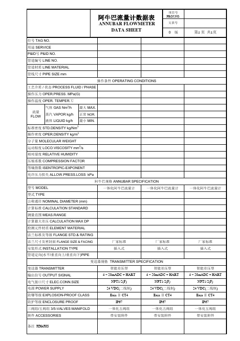
阿牛巴流量计的安装流量计技术指标阿牛巴流量计(均速管流量计)测量范围广泛,适用于大部分现场介质的测量。
是公认的节能型流量仪表。
今天就阿牛巴流量计普通的安装方式给大家详细总结下,对于生产型的企业大家都知道,阿牛巴流量计现场安装正常采用的是直接插入式(也就是焊接式)的连接方式。
1,安装首先的前提还是要确认现场直管段是否符合要求,具体要求可以参考相关手册或者咨询公司技术部门,然后根据现场流体方向确定流量计的安装方向。
2,在方向确定好之后,借助开孔器在管道上开孔(常规开孔大小为25mm)a,单面支撑;也就是说,在管道上根据阿牛巴传感器尺寸开一个孔,这样的安装方式适合现场口径小于600mm的管道,因为在小孔径的安装方式下,这样的安装方式足以保证传感器本身的稳定性,保证测量精度。
b;双面支撑;确定安装方向后,在管道上对称位置上开两个同样大小的孔,和上面单面支撑是相对的,也就是说,对于大口径的测量,为了保证传感器的稳定性,要采用双面固定的方式来安装阿牛巴流量计。
3,将阿牛巴流量计插入管道中,用点焊的方式将传感器固定在正确的位置上,但是要求探头部分在整个管道内径且与中心线在同一条中心线上4,最后将整个焊口全部焊接好,并对焊接部分做防锈处理。
而对于现场水泥管道,为了现场安装方便,公司会随阿牛巴流量计同时配备一块钢板,钢板与现场管道用螺栓对卯,然后阿牛巴流量计和钢板还是采取上述安装方式。
一、指针抖动:1.轻微指针抖动:一般由于介质波动引起。
可采用增加阻尼的方式来克服。
2.中度指针抖动:一般由于介质流动状态造成。
对于气体一般由于介质操作压力不稳造成。
可采用稳压或稳流装置来克服或加大浮子流量计气阻尼。
3.剧烈指针抖动:主要由于介质脉动,气压不稳或用户给出的气体操作状态的压力、温度、流量与浮子流量计实际的状态不符,有较大差异造成浮子流量计过量程。
二、指针停到某一位置不动主要原因是浮子流量计的浮子卡死一般由于金属管转子流量计使用时开启阀门过快,使得浮子飞快向上冲击止动器,造成止动器变形而将浮子卡死。

ABB流量计操作说明XE电磁流量计设置步骤:(1)通电后,按”#”,进入总菜单,按”▼”或”▲”翻页翻到” prog.protectionon”按住”▲”3秒钟进入,然后按”▼”或”▲”选择,”off”,再按住”▲”3秒确认.(2)按”▼”或”▲”翻到”cede number ****”, 按住”▲”3秒,输入:4000,再翻到”prog prot code 0”,输入4000.(3)按”▼”或”▲”翻到”submenu primary”,按住”▲”3秒进入,确认管径,CZ、CS的值,如管径不对应传感器,按“#”返回上一层菜单后,按”▼”或”▲”翻到重新出现“submenu primary”,进入后出现“metersize ***mm **in”按住”▲”3秒进入,在右下角出现“***mm**in_”,再按”▼”或”▲”修改为相应的口径。
然后按“▲”3秒确认。
(4)修改口径后,再按”▼”或”▲”翻到“store data in extomal EEPROM”按住”▲”3秒进入,出现“YES?”就再按住”▲”3秒进行确认保存。
(5)修改单位、量程,翻页翻到”submenu unit”,按住”▲”3秒进入,选择所需单位,按“#”返回上一层菜单,然后翻到“RANGE **** m3/h”,按”▼”或”▲”选择所需的量程,然后按”▲”3秒确认。
按“#”返回上一层菜单,再按”▼”或”▲”翻到“store data in extomal EEPROM”按住”▲”3秒进入,出现“YES?”就再按住”▲”3秒进行确认保存。
(6)按”▼”或”▲”翻页到”submenu detectore pipe”,空管检测,按住”▲”3秒进入,出现“detextore pipe on/off”将其改为“ON”,然后按”▼”翻到“Adiust Detertorepipe”空管检测调整。
按住”▲”3秒进入, 然后按”▼”或”▲”修改其数值“Adiust2000:,改为2000左右,然后按”▲”3秒确认。

德尔塔巴流量计使用说明书北京肯普尔科技有限公司二OO五年二月目录一、序言 (3)二、基本原理与结构特点 (3)三、特点 (6)四、德尔塔巴基本安装方式及其所需直管段 (9)五、调试及运行 (14)一、序言在流量测量的过程中,由于被测介质的复杂,测量方法亦是多种多样,由此也就出现了各种基于不同测量原理的流量传感器或节流件。
按测量方法和结构来讲,可分为:差压式,式,涡街式,超声波式,热式,科里奥式;按安装方式可分为:插入式,封闭管道式,明渠式。
采用先进技术制造成形的德尔塔巴流量传感器,是根据差压式工作原理、插入式安装方法设计的流量传感器。
其完全符合空气动力学原理的子弹头形截面、高强度的无缝整体结构、具备本身抗堵能力的低压孔设计等技术均居世界领先地位。
二、基本原理与结构特点1.基本原理德尔塔巴与孔板等其它差压流量传感器一样都遵循伯努力方程:Q=K×C×DP其中:Q=管道内的体积流量K=流量系数C=流量常数DP=差压值可见:C为常数,要确定Q,必须确定K和DP如图所示:当流体流过传感Array器时,不仅在其前部产生一个高压分布区,高压分布的压力高于管道的静压。
而且流体流过传感器加速段时速度加快,在传感器后部产生一个低压分布区,低压分布区的压力低于管道的静压。
流体从传感器流过后在传感器后部出现部分真空,并且在传感器两侧后部产生漩涡。
均速流量传感器的截面形状、表面粗糙状况和低压取压孔的位置是决定传感器性能的关键因素。
低压信号的稳定和准确对均速传感器的精度和性能起着决定性的作用。
德尔塔巴能精确地检测以由流体的平均速度所产生的平均差压。
德尔塔巴流量传感器在高、低压区按科学计算有规律地排布着多对取压孔,使准确、稳定地检测平均流速成为现实。
2.结构特点Array a.科学的截面形状德尔塔巴子弹头截面形状所受到的牵引力最小,使得流体与传感器的分离点固定。
b.高强度结构德尔塔巴采用完整的无缝整体结构,避免了其它传感器的多片式结构导致的腔室间渗漏,保证了长期精度并有助于提高传感器的量程上限。
NBLBTARGET FLOW METER NBLB型靶式流量计使用说明书NBLB-DT-JS-1025-2018(A)前言感谢您选择丹东通博电器(集团)有限公司的产品。
本使用说明书给您提供有关安装、连接和调试以及针对维护、故障排除和贮存方面的重要信息。
请在安装调试前仔细阅读并将它作为产品的组成部分保存在仪表的近旁,供随时翻阅。
并可通过输入版本号下载本说明书。
如未遵照本说明书进行操作,则本仪表所提供的防护可能会被破坏。
商标、版权和限制说明通博、通博电器、通博泵业、DDTOP、均为公司的注册商标。
本仪表的性能规格自发布之日起生效,如有更改,恕不另行通知。
丹东通博电器(集团)有限公司有权在任何时候对本说明书所述的产品进行修改,恕不另行通知。
质保丹东通博电器(集团)有限公司保证所有刮板流量计自出厂之日起,一年之内无材料和制造工艺方面的缺陷。
在质保期内,如产品出现质量问题而返回,提出的索赔要求经制造厂检验后确定属于质保范围内,则丹东通博电器(集团)有限公司负责免费为买方(或业主)维修或更换。
丹东通博电器(集团)有限公司对因设备使用不当,劳动力索赔、直接或后续损伤以及安装和使用设备所引起的费用概不负责。
除了关于丹东通博电器(集团)有限公司某些产品的特殊书面保修证明,丹东通博电器(集团)有限公司不提供任何明示或暗示的质量保证。
质量丹东通博电器(集团)有限公司通过了ISO9001质量体系认证,产品生产的全过程均严格依照质量体系的规定范围执行,对产品和服务质量提供最强有力的保证。
目录1安全提示 (4)1.1爆炸可能会导致死亡或严重伤害。
(4)1.2过程泄漏可能导致严重伤害或死亡。
(4)1.3不遵守安全安装准则可能导致死亡或严重受伤。
(4)2产品说明 (4)2.1 产品主要结构 (4)2.2工作原理 (4)2.3包装 (5)2.4吊装运输 (5)2.5仓储 (5)3技术特性 (5)3.1主要性能 (5)3.2主要参数 (6)4外形尺寸示意图 (6)5开箱及检查 (7)5.1开箱验货注意事项 (7)5.2检查内容 (8)6安装 (8)6.1安装工具 (8)6.2安装技术要求 (8)6.3安装操作过程, (8)7调试 (9)7.1调试准备 (9)7.2电气接线 (10)7.3调试操作过程 (10)8注意事项 (13)9故障分析与排除 (13)10 拆卸 (14)10.1警告 (14)10.2 废物清除 (14)11 产品认证 (14)1安全提示出于安全的原因,明确禁止擅自改装或改变产品,维修或替换只允许使用由制造商指定的配件。