传质过程基础习题
- 格式:doc
- 大小:186.50 KB
- 文档页数:13
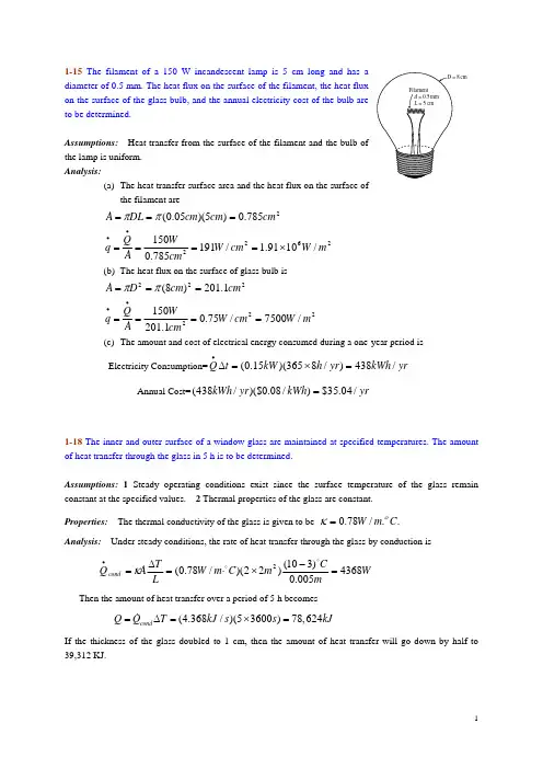
1-15 The filament of a 150 W incandescent lamp is 5 cm long and has a diameter of 0.5 mm. The heat flux on the surface of the filament, the heat flux on the surface of the glass bulb, and the annual electricity cost of the bulb are to be determined.Assumptions: Heat transfer from the surface of the filament and the bulb of the lamp is uniform. Analysis:(a) The heat transfer surface area and the heat flux on the surface ofthe filament are26222/1091.1/191785.0150785.0)5)(05.0(m W cm W cmW A Q q cm cm cm DL A ×=======••ππ(b) The heat flux on the surface of glass bulb is222222/7500/75.01.2011501.201)8(m W cm W cmW A Q q cm cm D A =======••ππ(c) The amount and cost of electrical energy consumed during a one-year period is Electricity Consumption=yr kWh yr h kW t Q /438)/8365)(15.0(=×=Δ•Annual Cost=yr kWh yr kWh /04.35$)/08.0)($/438(=1-18 The inner and outer surface of a window glass are maintained at specified temperatures. The amount of heat transfer through the glass in 5 h is to be determined.Assumptions: 1 Steady operating conditions exist since the surface temperature of the glass remain constant at the specified values. 2 Thermal properties of the glass are constant. Properties: The thermal conductivity of the glass is given to be../78.0C m W οκ=Analysis: Under steady conditions, the rate of heat transfer through the glass by conduction is W mC m C m W L T A Q cond4368005.0)310()22)(/78.0(2=−×⋅=Δ=•DDκThen the amount of heat transfer over a period of 5 h becomes(4.368/)(53600)78,624condQ Q T kJ s s kJ =Δ=×= If the thickness of the glass doubled to 1 cm, then the amount of heat transfer will go down by half to39,312 KJ.1-21 An electric resistance heating element is immersed in water initially at 20C D.The time it will take for this heater to raise the water temperature to 80C Das well as the convection heat transfer coefficients at the beginning and at the end of the heating process are to be determined.Assumptions: 1 Steady operating conditions exist and thus the rate of heat loss from the wire equals the rate of heat generation in the wire as a result of resistance heating. 2 Thermal properties of water are constant . 3 Heat losses from the water in the tank are negligible.Properties: The specific heat of water at room temperature is )9(/180.4−−⋅=A Table C kg kJ C D. Analysis: When steady operating conditions are reached, we have W E Q generated 800==••.This is also equal to the rate of heat gain by water. Noting that this is the only mechanism of energy transfer, the time it takes to raise the water temperature from 20C Dto80C Dis determined to be hs sJ CC kg J kg Q T T mC t T T mC t Q T T mC Q inin in 225.5810,18/800)2080)(/4180)(60()()()(121212==−⋅=−=Δ−=Δ−=••D DThe surface area of the wire is200785.0)5.0)(005.0()(m m m L D A ===ππThe Newton’s law of cooling for convection heat transfer is expressed as )(∞•−=T T hA Q S . Disregarding any heat transfer by radiation and thus assuming all the heat loss from the wire to occur by convection, the convection heat transfer coefficients at the beginning and at the end of the process are determined to beC m W Cm W T T A Q h C m W Cm W T T A Q h s s DDDD⋅=−=−=⋅=−=−=∞•∞•22222211/2550)80120)(00785.0(800)(/1020)20120)(00785.0(800)(Discussion: Note that a larger heat transfer coefficient is needed to dissipate heat through a smaller temperature difference for a specified heat transfer rate.1-25 A spacecraft in space absorbs solar radiation while losing heat to deep space by thermal radiation.The surface temperature of the spacecraft is to be determined when steady conditions are reached.Assumption : 1 Steady operating conditions exist since the surface temperature of the wall remain constant at the specified values. 2 Thermal properties of the wall are constant.Properties : The outer surface of a spacecraft has an emissivity of 0.8 and an absorptivity of 0.3.Analysis : When the heat loss from the outer surface of the spacecraft by radiation equals the solar radiation absorbed, the surface temperature can be determined from[]44428244)0()/1067.5(8.0)/950(3.0)(K T K m W A m W A T T A Q Q Q s space S solar radabsorbed solar −⋅×××=××−==−••−•εσαCanceling the surface area A and solving for S T gives K T s 54.281=1-26 The roof of a house with a gas furnace consists of a 15-cm thick concrete that is losing heat to the outdoors by radiation and convection .The rate of heat transfer through the roof is to determined.Assumptions: 1 Steady operating conditions exist. 2 The emissivity and thermal conductivity of the roof are constant.Properties: The thermal conductivity of the concrete is given to be 2/k W m C =⋅D. The emissivity of the outer surface of the roof is given to be 0.9.Analysis: In steady operation, heat transfer from the outer surface of the roof to the surroundings by convection and radiation must be equal to the heat transfer through the roof by conduction. That is,rad conv gs surroundin to roof cond roof Q Q Q +−−•••==,,The inner surface temperature of the roof is given to be C T in s D15,=.Letting out s T , denote the outer surface temperature of the roof, the energy balance above can be expressed as()()()()()()()(),,44,,,222,442824,()()15(2/)(300)0.1515/300100.9300 5.6710/273255s in s outs out surr s out surr s outs out s out T T Q kAh A T T A T T LC T Q W m C m mW m C m T Cm W m K T K K εσ••−−==−+−−=⋅=⋅−⎡⎤+×⋅+−⎣⎦D D DD DSolving the equation above using an equation solver (or by trial and error) givesW Q 450,25=•and C T out s D 64.8,=1-27 The backside of a thin metal plate is insulated, and the front side is exposed to solar radiation. The surface temperature of the plate is to be determined when steady operation is established.Assumptions: 1 Steady operating conditions exist. 2 Heat transfer through the insulated side of the plate is negligible. 3 The heat transfer coefficient is constant and uniform over the plate. 4 Radiation heat transfer is negligible.Properties: The solar absorptivity of the plate is given to be 6.0=α.Analysis: When the heat loss from the plate by convection equals the solar radiation absorbed, the surface temperature of the plate can be determined from()()()10/30/8007.022−⋅=××−==••−•s s solar convabsorbed solar T A C m W m W A T T hA Q Q Q D D αCanceling the surface area A and solving for s T gives C T s D7.28= be slightly above the interface temperature.。
第一章 绪论1. 列出5种使用ESA 和5种使用MSA 的分离操作。
答:属于ESA 分离操作的有精馏、萃取精馏、吸收蒸出、再沸蒸出、共沸精馏。
属于MSA 分离操作的有萃取精馏、液-液萃取、液-液萃取(双溶剂)、吸收、吸附。
2. 比较使用ESA 与MSA 分离方法的优缺点。
答:当被分离组分间相对挥发度很小,必须采用具有大量塔板数的精馏塔才能分离时,就要考虑采用萃取精馏(MSA ),但萃取精馏需要加入大量萃取剂,萃取剂的分离比较困难,需要消耗较多能量,因此,分离混合物优先选择能量媒介(ESA)方法。
3. 气体分离与渗透蒸发这两种膜分离过程有何区别?答:气体分离与渗透蒸发式两种正在开发应用中的膜技术。
气体分离更成熟些,渗透蒸发是有相变的膜分离过程,利用混合液体中不同组分在膜中溶解与扩散性能的差别而实现分离。
4. 海水的渗透压由下式近似计算:π=RTC/M ,式中C 为溶解盐的浓度,g/cm 3;M 为离子状态的各种溶剂的平均分子量。
若从含盐0.035 g/cm 3的海水中制取纯水,M=31.5,操作温度为298K 。
问反渗透膜两侧的最小压差应为多少kPa? 答:渗透压π=RTC/M =8.314×298×0.035/31.5=2.753kPa 。
所以反渗透膜两侧的最小压差应为2.753kPa 。
5. 假定有一绝热平衡闪蒸过程,所有变量表示在所附简图中。
求: (1) 总变更量数Nv;(2) 有关变更量的独立方程数Nc ; (3) 设计变量数Ni;(4) 固定和可调设计变量数Nx ,Na ;(5) 对典型的绝热闪蒸过程,你将推荐规定哪些变量?思路1:3股物流均视为单相物流, 总变量数Nv=3(C+2)=3c+6 独立方程数Nc 物料衡算式 C 个热量衡算式1个 ;相平衡组成关系式C个;1个平衡温度等式;1个平衡压力等式 共2C+3个;故设计变量F ziT F P FV , yi ,Tv , PvL , x i , T L , P L习题5附图Ni=Nv-Ni=3C+6-(2C+3)=C+3;固定设计变量Nx =C+2,加上节流后的压力,共C+3个 ;可调设计变量Na =0 解:(1) Nv = 3 ( c+2 )(2) Nc 物 c 能 1 相 c 内在(P ,T) 2 Nc = 2c+3 (3) Ni = Nv – Nc = c+3 (4) Nxu = ( c+2 )+1 = c+3 (5) Nau = c+3 – ( c+3 ) = 0 思路2:输出的两股物流看成是相平衡物流,所以总变量数Nv=2(C+2) 独立方程数Nc :物料衡算式 C 个 ,热量衡算式1个 ,共 C+1个 设计变量数 Ni=Nv-Ni=2C+4-(C+1)=C+3固定设计变量Nx:有 C+2个加上节流后的压力共C+3个 可调设计变量Na :有06. 满足下列要求而设计再沸汽提塔见附图,求: (1) 设计变更量数是多少? (2) 如果有,请指出哪些附加变量需要规定?解: N x u 进料 c+2压力 9 c+11=7+11=18N a u 串级单元 1 传热 1 合计 2 N V U = N x u +N a u = 20 附加变量:总理论板数。
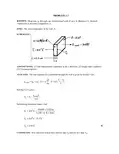
KNOWN: Heat rate, q, through one-dimensional wall of area A, thickness L, thermalconductivity k and inner temperature, T 1.FIND: The outer temperature of the wall, T 2.SCHEMATIC:ASSUMPTIONS: (1) One-dimensional conduction in the x-direction, (2) Steady-state conditions, (3) Constant properties.ANALYSIS: The rate equation for conduction through the wall is given by Fourier’s law,q q q A =-kdTdx A =kA T T Lcond x x 12==′′⋅⋅−. Solving for T 2 givesT T q L kA21cond =−.Substituting numerical values, findT C -3000W 0.025m0.2W /m K 10m 22=×⋅×415T C -37.5C 2=415 T C.2=378<COMMENTS: Note direction of heat flow and fact that T 2 must be less than T 1.KNOWN: Inner surface temperature and thermal conductivity of a concrete wall.FIND: Heat loss by conduction through the wall as a function of ambient air temperatures ranging from -15 to 38°C.SCHEMATIC:ASSUMPTIONS: (1) One-dimensional conduction in the x-direction, (2) Steady-state conditions, (3) Constant properties, (4) Outside wall temperature is that of the ambient air.ANALYSIS: From Fourier’s law, it is evident that the gradient, x dT dx q k ′′=−, is a constant, andhence the temperature distribution is linear, if xq ′′ and k are each constant. The heat flux must be constant under one-dimensional, steady-state conditions; and k is approximately constant if it depends only weakly on temperature. The heat flux and heat rate when the outside wall temperature is T 2 = -15°C are()212x 25C 15C dT T Tq k k 1W m K 133.3W m dx L 0.30m−−−′′=−==⋅= . (1)22x x q q A 133.3W m 20m 2667W ′′=×=×=. (2)<Combining Eqs. (1) and (2), the heat rate q x can be determined for the range of ambient temperature, -15 ≤ T 2 ≤ 38°C, with different wall thermal conductivities, k.-20-1010203040Ambient air temperature, T2 (C)-1500-500500150025003500H e a t l o s s , q x (W )Wall thermal conductivity, k = 1.25 W/m.K k = 1 W/m.K, concrete wall k = 0.75 W/m.KFor the concrete wall, k = 1 W/m ⋅K, the heat loss varies linearily from +2667 W to -867 W and is zero when the inside and ambient temperatures are the same. The magnitude of the heat rate increases with increasing thermal conductivity.COMMENTS: Without steady-state conditions and constant k, the temperature distribution in a plane wall would not be linear.PROBLEM 1.3KNOWN: Dimensions, thermal conductivity and surface temperatures of a concrete slab. Efficiency of gas furnace and cost of natural gas.FIND: Daily cost of heat loss. SCHEMATIC:ASSUMPTIONS: (1) Steady state, (2) One-dimensional conduction, (3) Constant properties.ANALYSIS: The rate of heat loss by conduction through the slab is()()12T T 7Cq k LW 1.4W /m K 11m 8m 4312W t 0.20m−°==⋅×=<The daily cost of natural gas that must be combusted to compensate for the heat loss is()()gd 6fq C 4312W $0.01/MJ C t 24h /d 3600s /h $4.14/d 0.910J /MJη×=∆=×=×<COMMENTS: The loss could be reduced by installing a floor covering with a layer of insulation between it and the concrete.KNOWN: Heat flux and surface temperatures associated with a wood slab of prescribed thickness.FIND: Thermal conductivity, k, of the wood.SCHEMATIC:ASSUMPTIONS: (1) One-dimensional conduction in the x-direction, (2) Steady-state conditions, (3) Constant properties.ANALYSIS: Subject to the foregoing assumptions, the thermal conductivity may be determined from Fourier’s law, Eq. 1.2. Rearranging,()L W 0.05mk=q 40T T m 40-20C x212′′=− k =0.10 W /m K.⋅<COMMENTS: Note that the °C or K temperature units may be used interchangeably whenevaluating a temperature difference.KNOWN: Inner and outer surface temperatures of a glass window of prescribed dimensions.FIND: Heat loss through window.SCHEMATIC:ASSUMPTIONS: (1) One-dimensional conduction in the x-direction, (2) Steady-state conditions, (3) Constant properties.ANALYSIS: Subject to the foregoing conditions the heat flux may be computed from Fourier’s law, Eq. 1.2.()T T q k L15-5CW q 1.4 m K 0.005mq 2800 W/m .12x x 2x −′′=′′=⋅′′=Since the heat flux is uniform over the surface, the heat loss (rate) isq = q x Aq = 2800 W /m 2 3m 2′′××q = 8400 W.<COMMENTS: A linear temperature distribution exists in the glass for the prescribedconditions.PROBLEM 1.6KNOWN: Width, height, thickness and thermal conductivity of a single pane window and the air space of a double pane window. Representative winter surface temperatures of single pane and air space.FIND: Heat loss through single and double pane windows.SCHEMATIC:ASSUMPTIONS: (1) One-dimensional conduction through glass or air, (2) Steady-state conditions, (3) Enclosed air of double pane window is stagnant (negligible buoyancy induced motion).ANALYSIS: From Fourier’s law, the heat losses areSingle Pane : ()T T 35 C 212q k A 1.4 W/m K 2m 19,600 W g g L 0.005m−==⋅=$Double Pane : ()T T 25 C 212q k A 0.0242m 120 W a a L 0.010 m−===$COMMENTS: Losses associated with a single pane are unacceptable and would remain excessive, even if the thickness of the glass were doubled to match that of the air space. The principal advantage of the double pane construction resides with the low thermal conductivity of air (~ 60 times smaller than that of glass). For a fixed ambient outside air temperature, use of the double pane construction would also increase the surface temperature of the glass exposed to the room (inside) air.PROBLEM 1.7KNOWN: Dimensions of freezer compartment. Inner and outer surface temperatures.FIND: Thickness of styrofoam insulation needed to maintain heat load below prescribed value.SCHEMATIC:ASSUMPTIONS: (1) Perfectly insulated bottom, (2) One-dimensional conduction through 5walls of area A = 4m 2, (3) Steady-state conditions, (4) Constant properties.ANALYSIS: Using Fourier’s law, Eq. 1.2, the heat rate isq = q A = kTLA total ′′⋅∆Solving for L and recognizing that A total = 5×W 2, findL =5 k T W q2∆()()5 0.03 W/m K 35 - -10 C 4m L =500 W2 ×⋅L = 0.054m = 54mm.<COMMENTS: The corners will cause local departures from one-dimensional conductionand a slightly larger heat loss.PROBLEM 1.8KNOWN: Dimensions and thermal conductivity of food/beverage container. Inner and outer surface temperatures.FIND: Heat flux through container wall and total heat load.SCHEMATIC:ASSUMPTIONS: (1) Steady-state conditions, (2) Negligible heat transfer through bottom wall, (3) Uniform surface temperatures and one-dimensional conduction through remaining walls.ANALYSIS: From Fourier’s law, Eq. 1.2, the heat flux is()0.023 W/m K 202CT T 221q k 16.6 W/m L 0.025 m⋅−−′′===$<Since the flux is uniform over each of the five walls through which heat is transferred, the heat load is ()q q A q H 2W 2W W W total 1212′′′′ =×=++×()()2q 16.6 W/m 0.6m 1.6m 1.2m 0.8m 0.6m 35.9 W =++×=<COMMENTS: The corners and edges of the container create local departures from one-dimensional conduction, which increase the heat load. However, for H, W 1, W 2 >> L, the effect is negligible.PROBLEM 1.9KNOWN: Masonry wall of known thermal conductivity has a heat rate which is 80% of that through a composite wall of prescribed thermal conductivity and thickness.FIND: Thickness of masonry wall.SCHEMATIC:ASSUMPTIONS: (1) Both walls subjected to same surface temperatures, (2) One-dimensional conduction, (3) Steady-state conditions, (4) Constant properties.ANALYSIS: For steady-state conditions, the conduction heat flux through a one-dimensional wall follows from Fourier’s law, Eq. 1.2,′′q = k TL∆where ∆T represents the difference in surface temperatures. Since ∆T is the same for both walls, it follows thatL = L k k q q 121221⋅′′′′.With the heat fluxes related as ′′=′′q 0.8 q 12L = 100mm 0.75 W /m K 0.25 W /m K 10.8= 375mm.1⋅⋅×<COMMENTS: Not knowing the temperature difference across the walls, we cannot find the value of the heat rate.PROBLEM 1.10KNOWN: Thickness, diameter and inner surface temperature of bottom of pan used to boil water. Rate of heat transfer to the pan.FIND: Outer surface temperature of pan for an aluminum and a copper bottom. SCHEMATIC:ASSUMPTIONS: (1) One-dimensional, steady-state conduction through bottom of pan. ANALYSIS: From Fourier’s law, the rate of heat transfer by conduction through the bottom of the pan isT T12q kAL−=Hence,qLT T12kA=+where ()222A D/40.2m/40.0314 m.ππ===Aluminum:()()600W0.005 mT110 C110.40 C12240 W/m K0.0314 m=+=⋅$$Copper:()()600W0.005 mT110 C110.25 C12390 W/m K0.0314 m=+=⋅$$COMMENTS: Although the temperature drop across the bottom is slightly larger for aluminum (due to its smaller thermal conductivity), it is sufficiently small to be negligible for both materials. To a good approximation, the bottom may be considered isothermal at T ≈110 °C, which is a desirable feature of pots and pans.PROBLEM 1.11KNOWN: Dimensions and thermal conductivity of a chip. Power dissipated on one surface.FIND: Temperature drop across the chip.SCHEMATIC:ASSUMPTIONS: (1) Steady-state conditions, (2) Constant properties, (3) Uniform heat dissipation, (4) Negligible heat loss from back and sides, (5) One-dimensional conduction in chip.ANALYSIS: All of the electrical power dissipated at the back surface of the chip is transferred by conduction through the chip. Hence, from Fourier’s law,P = q = kATt∆or()t P 0.001 m 4 W T =kW 150 W/m K 0.005 m 22⋅×∆=⋅∆T = 1.1 C. <COMMENTS: For fixed P, the temperature drop across the chip decreases with increasing k and W, as well as with decreasing t.PROBLEM 1.12KNOWN: Heat flux gage with thin-film thermocouples on upper and lower surfaces; output voltage, calibration constant, thickness and thermal conductivity of gage.FIND: (a) Heat flux, (b) Precaution when sandwiching gage between two materials.SCHEMATIC:ASSUMPTIONS: (1) Steady-state conditions, (2) One-dimensional heat conduction in gage, (3) Constant properties.ANALYSIS: (a) Fourier’s law applied to the gage can be written as′′q = kTx∆∆ and the gradient can be expressed as∆∆∆T x = E /N S AB twhere N is the number of differentially connected thermocouple junctions, S AB is the Seebeckcoefficient for type K thermocouples (A-chromel and B-alumel), and ∆x = t is the gage thickness. Hence,′′q =k ENS AB t∆′′⋅××××××q = 1.4 W /m K 35010-6 V54010-6 V /C 0.2510-3 m= 9800 W /m 2$. <(b) T he major precaution to be taken with this type of gage is to match its thermalconductivity with that of the material on which it is installed. If the gage is bondedbetween laminates (see sketch above) and its thermal conductivity is significantly different from that of the laminates, one dimensional heat flow will be disturbed and the gage will read incorrectly.COMMENTS: If the thermal conductivity of the gage is lower than that of the laminates, will it indicate heat fluxes that are systematically high or low?PROBLEM 1.13KNOWN: Hand experiencing convection heat transfer with moving air and water.FIND: Determine which condition feels colder. Contrast these results with a heat loss of 30 W/m 2 under normal room conditions.SCHEMATIC:ASSUMPTIONS: (1) Temperature is uniform over the hand’s surface, (2) Convection coefficient is uniform over the hand, and (3) Negligible radiation exchange between hand and surroundings in the case of air flow.ANALYSIS: The hand will feel colder for the condition which results in the larger heat loss. The heat loss can be determined from Newton’s law of cooling, Eq. 1.3a, written as()s q h T T ∞′′=−For the air stream:()22air q 40W m K 305K 1,400W m ′′ =⋅−−=<For the water stream:()22water q 900W m K 3010K 18,000W m ′′=⋅−=<COMMENTS: The heat loss for the hand in the water stream is an order of magnitude larger than when in the air stream for the given temperature and convection coefficient conditions. In contrast, the heat loss in a normal room environment is only 30 W/m 2 which is a factor of 400 times less than the loss in the air stream. In the room environment, the hand would feel comfortable; in the air and water streams, as you probably know from experience, the hand would feel uncomfortably cold since the heat loss is excessively high.PROBLEM 1.14KNOWN: Power required to maintain the surface temperature of a long, 25-mm diameter cylinder with an imbedded electrical heater for different air velocities.FIND: (a) Determine the convection coefficient for each of the air velocity conditions and display the results graphically, and (b) Assuming that the convection coefficient depends upon air velocity as h = CV n, determine the parameters C and n.SCHEMATIC:V(m/s) 1 2 4 8 12′P e(W/m) 450 658 983 1507 1963h (W/m2⋅K) 22.0 32.2 48.1 73.8 96.1 ASSUMPTIONS: (1) Temperature is uniform over the cylinder surface, (2) Negligible radiationexchange between the cylinder surface and the surroundings, (3) Steady-state conditions.ANALYSIS: (a) From an overall energy balance on the cylinder, the power dissipated by theelectrical heater is transferred by convection to the air stream. Using Newtons law of cooling on a perunit length basis,()()e sP h D T Tπ∞′=−where e P′ is the electrical power dissipated per unit length of the cylinder. For the V = 1 m/s condition, using the data from the table above, find()2h450W m0.025m30040C22.0W m Kπ=×−=⋅<Repeating the calculations, find the convection coefficients for the remaining conditions which are tabulated above and plotted below. Note that h is not linear with respect to the air velocity.(b) To determine the (C,n) parameters, we plotted h vs. V on log-log coordinates. Choosing C =22.12 W/m2⋅K(s/m)n, assuring a match at V = 1, we can readily find the exponent n from the slope ofthe h vs. V curve. From the trials with n = 0.8, 0.6 and 0.5, we recognize that n = 0.6 is a reasonable choice. Hence, C = 22.12 and n = 0.6. <024681012Air velocity, V (m/s)20406080100Coefficient,h(W/m^2.K)Data, smooth curve, 5-points1246810Air velocity, V (m/s)1020406080100Coefficient,h(W/m^2.K)Data , smooth curve, 5 pointsh = C * V^n, C = 22.1, n = 0.5n = 0.6n = 0.8PROBLEM 1.15KNOWN: Long, 30mm-diameter cylinder with embedded electrical heater; power required to maintain a specified surface temperature for water and air flows.FIND: Convection coefficients for the water and air flow convection processes, h w and h a ,respectively.SCHEMATIC:ASSUMPTIONS: (1) Flow is cross-wise over cylinder which is very long in the direction normal to flow.ANALYSIS: The convection heat rate from the cylinder per unit length of the cylinder has the form()()q = h D T T s π′−∞and solving for the heat transfer convection coefficient, find()q h =.D T T s π′−∞Substituting numerical values for the water and air situations:Water()28 10 W/mh == 4,570 W/m K0.030m 90-25 C32w π×⋅× <Air()400 W/mh = 65 W/m K.0.030m 90-25 C2a π=⋅× <COMMENTS: Note that the air velocity is 10 times that of the water flow, yeth w ≈ 70 × h a .These values for the convection coefficient are typical for forced convection heat transfer withliquids and gases. See Table 1.1.PROBLEM 1.16KNOWN: Dimensions of a cartridge heater. Heater power. Convection coefficients in air and water at a prescribed temperature.FIND: Heater surface temperatures in water and air.SCHEMATIC:ASSUMPTIONS: (1) Steady-state conditions, (2) All of the electrical power is transferred to the fluid by convection, (3) Negligible heat transfer from ends.ANALYSIS: With P = q conv , Newton’s law of cooling yields ()()P=hA T T h DL T T PT T .h DLs s s ππ−=−=+∞∞∞In water,T C +2000 W5000 W /m K 0.02 m 0.200 ms 2=⋅×××20 πT C +31.8C =51.8C.s =20 <In air,T C +2000 W50 W /m K 0.02 m 0.200 ms 2=⋅×××20 πT C +3183C =3203C.s =20 <COMMENTS: (1) Air is much less effective than water as a heat transfer fluid. Hence, the cartridge temperature is much higher in air, so high, in fact, that the cartridge would melt.(2) In air, the high cartridge temperature would render radiation significant.PROBLEM 1.17KNOWN: Length, diameter and calibration of a hot wire anemometer. Temperature of air stream. Current, voltage drop and surface temperature of wire for a particular application.FIND: Air velocitySCHEMATIC:ASSUMPTIONS: (1) Steady-state conditions, (2) Negligible heat transfer from the wire by natural convection or radiation.ANALYSIS: If all of the electric energy is transferred by convection to the air, the following equality must be satisfied ()P EI hA T T elec s ==−∞where ()52A DL 0.0005m 0.02m 3.1410m .ππ−==×=×Hence, ()()EI 5V 0.1A2h 318 W/m K 52A T T s 3.1410m 50 C×===⋅−−∞×$()25252V 6.2510h 6.2510318 W/m K 6.3 m/s −−=×=×⋅=<COMMENTS: The convection coefficient is sufficiently large to render buoyancy (natural convection) and radiation effects negligible.PROBLEM 1.18KNOWN: Chip width and maximum allowable temperature. Coolant conditions.FIND: Maximum allowable chip power for air and liquid coolants.SCHEMATIC:ASSUMPTIONS: (1) Steady-state conditions, (2) Negligible heat transfer from sides and bottom, (3) Chip is at a uniform temperature (isothermal), (4) Negligible heat transfer by radiation in air.ANALYSIS: All of the electrical power dissipated in the chip is transferred by convection to the coolant. Hence,P = qand from Newton’s law of cooling,P = hA(T - T∞) = h W2(T - T∞).In air,P max = 200 W/m2⋅K(0.005 m)2(85 - 15) ° C = 0.35 W. < In the dielectric liquidP max = 3000 W/m2⋅K(0.005 m)2(85-15) ° C = 5.25 W. < COMMENTS: Relative to liquids, air is a poor heat transfer fluid. Hence, in air the chip can dissipate far less energy than in the dielectric liquid.PROBLEM 1.19KNOWN: Length, diameter and maximum allowable surface temperature of a power transistor. Temperature and convection coefficient for air cooling.FIND: Maximum allowable power dissipation.SCHEMATIC:ASSUMPTIONS: (1) Steady-state conditions, (2) Negligible heat transfer through base of transistor, (3) Negligible heat transfer by radiation from surface of transistor.ANALYSIS: Subject to the foregoing assumptions, the power dissipated by the transistor is equivalent to the rate at which heat is transferred by convection to the air. Hence, ()P q hA T T elec conv s ==−∞where ()()2242A DL D /40.012m 0.01m 0.012m /4 4.9010m .ππ− =+=×+=×For a maximum allowable surface temperature of 85°C, the power is()()242P 100 W/m K 4.9010m 8525C 2.94 W elec −=⋅×−=$ <COMMENTS: (1) For the prescribed surface temperature and convection coefficient, radiation will be negligible relative to convection. However, conduction through the base could be significant, thereby permitting operation at a larger power.(2) The local convection coefficient varies over the surface, and hot spots could exist if there are locations at which the local value of h is substantially smaller than the prescribed average value.PROBLEM 1.20KNOWN: Air jet impingement is an effective means of cooling logic chips.FIND: Procedure for measuring convection coefficients associated with a 10 mm × 10 mm chip.SCHEMATIC:ASSUMPTIONS: Steady-state conditions.ANALYSIS: One approach would be to use the actual chip-substrate system, Case (a), to perform the measurements. In this case, the electric power dissipated in the chip would be transferred from the chip by radiation and conduction (to the substrate), as well as by convection to the jet. An energy balance for the chip yields elec conv cond rad q q q q =++. Hence, with ()conv s q hA T T ∞=−, where A = 100mm 2 is the surface area of the chip,()elec cond rad s q q q h A T T ∞−−=− (1)While the electric power (q elec ) and the jet (T ∞) and surface (T s ) temperatures may be measured, losses from the chip by conduction and radiation would have to be estimated. Unless the losses are negligible (an unlikely condition), the accuracy of the procedure could be compromised by uncertainties associated with determining the conduction and radiation losses. A second approach, Case (b), could involve fabrication of a heater assembly for which theconduction and radiation losses are controlled and minimized. A 10 mm × 10 mm copper block (k ~ 400 W/m ⋅K) could be inserted in a poorly conducting substrate (k < 0.1 W/m ⋅K) and a patch heater could be applied to the back of the block and insulated from below. If conduction to both the substrate andinsulation could thereby be rendered negligible, heat would be transferred almost exclusively through the block. If radiation were rendered negligible by applying a low emissivity coating (ε < 0.1) to the surface of the copper block, virtually all of the heat would be transferred by convection to the jet. Hence, q cond and q rad may be neglected in equation (1), and the expression may be used to accurately determine h from the known (A) and measured (q elec , T s , T ∞) quantities.COMMENTS: Since convection coefficients associated with gas flows are generally small, concurrent heat transfer by radiation and/or conduction must often be considered. However, jet impingement is one of the more effective means of transferring heat by convection and convection coefficients well in excess of 100 W/m 2⋅K may be achieved.PROBLEM 1.21KNOWN: Upper temperature set point, T set , of a bimetallic switch and convection heat transfer coefficient between clothes dryer air and exposed surface of switch.FIND: Electrical power for heater to maintain T set when air temperature is T ∞ = 50°C.SCHEMATIC:ASSUMPTIONS: (1) Steady-state conditions, (2) Electrical heater is perfectly insulated from dryer wall, (3) Heater and switch are isothermal at T set , (4) Negligible heat transfer from sides of heater or switch, (5) Switch surface, A s , loses heat only by convection.ANALYSIS: Define a control volume around the bimetallic switch which experiences heat input from the heater and convection heat transfer to the dryer air. That is,()E -E = 0q - hA T T 0.out in s set elec −=∞ The electrical power required is,()q = hA T T s set elec −∞()q = 25 W/m K 3010 m 7050K=15 mW.2-62elec ⋅××−<COMMENTS: (1) This type of controller can achieve variable operating air temperatureswith a single set-point, inexpensive, bimetallic-thermostatic switch by adjusting power levels to the heater.(2) Will the heater power requirement increase or decrease if the insulation pad is other than perfect?PROBLEM 1.22KNOWN: Hot vertical plate suspended in cool, still air. Change in plate temperature with time at the instant when the plate temperature is 225°C.FIND: Convection heat transfer coefficient for this condition.SCHEMATIC:ASSUMPTIONS: (1) Plate is isothermal and of uniform temperature, (2) Negligible radiation exchange with surroundings, (3) Negligible heat lost through suspension wires.ANALYSIS: As shown in the cooling curve above, the plate temperature decreases with time. The condition of interest is for time t o . For a control surface about the plate, the conservation of energy requirement is()E -E = E dT2hA T T Mc dtout st in s s p−−=∞where A s is the surface area of one side of the plate. Solving for h, find()Mc dTh=2A T T dt ps s −∞()()3.75 kg 2770 J/kg K h=0.022 K/s=6.4 W/m K20.30.3m 22525K22×⋅×⋅××−<COMMENTS: (1) Assuming the plate is very highly polished with emissivity of 0.08, determine whether radiation exchange with the surroundings at 25°C is negligible compared to convection.(2) We will later consider the criterion for determining whether the isothermal plate assumption is reasonable. If the thermal conductivity of the present plate were high (such as aluminum or copper),the criterion would be satisfied.PROBLEM 1.23KNOWN: Width, input power and efficiency of a transmission. Temperature and convection coefficient associated with air flow over the casing.FIND: Surface temperature of casing. SCHEMATIC:ASSUMPTIONS: (1) Steady state, (2) Uniform convection coefficient and surface temperature, (3) Negligible radiation.ANALYSIS: From Newton’s law of cooling,()()2s s s q hA T T 6hW T T ∞∞=−=−where the output power is η P i and the heat rate is()i o i q P P P 1150hp 746W /hp 0.077833W η=−=−=××=Hence,()s 222q 7833WT T 30C 102.5C 6hW 6200W /m K 0.3m ∞=+=°+=°×⋅×<COMMENTS: There will, in fact, be considerable variability of the local convection coefficient over the transmission case and the prescribed value represents an average over the surface.PROBLEM 1.24KNOWN: Air and wall temperatures of a room. Surface temperature, convection coefficient and emissivity of a person in the room.FIND: Basis for difference in comfort level between summer and winter.SCHEMATIC:ASSUMPTIONS: (1) Person may be approximated as a small object in a large enclosure.ANALYSIS: Thermal comfort is linked to heat loss from the human body, and a chilled feeling is associated with excessive heat loss. Because the temperature of the room air is fixed, the different summer and winter comfort levels can not be attributed to convection heat transfer from the body. In both cases, the heat flux isSummer and Winter : ()22q h T T 2 W/m K 12 C 24 W/m conv s ′′=−=⋅×=∞$However, the heat flux due to radiation will differ, with values of Summer : ()()448244442q T T 0.9 5.6710W/m K 305300K 28.3 W/m rads sur εσ−′′=−=××⋅−=Winter : ()()448244442q T T 0.9 5.6710W/m K 305287K 95.4 W/m rad s sur εσ−′′=−=××⋅−=There is a significant difference between winter and summer radiation fluxes, and the chilled condition is attributable to the effect of the colder walls on radiation.COMMENTS: For a representative surface area of A = 1.5 m 2, the heat losses are q conv = 36 W, q rad(summer) = 42.5 W and q rad(winter) = 143.1 W. The winter time radiation loss is significant and if maintained over a 24 h period would amount to 2,950 kcal.PROBLEM 1.25KNOWN: Diameter and emissivity of spherical interplanetary probe. Power dissipation within probe.FIND: Probe surface temperature.SCHEMATIC:ASSUMPTIONS: (1) Steady-state conditions, (2) Negligible radiation incident on the probe.ANALYSIS: Conservation of energy dictates a balance between energy generation within the probe and radiation emission from the probe surface. Hence, at any instant-E + E = 0out g εσA T E s s 4g = E T D 1/4g s 2επσ =()150W T 0.80.5 m 5.67101/4s 2824 W/m K π=× −⋅T K.s =2547.<COMMENTS: Incident radiation, as, for example, from the sun, would increase the surfacetemperature.。
传质与分离课后练习题一、填空题1. 传质过程主要包括________、________和________三种基本方式。
2. 在气体吸收过程中,根据溶质与溶剂的接触方式,可分为________和________两种类型。
3. 蒸馏操作中,将混合液加热至沸腾,产生的蒸汽通过________冷却后,可得到纯净的液体。
4. 萃取过程中,常用的萃取剂应具备________、________和________等特点。
5. 吸附分离技术中,根据吸附剂与吸附质之间的作用力,可分为________和________两种类型。
二、选择题1. 下列哪种传质方式属于质量传递?()A. 动量传递B. 能量传递C. 质量传递D. 热量传递2. 在下列吸收操作中,属于物理吸收的是()。
A. 氨气吸收B. 二氧化硫吸收C. 丙酮吸收D. 氯气吸收3. 下列哪种蒸馏方法适用于分离沸点相近的液体混合物?()A. 简单蒸馏B. 蒸馏C. 蒸馏D. 分子蒸馏A. 萃取剂的性质B. 混合液的温度C. 萃取剂的浓度5. 下列哪种吸附剂属于物理吸附剂?()A. 活性炭B. 离子交换树脂C. 氢氧化钠D. 氧化铝三、判断题1. 传质过程中,质量传递速率与浓度梯度成正比。
()2. 在气体吸收过程中,气膜控制表示溶质在气相中的扩散速率较慢。
()3. 蒸馏过程中,塔板数越多,分离效果越好。
()4. 萃取操作中,萃取剂的选择对萃取效果具有重要影响。
()5. 吸附分离过程中,吸附剂的选择与吸附质的性质无关。
()四、简答题1. 简述传质过程的基本原理。
2. 请列举三种常见的气体吸收设备,并简要说明其工作原理。
3. 蒸馏操作中,如何提高塔板的效率?4. 萃取过程中,影响萃取效果的因素有哪些?5. 简述吸附分离技术的应用领域。
五、计算题1. 某混合液中含有甲、乙两种组分,其摩尔分数分别为0.4和0.6。
现将该混合液进行蒸馏分离,求在塔顶和塔底得到的馏分中甲、乙组分的摩尔分数。
第一章传质过程基础一、选择与填空(30分,每空2分)1.传质通量与相对应。
A Q/q ;B C/_4 .C C.jft .D C A2.传质通量j,\与相对应。
A.C M("・*):B.5“:C.C/村;D. P^A■:3.传质通量七"与相对应。
A C A(U A-U M);B.C^A. c. %*; D.力%4.等分了反方向扩散通常发生在单元操作过程中:-•组分通过另-•停滞组分的扩散通常发生在单元操作过程中。
5.描述动量和质量传递类似律的一层模型是:两层模型是;三层模型是。
I.在根管子中存在有由CHA组分A)和Hc(组分B)组成的气体混合物,压力为1.013x10⁵Pa、温度为298K。
已知管内的CH4通过停滞的He进行稳态维扩散,在相距0.02m的两端,CH4的分压分别为= 6 7 8 08x1 °4 Pa及2.03x10* pa,管内的总压维持恒定。
扩散条件下,CH,在He中的扩散系数为= 675x10-5 m2/s。
试求算CH4的传质通量、。
2.298 K的水以0.5 m/s的主体流速流过内径为25mm的荼管,2知荼溶于水时的施密特数衣为2330,试分别用雷诺、普兰德一泰勒、卡门和柯尔本类比关系式求算充分发展后的对流传质系数。
三、推导(30分,每题15分)1.对于A、B二组元物系,试采用欧拉(Euler)方法,推导沿x、y方向进行二维分了传二、计算(40分,每20分)质时的传质微分方程。
设系统内发生化学反应,组分A的质量生成速率为〜kg/(m3・s)2.试利用传质速率方程和扩散通量方程,将稣转换成片。
6 通常,气体的扩散系数与有关,液体的扩散系数与有关。
7 '表示对流传质系数,取表示对流传质系数,它们之间的关系是o8 对流传质系数与与推动力相对应。
A."B.C.D.矶。
9.推动力与对流传质系数相对应。
A.知;B.匕;C.电;D.。
化工传递过程基础复习题(2009)1.何为“连续介质假定”,这一假定的要点和重要意义是什么?试解释联续性方程的物理意义。

传质分离过程习题答案(总65页)--本页仅作为文档封面,使用时请直接删除即可----内页可以根据需求调整合适字体及大小--第二章习题1. 计算在和下苯(1)-甲苯(2)-对二甲苯(3)三元系,当x 1 = 、x 2 =、x 3 =时的K 值。
汽相为理想气体,液相为非理想溶液。
并与完全理想系的 K 值比较。
已知三个二元系的wilson 方程参数(单位: J/mol ): λ12-λ11=-; λ12-λ22= λ23-λ22=; λ23-λ33=- λ13-λ11=; λ13-λ33=-在T = K 时液相摩尔体积(m 3/kmol )为:=×10 -3 ;=×10 -3 ;=×10 -3安托尼公式为(p s :Pa ; T :K ): 苯:1n =(); 甲苯:1n=();对 -二甲苯:1n= ();解:由Wilson 方程得:Λ12=l l V V 12exp[-(λ12-λ11)/RT]=331091.1001055.177⨯⨯×exp[-/×]=Λ21= Λ13= Λ31= Λ23= Λ32= ln γ1=1-ln (Λ12X 2+Λ13X 3)-[3322311313233221122131321211X X X X X X X X X X X X +Λ+ΛΛ+Λ++ΛA +Λ+Λ+] =γ1=同理,γ2=; γ3= lnP 1S = P 1S = lnP 2S = P 2S = lnP 3S = P 3S =作为理想气体实际溶液,K 1=P P S11γ=, K 2=, K 3= 若完全为理想系,K 1=P P S1= K 2= K 3=2. 在361K 和下,甲烷和正丁烷二元系呈汽液平衡,汽相含甲烷%( mol ),与其平衡的液相含甲烷%。
用R -K 方程计算和Ki 值。
解:a 11=115.2242748.0c c p T R ⨯= • dm 6 • • mol -2a 22=225.2242748.0c c p T R ⨯= MPa•dm 6••mol -2b 1=11208664.0c c p T R ⨯= dm 3mol -1b 2=225.2242748.0c c p T R ⨯= dm 3mol -1 其中T c1=, P c1= T c2=, P c2=均为查表所得。
第十章1. 在一根管子中存在有由CH 4(组分A )和He (组分B )组成的气体混合物,压力为1.013×10⁵ Pa 、温度为298K 。
已知管内的CH 4通过停滞的He 进行稳态一维扩散,在相距0.02m 的两端,CH 4的分压分别为411008.6⨯=A p Pa 及421003.2⨯=A p Pa ,管内的总压维持恒定。
试求(1) CH 4相对于摩尔平均速度m u 的扩散通量A J ; (2) CH 4相对于静止坐标的通量A N 。
已知CH 4~He 系统在1.013×10⁵ Pa 和298K 时的扩散系数410675.0-⨯=AB D m 2/s 。
解:(1) )(21A A ABA p p zRT D J -∆=44540.67510(6.0810 2.0310) 5.521083142980.02--⨯=⨯⨯-⨯=⨯⨯⨯kmol/(m 2·s)(2) BMAA A BM AB A p pJ p p p p z RT D N =-∆=)(21 12211212ln ln A A A A B B B B BM p p p p p p p p p p p ---=-=445454410846.51008.610013.11003.210013.1ln1003.21008.6⨯=⨯-⨯⨯-⨯⨯-⨯=Pa545510565.910846.510013.11052.5--⨯=⨯⨯⨯⨯=A N kmol/(m 2·s)2. 将温度为298K 、压力为1atm 的He 和N 2的混合气体,装在一直径为5mm 、长度为0.1 m 的管中进行等分子反方向扩散,已知管子两端He 的压力分别为0.06atm 和0.02atm ,在上述条件下扩散系数410687.02--⨯=N He D m 2/s ,试求(1) He 的扩散通量; (2) N 2的扩散通量;(3) 在管的中点截面上的He 和N 2分压。

7、传质分离过程一、填空题1.依据分离原理的不同,传质分离过程可分为和两大类。
2.分子传质是指 ,描述分子传质的基本方程为 .3.对流传质是指 ,描述对流传质的基本方程为 .4.双膜模型的模型参数为和 .5.在板式塔中,气液两相接触,两相组成沿塔高呈变化,在正常操作下, 为连续相, 为分散相.6.在填料塔中,气液两相接触,两相组成沿塔高呈变化,在 正常操作下, 为连续相, 为分散相.二、选择题1.气体的吸收属于( );液体的精馏属于( );液体的萃取属于( );固体的干燥属于().A.汽液传质,B.气液传质,C.液液传质,D.气固传质过程.2.某含乙醇12.5%(质量分数)的乙醇水溶液,其所含乙醇的摩尔比( )A.0.143;B.0.0559;C.0.0502;D.0.0529.3.在平衡分离过程中,i和j两组分的分离因子a ij越大,则表明该两 组分( )分离.A.越容易;B.越不容易;C.不能够.4.在分子传质过程中,若漂流因素p总/p BM>1,则组分A的传质通量N A与组分A的扩散通量J A的关系为()A. N A=J A;B. N A<J A;C. N A>J A;D.不好确定. 5.气体中的扩散系数D AB与温度T的关系为( )A. D AB∝T1.0;B.D AB∝T0.5;C.D AB∝T2.0;D.D AB∝T1.75.6.气体中的扩散系数D AB与压力p总的关系为( )A.D AB∝p总1.5;B.D AB∝p总1.0;C. D AB∝p总0.5;D.D AB∝p总.-1.0三、计算题1、在某一细管底部装有温度为30°C的水.总压为101.3kPa,相同温度的干空气从细管顶部流过,水向干空气中蒸发.水蒸气在管内的扩散距离(由液面至顶部)为25cm.在101.3kPa和0°C条件下,水蒸气在空 气中的扩散系数为0.22´10-4m2/s,水在30°C时的蒸汽压为4.24kPa.试 计算定态扩散时水蒸气的传质通量N A.(参考书中例题7-3)解:2、在直径为0.015m长度为0.52m的圆管中CO2气体通过N2进行稳态分子扩散.管内N2的温度为383K,总压为158.6kPa,管两端CO2的分压分别为95kPa和12kPa.试计算CO2的扩散通量.已知298K、101.3kPa下CO2在N2中的扩散系数为0.167´10-4m2/s解:8、吸收课堂练习• 一、填空题1.若溶质在气相中的组成以分压p、液相组成以摩尔分数x表示, 则亨利定律的表达式为 ,E称为 .若E值增大,说明2. K Y和K G的关系是 ,k x与k L的关系是 .3.若c*-c»c i-c,则该过程为控制, 若p-p*»p-p i,4.气相总阻力方程可表示为1=1+1,其中1表示 ,K G k G 1Hk L k G当H 时可忽略,则该吸收过程称为气膜控制.HkL5.增加吸收剂用量,操作线的斜 (增大、减小、不变),吸收推动力 (增大、减小、不变).6.填料塔的流体力学性能常用曲线表示,该曲线上有两个 折点,他们分别是和 .二、选择题1、对接近常压的低组成溶质的气液平衡系统,当温度升高时,亨利系数E将( ),相平衡常数m将( ),溶解度系数H将( )。
第5章 传质过程及塔设备气体的吸收1.空气和CO 2的混合气体中,CO 2的体积分数为20%,求其摩尔分数y 和摩尔比Y 各为多少解 因摩尔分数=体积分数,.02y =摩尔分数 摩尔比 ..020251102y Y y ===--. 2. 20℃的l00g 水中溶解lgNH 3, NH 3在溶液中的组成用摩尔分数x 、浓度c 及摩尔比X 表示时,各为多少解 摩尔分数//117=0.010*******/18x =+浓度c 的计算20℃,溶液的密度用水的密度./39982s kg m ρ=代替; 溶液中NH 3的量为 /311017n kmol -=⨯ 溶液的体积 /.33101109982 V m -=⨯ 溶液中NH 3的浓度//.33311017==0.581/101109982n c kmol m V --⨯=⨯ 或 . 3998200105058218s sc x kmol m M ρ==⨯=../ NH 3与水的摩尔比的计算 或 ..00105001061100105x X x ===--. 3.进入吸收器的混合气体中,NH 3的体积分数为10%,吸收率为90%,求离开吸收器时NH 3的组成,以摩尔比Y 和摩尔分数y 表示;吸收率的定义为解 原料气中NH 3的摩尔分数0.1y = 摩尔比 (11101)01111101y Y y ===-- 吸收器出口混合气中NH 3的摩尔比为摩尔分数 (22200111)=0010981100111Y y Y ==++ 00g 水中溶解lg 3 NH ,查得20℃时溶液上方3NH 的平衡分压为798Pa;此稀溶液的气液相平衡关系服从亨利定律,试求亨利系数E 单位为kPa 、溶解度系数H 单位为/()3kmol m kPa ⋅和相平衡常数m;总压为100kPa ;解 液相中3NH 的摩尔分数/.//1170010511710018x ==+气相中3NH 的平衡分压 *.0798 P kPa=亨利系数 *./.0798*******E p x ===/液相中3NH 的浓度 /./.333110170581 101109982n c kmol m V --⨯===⨯/ 溶解度系数 /*./../()3058107980728H c p kmol m kPa ===⋅ 液相中3NH 的摩尔分数 //1170010511710018x ==+./气相的平衡摩尔分数 **.0798100y p p ==// 相平衡常数 * (0798)07610000105y m x===⨯或 //.76100076m E p ===5. 10℃时氧在水中的溶解度表达式为*.6331310p x =⨯,式中*p 为氧在气相中的平衡分压,单位为kPa x ;为溶液中氧的摩尔分数;试求总压为.101325kPa ,温度为10℃时,31m 水中最大可能溶解多少克氧空气中氧的体积分数为21%.解 总压.101325 p kPa =空气中2O 的压力分数 .021A p p ==/体积分数 空气中2O 的分压 *..021101325 A p kPa =⨯ 亨利系数 .6331310E kPa =⨯ 1 利用亨利定律*A p Ex =计算与气相分压..021101325A p kPa =⨯相平衡的液相组成为*. ..62602110132564210 331310A p x kmol O kmol E ⨯===⨯⨯./溶液 此为1kmol 水溶液中最大可能溶解.6264210kmol O -⨯ 因为溶液很稀,其中溶质很少1kmol 水溶液≈1kmol 水=18 kg水10℃,水的密度 .39997kg m ρ=/ 故 1kmol 水溶液≈.3189997m /水 即.3189997m 水中最大可能溶解.664210kmol -⨯氧故 31m 水中最大可能溶解的氧量为 2 利用亨利定律*A A c p H=计算31m 水中最大可能溶解的氧量为*(..)(.).5432021101325 16761035710A A c p H kmol O m --==⨯⨯=⨯/ 溶液 7. 用清水吸收混合气中的NH 3,进入吸收塔的混合气中,含NH 3体积分数为6%,吸收后混合气中含NH 3的体积分数为%,出口溶液的摩尔比为30012 kmol NH kmol ./水;此物系的平衡关系为*.076Y X =;气液逆流流动,试求塔顶、塔底的气相传质推动力各为多少解 已知.1006y =,则()/./..111100609400638Y y y =-== 已知.20004y =,则()./..32000410004=40210Y =-⨯ 已知10.012X =,则*10.760.0120.00912Y =⨯= 已知20X =,则*20Y =塔顶气相推动力 *3222 4.0210=Y Y Y -∆=-⨯塔底气相推动力 *1110.06380.009120.0547Y Y Y ∆=-=-=分压力为50kPa 的混合气体,分别与CO 2浓度为./3001kmol m 的水溶液和CO 2浓度为.3005kmol m /的水溶液接触;物系温度均为25℃,气液相平衡关系*.5166210p xkPa =⨯;试求上述两种情况下两相的推动力分别以气相分压力差和液相浓度差表示,并说明CO 2在两种情况下属于吸收还是解吸;解 温度25℃t =,水的密度为/3s 997kg m ρ= 混合气中CO 2的分压为50p kPa = 水溶液的总浓度/39718s sc kmol m M ρ≈=水溶液 1 以气相分压差表示的吸收推动力 ①液相中CO 2的浓度 .32001 A c kmol CO m =/水溶液 液相中CO 2的摩尔分数././4001=180********A x c c -==⨯ 与液相平衡的气相平衡分压为气相分压差表示的推动力 *503020p p p kPa ∆=-=-=吸收 ② 液相中CO 2的浓度30.05kmol m /A c =水溶液 液相中CO 2的摩尔分数40.05/9.02710997/18A x c c -===⨯ 与液相平衡的气相平衡分压为气相分压差表示的推动力 *15050100p p p kPa ∆=-=-= 解吸 2 以液相浓度差表示的吸收推动力 与气相250CO p kPa =分压平衡的液相组成为 平衡的液相浓度①液相中CO 2的浓度./32001 A c kmol CO m =水溶液 液相浓度差表示的推动力为*...3001666001000666kmol /m A A c c c ∆=-=-= 吸收②液相中CO 2的浓度320.05 CO /A c kmol m =水溶液液相浓度差表示的推动力为*.../300500166600333A A c c c kmol m ∆=-=-= 解吸10. 混合气含CO 2体积分数为10%,其余为空气;在30℃、2MPa 下用水吸收,使CO 2的体积分数降到%,水溶液出口组成41610X -=⨯摩尔比;混合气体处理量为/32240m h 按标准状态,.,27315 101325K Pa ,塔径为1.5m;亨利系数188E MPa =,液相体积总传质系数(/)3350L K a kmol m h kmol m ⋅=⋅⋅,;试求每小时用水量及填料塔的填料层高度;解 1用水量计算....,...3112 2 010005010111000550310090995y Y Y Y -======⨯,,.,41610X -=⨯,20X = 混合气流量 2240'10022.4G kmol h ==/惰性气体流量 ()()G G 'y .kmol h 1110010190=-=-=/ 用水量 G(Y Y )(..)L .kmol /h X X 41241290011100050315910610----===⨯-⨯2 填料层高度Z 计算水溶液的总浓度 /././3995718553s s c M kmol m ρ≈== 体积传质系数 ./()3553502765 X L K a cK a kmol m h ==⨯=⋅ 液相总传质单元高度 .(.)42159102765154OLX L H K a Ωπ⨯==⨯⨯①对数平均推动力法计算OL N气液相平衡常数188942E m p=== 液相总传质单元数 ②吸收因数法计算OL N填料层高度 ...32627389OL OL Z H N m =⋅=⨯=12.用煤油从苯蒸气与空气的混合物中回收苯,要求回收99%;入塔的混合气中含苯2%摩尔分数;入塔的煤油中含苯%摩尔分数;溶剂用量为最小用量的倍,操作温度为50℃,压力为100kPa,相平衡关系为*.036Y X =,气相总传质系数.()30015/Y K a kmol m s =⋅;入塔混合气单位塔截面上的摩尔流量为.()20015kmol m s ⋅/;试求填料塔的填料层高度.解 1气相总传质单元高度OG H 计算 入塔混合气的流量 G '.kmol (m s)20015 Ω=⋅=/惰性气体流量 ()()G G 'y .kmol (m s)2110015100200147ΩΩ=-=⨯-=⋅../ 2 气相总传质单元数OG H 计算..111002002041098y Y y ===-.,回收率099η=. ①吸收因数法计算OG N ② 对数平均推动力法计算OG N 3填料层高度Z 计算。
化⼯原理下册习题及答案第⼋章传质过程导论习题集⼀、填空题1.当压⼒不变时,温度提⾼1倍,溶质在⽓相中的扩散系数提⾼_________倍。
假设某液体黏度随温度的变化很⼩,绝对温度降低1倍,则溶质在该溶液中的扩散系数降低_________倍。
2.等摩尔相互扩散,扩散通量AJ _____传质通量N A ;单向扩散,扩散通量A J ______传质通量N A 。
3.在双膜理论中,传质过程的阻⼒主要集中在__________。
4.⽓体分⼦A 在B 中扩散,则扩散系数D AB _________D BA 。
5.双组分理想⽓体进⾏单向扩散。
当总压增加时,若维持溶质A 在⽓相各组分分压不变,传⾄速率将__________;温度提⾼,则传质速率将__________;⽓相惰性组分摩尔分数减少,则传质速率将__________。
6.理想⽓体混合物的总摩尔浓度表达式为_______。
7. ⼀般来说,两组份的等摩尔相互扩散体现在 _______单元操作中,⽽A 组份通过B 组份的单相扩散体现在_______操作中。
8.在膜内,主要通过_________进⾏传质。
9.质量传递的最终状态_________,热量传递的最终状态_________。
⼆、选择题1.下列哪种单元操作不属于均相混合物的分离过程?()A.吸收B.蒸馏C.萃取D.沉降2.单向扩散中,扩散通量J A 和传质通量N A 的⼤⼩关系是?()A.⼤于B.⼩于C.等于D.不确定3.下列选项中扩散系数D 的说法不正确的是?()A.代表单位浓度梯度下的扩散通量B.是物质的⼀种属性C.表达某个组分在介质中的扩散快慢D.其值随温度的变化不⼤4.⽓体A 分⼦在B 中扩散,B 的密集程度对A 的扩散系数有何影响?()A.B 分⼦越密集,扩散系数越⼤B.B分⼦越密集,扩散系数越⼩D.扩散系数的⼤⼩与温度T成正⽐,与压⼒P成反⽐5.传质过程的最终状态是?()。
A.⽓液两相浓度相等B.⽓相浓度⼤于液相浓度C.⽓相浓度⼩于液相浓度D.⽓液两相处于相平衡状态6.单向扩散,漂流因⼦()A.⼤于1B.⼩于1C.等于1D.不确定7. 分⼦扩散中,⽓相中的分⼦扩散系数D随温度升⾼⽽(),随压⼒增加⽽()。
传质学复习题传质学复习题传质学是研究物质传递过程的学科,它在化学、物理、生物等领域都有广泛的应用。
在这篇文章中,我们将回顾一些传质学的基本概念和原理,并通过一些复习题来加深对这些知识的理解。
1. 什么是传质?传质是指物质在不同相之间的传递过程。
这些相可以是气体、液体或固体。
传质过程可以通过扩散、对流或传导来实现。
2. 什么是扩散?扩散是一种无序的物质传递方式,其原理是物质的随机热运动。
在扩散过程中,物质从高浓度区域向低浓度区域传递,直到达到平衡。
扩散速率受到浓度梯度、温度和物质的性质等因素的影响。
3. 什么是对流?对流是一种有序的物质传递方式,其原理是通过流体的运动来传递物质。
对流可以分为自然对流和强制对流。
自然对流是由于温度差异引起的流体运动,而强制对流是通过外部力的作用来驱动流体的运动。
4. 什么是传导?传导是一种固体中的传质方式,其原理是通过固体内部的分子或原子之间的碰撞来传递热量或物质。
传导的速率受到温度差、物质的导热性质和固体的形状等因素的影响。
5. 什么是质量传递?质量传递是指物质从一个相向另一个相传递的过程。
在质量传递中,物质可以通过蒸发、溶解、析出和反应等方式在不同相之间传递。
6. 什么是质量传递系数?质量传递系数是衡量物质传递速率的参数。
它表示单位时间内通过单位面积传递的物质的量。
质量传递系数受到物质的性质、传递过程的条件和传递界面的特性等因素的影响。
7. 什么是边界层?边界层是指在传质过程中,位于传质界面附近的一层流体。
边界层的存在会对传质过程产生影响,因为边界层内的流体速度和浓度分布与远离界面的流体有所不同。
8. 什么是质量传递方程?质量传递方程是描述物质传递过程的数学表达式。
它可以用来计算传质速率、传质通量和传质浓度等参数。
质量传递方程的形式与传递过程的性质和条件有关。
9. 什么是传质过程的控制步骤?传质过程的控制步骤是指在传质过程中起主导作用的传质方式。
根据传质速率受到哪种方式的限制,可以将传质过程分为扩散控制、对流控制和反应控制等步骤。
传热和传质基本原理习题详解传热和传质是热力学的重要内容,其中传热是指热量的传递,而传质是指物质的传递。
在具体应用中,这两个过程经常同时发生。
下面是一些关于传热和传质基本原理的习题及其详解:传热习题:1. 一个铁锅的底部在火上加热,温度逐渐升高。
画出热量从火源传递到铁锅中的示意图,并简要解释热量传递的方式。
解答:示意图应该包括火源、热量传递的路径以及铁锅。
热量传递的方式主要有三种:传导、对流和辐射。
- 传导:铁锅底部与火源直接接触,热量通过铁的传导逐渐向上传递。
- 对流:热的气体或液体从火源周围层流动到铁锅,将热量传递到锅中其他部分。
- 辐射:火源释放出的热辐射能够直接穿过空气传递到锅底。
2. 太阳能作为一种可再生能源,是地球上最重要的能量来源之一。
简要解释太阳光的热量是如何通过辐射传递到地球上的。
解答:太阳光通过辐射传递热量到地球上。
太阳发出的光包含多种频率的电磁波,其中包括可见光和红外线。
云层、大气和地表会吸收部分太阳光,然后释放出热辐射。
这些热辐射会向地球表面传递,使地表温度升高。
传质习题:1. 在冬天,房间里的空气冷而干燥,而在夏天,室外空气炎热多湿。
解释冬夏两季空气湿度变化的原因。
解答:冬季室内空气的湿度相对较低是因为冷空气无法含有大量水汽,且室内加热会降低空气的相对湿度。
而夏季室外空气湿度较高是因为高温使空气可以吸收更多的水汽。
2. 在植物叶片的气孔上,液态水可以通过蒸腾作用转化为气态水蒸气,并释放到大气中。
简要解释为什么液态水可以“跳过”气态而直接转化为气体。
解答:液态水直接转化为气体并释放到大气中是因为在植物叶片的气孔内部,存在着气相和液相之间的蒸汽压差。
当液态水的蒸汽压超过空气中的水蒸气压时,液态水会蒸发成气态水蒸气。
这种蒸发过程称为蒸腾作用。
第一章传质过程基础一、选择与填空(30分,每空2分)/month.200807.html1. 传质通量与_____相对应。
A. ;B. ;C. ;D. 。
2. 传质通量j A与_____相对应。
A.;B.;C.;D. 。
3. 传质通量与_____相对应。
A. ;B. ;C. ;D. 。
4. 等分子反方向扩散通常发生在_______单元操作过程中;一组分通过另一停滞组分的扩散通常发生在_______单元操作过程中。
5. 描述动量和质量传递类似律的一层模型是________________;两层模型是_____________;三层模型是_______________。
6. 通常,气体的扩散系数与_____________有关,液体的扩散系数与_____________有关。
7. 表示_____________________对流传质系数,表示_______________________对流传质系数,它们之间的关系是__________________。
8. 对流传质系数与推动力_____相对应。
A. ;B. ;C. ;D. 。
9. 推动力与对流传质系数_____相对应。
A. ;B. ;C. ;D. 。
二、计算题(40分,每题20分)1. 在一根管子中存在有由CH4(组分A)和He(组分B)组成的气体混合物,压力为1.013×10⁵ Pa、温度为298K。
已知管内的CH4通过停滞的He进行稳态一维扩散,在相距0.02m的两端,CH4的分压分别为Pa及Pa,管内的总压维持恒定。
扩散条件下,CH4在He中的扩散系数为m2/s 。
试求算CH4的传质通量。
2. 298 K的水以0.5 m/s的主体流速流过内径为25mm的萘管,已知萘溶于水时的施密特数为2330,试分别用雷诺、普兰德—泰勒、卡门和柯尔本类比关系式求算充分发展后的对流传质系数。
三、推导题(30分,每题15分)1. 对于A、B 二组元物系,试采用欧拉(Euler)方法,推导沿x、y方向进行二维分子传质时的传质微分方程。
填空题:1、溶解平衡时液相中___溶质的浓度___,称为气体在液体中的平衡溶解度;它是吸收过程的____极限____,并随温度的升高而____减小___,随压力的升高而___增大____。
2、压力____增大___,温度____降低_____,将有利于解吸的进行。
3、由双膜理论可知,____双膜___为吸收过程主要的传质阻力;吸收中,吸收质以_____分子扩散____的方式通过气膜,并在界面处____溶解____,再以____分子扩散____的方式通过液膜。
4、填料塔中,填料层的压降与_____液体喷淋量_____及_____空塔气速_____有关,在填料塔的△P/Z与u的关系曲线中,可分为____恒持液量区___、____载液区____及___液泛区____三个区域。
5、吸收操作的依据是____混合物中各组分在同一溶剂中有不同的溶解度____,以达到分离气体混合物的目的。
6、亨利定律的表达式,若某气体在水中的亨利系数值很大,说明该气体为___难溶___气体。
7、对极稀溶液,吸收平衡线在坐标图上是一条通过原点的直线。
8、对接近常压的低溶质浓度的气液平衡系统,当总压增大时,亨利系数___不变___,相平衡常数___减小____,溶解度系数____不变_____。
9、由于吸收过程中,气相中的溶质组分分压总是___大于_____溶质的平衡分压,因此吸收操作线总是在平衡线的____上方_____。
10、吸收过程中,是以___X* - X___为推动力的总吸收系数,它的单位是___kmol/(m2.s)__。
11、若总吸收系数和分吸收系数间的关系可表示为,其中表示___液膜阻力____,当___H/kG____项可忽略时,表示该吸收过程为液膜控制。
12、在1atm、20℃下某低浓度气体混合物被清水吸收,若气膜吸收系数kmol/(m2.h.atm),液膜吸收系数kmol/(m2.h.atm),溶质的溶解度系数kmol/(m3.atm),则该溶质为易溶_气体,气相吸收总系数____0.0997___kmol/(m2.h.△Y)。
第一章传质过程基础一、选择与填空(30分,每空2分)/month.200807.html1. 传质通量与_____相对应。
A. ;B. ;C. ;D. 。
2. 传质通量j A与_____相对应。
A.;B.;C.;D. 。
3. 传质通量与_____相对应。
A. ;B. ;C. ;D. 。
4. 等分子反方向扩散通常发生在_______单元操作过程中;一组分通过另一停滞组分的扩散通常发生在_______单元操作过程中。
5. 描述动量和质量传递类似律的一层模型是________________;两层模型是_____________;三层模型是_______________。
6. 通常,气体的扩散系数与_____________有关,液体的扩散系数与_____________有关。
7. 表示_____________________对流传质系数,表示_______________________对流传质系数,它们之间的关系是__________________。
8. 对流传质系数与推动力_____相对应。
A. ;B. ;C. ;D. 。
9. 推动力与对流传质系数_____相对应。
A. ;B. ;C. ;D. 。
二、计算题(40分,每题20分)1. 在一根管子中存在有由CH4(组分A)和He(组分B)组成的气体混合物,压力为1.013×10⁵ Pa、温度为298K。
已知管内的CH4通过停滞的He进行稳态一维扩散,在相距0.02m的两端,CH4的分压分别为Pa及Pa,管内的总压维持恒定。
扩散条件下,CH4在He中的扩散系数为m2/s 。
试求算CH4的传质通量。
2. 298 K的水以0.5 m/s的主体流速流过内径为25mm的萘管,已知萘溶于水时的施密特数为2330,试分别用雷诺、普兰德—泰勒、卡门和柯尔本类比关系式求算充分发展后的对流传质系数。
三、推导题(30分,每题15分)1. 对于A、B 二组元物系,试采用欧拉(Euler)方法,推导沿x、y方向进行二维分子传质时的传质微分方程。
设系统内发生化学反应,组分A的质量生成速率为kg/(m3·s)2. 试利用传质速率方程和扩散通量方程,将转换成。
一、选择与填空(30分)1. 吸收操作的原理是__________________。
2. 对接近常压的低浓度溶质的气液平衡系统,当总压增大时,亨利系数将_____,相平衡常数将_____,溶解度系数将_____。
A. 增大;B. 不变;C. 减小;D. 不确定。
3. 在吸收操作中,以液相浓度差表示的吸收塔某一截面上的总推动力为_____。
A. ;B. ;C. ;D. 。
4. 等分子反方向扩散通常发生在_______单元操作过程中;一组分通过另一停滞组分的扩散通常发生在_______单元操作过程中。
5. 双膜模型、溶质渗透模型和表面更新模型的模型参数分别是_____、_____和_____。
6. 增加吸收剂用量,操作线的斜率_____________,吸收推动力_____________。
7. 脱吸因数的定义式为______________,它表示___________之比。
8. 在逆流吸收塔中,吸收过程为气膜控制,若进塔液体组成增大,其它条件不变,则气相总传质单元高度将_____。
A. 不变;B. 不确定;C. 减小;D. 增大。
9. 推动力()与吸收系数_____相对应。
A. ;B. ;C. ;D. 。
二、计算题(70分)1. 在压力为101.3kPa 、温度为30℃的操作条件下,在某填料吸收塔中用清水逆流吸收混合气中的NH3。
已知入塔混合气体的流量为 220 kmol/h,其中含NH3为1.2% ( 摩尔分数)。
操作条件下的平衡关系为Y =1.2X(X、Y均为摩尔比),空塔气速为1.25m/s;气相总体积吸收系数为0.06 kmol / (m3·s);水的用量为最小用量的1. 5倍;要求NH3的回收率为95%。
试求:(1)水的用量;(2)填料塔的直径和填料层高度。
(25分)2. 已知某填料吸收塔直径为1m,填料层高度为4m。
用清水逆流吸收某混合气体中的可溶组分,该组分进口组成为8%,出口组成为1%(均为mol%)。
混合气流率为30kmol/h,操作液气比为2,操作条件下气液平衡关系为。
试求:(1)操作液气比为最小液气比的多少倍;(2)气相总体积吸收系数;(3)填料层高度为2m处的气相组成。
(25分)3. 在一逆流操作的填料塔中,用循环溶剂吸收某混合气体中的溶质。
气体入塔组成为0.025(摩尔比,下同),液气比为1.6,操作条件下气液平衡关系为。
若循环溶剂组成为0.001,则出塔气体组成为0.0025。
现因脱吸不良,循环溶剂组成变为0. 01,试求此时出塔气体组成。
(20分)第一章蒸馏【学生自测】一、选择与填空1. 汽液两相呈平衡状态时,汽液两相温度__________,但汽相组成__________液相组成。
2. 汽液两相呈平衡状态时,若汽液两相组成相同,则汽相露点温度_____ 液相泡点温度。
A. 相等;B. 大于;C. 小于;D. 不确定。
3. 所谓理论板是指___________________________________,且____________________。
4. 操作中的精馏塔,保持、、、不变,增加,则_______,______。
A. 增加;B. 不变;C. 不确定;D.减小。
5.某二元物系,相对挥发度,对、两层理论板,在全回流条件下,已知,则__________________。
6. 精馏塔中由塔顶向下的第、、层塔板,其汽相组成关系为_________。
A. ;B. ;C. ;D. 不确定。
7. 某精馏塔的精馏段操作线方程为,则该精馏塔的操作回流比为________,馏出液组成为________。
8. 操作中的精馏塔,保持、、、、不变,减小,则有_________。
A. D增加,R减小;B. D不变,R增加;C. D减小,R增加;D. D减小,R不变。
9. 在塔的精馏段测得、、< (均为摩尔分率),已知,,则第三层塔板的_________。
二、计算题1. 在常压连续精馏塔内分离某理想二元混合物。
已知进料量为 100 kmol/h,其组成为0.55(摩尔分率,下同);釜残液流量为45 kmol/h,其组成为0.05;进料为泡点进料;塔顶采用全凝器,泡点回流,操作回流比为最小回流比的1.6倍;物系的平均相对挥发度为2.0。
(1)计算塔釜重组分的收率;(2)求出提馏段操作线方程。
2. 在一连续精馏塔中分离某二元理想混合物。
已知原料液的流量为100 kmol/h,组成为0.4(易挥发组分的摩尔分率,下同),泡点进料;塔顶采用全凝器,泡点回流,操作回流比为最小回流比的 1.6倍;操作条件下平均挥发度为2.4 ;测得现场操作数据:x n-1=0.270,x n=0.230 。
若要求轻组分的回收率为97% ,塔釜残液组成为0.02 。
试求:(1)塔顶产品的流量和组成;(2)操作回流比;(3)第n块塔板的气相默弗里板效率。
3. 某二元混合物以饱和蒸汽状态加入精馏塔的中部,已知、、,平均相对挥发度,操作回流比为最小回流比的 2倍。
塔底直接蒸汽加热,每层塔板的单板效率。
试求:(1)塔顶采出率;(2)进入第一块实际板(由塔顶向下)的汽相组成一、填空题(40分)1.板式塔是____接触式气液传质设备,操作时为____连续相;填料塔是____接触式气液传质设备,操作时为____连续相。
2.塔板的主要类型有____、____、____、____等。
3.气体通过塔板的总压降包括____、____和____。
4.塔板上的异常操作现象包括____、____、____。
4.塔板的负荷性能图由五条线构成,它们是____、____、____、____、____,塔板适宜的操作区是____区域,而实际操作时应尽可能将操作点位于适宜操作区的。
5.塔板的操作弹性是指________。
6.填料的几何特性参数主要包括____、____、____等。
7.通常根据____、____及____ 三要素衡量填料性能的优劣。
8.填料因子是指____________。
9.填料塔内件主要有____、____、____、____。
10.填料操作压降线(D p/Z~u)大致可分为三个区域,即____、____和____。
填料塔操作时应控制在____区域。
二、选择题(30分)1.气液在塔板上有四种接触状态,优良的接触状态是(),操作时一般控制在()。
①鼓泡接触状态②蜂窝接触状态③泡沫接触状态④喷射接触状态2.板式塔塔板的漏液主要与()有关,液沫夹带主要与()有关,液泛主要与()有关。
①空塔气速②液体流量③板上液面落差④塔板间距3.()属于散装填料,()属于规整填料。
①格栅填料②波纹填料③矩鞍填料④鲍尔环填料⑤脉冲填料⑥弧鞍填料4.填料的静持液量与()有关,动持液量与()有关。
①填料特性②液体特性③气相负荷④液相负荷5.()越小,()越大,越易发生液泛。
①填料因子f值②气体密度③液体密度④液体粘度⑤操作液气比三、计算与分析题(30分)本题附图为某塔板的负荷性能图,A为操作点。
(1)请作出操作线;(2)塔板的上下限各为什么控制;(3)计算塔板的操作弹性;(4)该塔板设计是否合适,若不合适如何改变塔板的结构参数。
分配系数是指()。
3.分配系数与下列因素有关()。
A 温度;B 物系种类;C 压力;D 组成。
4.分配系数越大,萃取分离的效果()。
5.通常,物系的温度越高,稀释剂与萃取剂的互溶度(),越不利于萃取操作。
6.选择性系数的定义式为()。
7.溶质的分配系数越大,稀释剂的分配系数越小,则选择性系数(),越有利于组分的萃取分离。
8.选择萃取剂时,主要考虑的因素有()。
9.萃取是利用原料液中各组分()的差异而实现分离的单元操作。
10.溶解度曲线将三角形相图分为两个区域,曲线内为()区,曲线外为()区,萃取操作只能在()进行。
11.进行萃取操作时,应使选择性系数()1。
A 等于;B 大于;C 小于。
12.进行萃取操作时,应使溶质的分配系数()1。
A 等于;B 大于;C 小于。
13.萃取剂的加入量应使原料与萃取剂的和点M位于()。
A 溶解度曲线上方区;B 溶解度曲线下方区;C 溶解度曲线上; D 任何位置均可。
14.萃取设备的主要类型有()。
15.根据两相接触方式的不同,萃取设备可分为()式和()式两大类。
填料萃取塔属于(),筛板萃取塔属于()。
二、分析题(25分)用纯溶剂S对某混合液A+B进行单级萃取,操作条件下的溶解度曲线和辅助曲线如附图所示。
请图示分析单独改变下列条件时,萃余液的组成如何变化。