FISO 传感器
- 格式:pdf
- 大小:2.50 MB
- 文档页数:14

M18 photoelectric sensors for optical fibresSSF seriesfeaturesweb contents• Application notes • Photos•Catalogue / Manuals• Models with sensitivity adjustment by teach-in button • With range of optical fibres are available • LED status indicator for all versions• Complete protection against electrical damages •Approvals: CE and cULus listedM18 sensors for optical fibres/SS F -0N w ar r a n t yw ar r a n t yWH/2BU/3BK/4BN/1load 1000 mA+dark on teachn.c light on- - + WH/2BU/3BK/4BN/1+dark on teachn.c light on+ - -technical specification(1)Protection guaranteed only with plug cable well mountedSSF/0*-**depending on optical fibresred (660 nm)+ 15 %...- 5 %≤ 10 %5 %10...30 Vdc ≤ 10 %100 mA ≤ 20 mA ≤ 10 µA 2 V maxNPN or PNP - LO / DO selectable800 Hz 150 mspolarity reversal, transient short circuit (autoreset)- 25°C...+ 70°C (without freeze)10 % Sr3,000 lux (incandescent lamp)10,000 lux (sunlight)IP67 (EN60529) (1)yellow Teach-InPBT (plastic), nickel-plated brass (metal)depending on optical fibres1 Nm (plastic housing), 25 Nm (metallic housing)plastic version: 30 g connector / 100 g cable metallic version: 70 g connector / 130 g cablenominal sensing distanceemission tolerance differential travel repeat accuracy operating voltageripple load current no-load current leakage current output voltage dropoutput type switching frequency power on delay power supply protections output electrical protectionstemperature range temperature drift external ligth interferenceprotection degreeLEDssensitivity adjustment housing material optic material tightening torque weight (approximate)WHBK BUBN GYPK electrical diagrams of the connectionsPNPNPNwithe black blue brown graypink In case bothe dark on and remote teach in functions are necessary connect a pull up resistor of 2,2 kΩ between Wh/2 and Bn/1.M18 sensors for optical fibres262SSFplugCubic amplifierunit for optical fibres - DCFS1 seriesfeaturesweb contents• Application notes • Photos•Catalogue / Manuals• Extremely reduced dimensions amplifier units (only 49 x 26 x15 mm)• Right angle cable exit or M12 plug cable for reducing the overall dimensions at minimum • Trimmer for sensivity adjustment• NPN or PNP outputs with selectable NO/NC • Red light beam with visible spot• Wide range of optical fibres (plastics and glass)• Complete protection against electrical damage •Fixing with M4 screws (2xM4, 20 mm step)Cubic amplifier unit for optical fibres - DC/-w ar r a n t yw ar r a n t yWH BKBUBN GYPK NPNPNPWH/2+-BK/4BN/1BU/3+-open/= LOn= DOn+-BN/1BK/4BU/3WH/2+= DOnopen/= LOn-technical specification(1)Protection guaranteed only with plug cable well mounted.FS1/0*-*see optical fibres tablered (660 nm)10...30 Vdc ≤ 10 %100 mA 30 mA 1.2 V maxNPN or PNP - NO / NC selectable1 kHz 200 mspolarity reversal, transient short circuit (autoreset)1 turn trimmer- 25°C...+ 70°C (without freeze)3,000 lux (incandescent lamp)10,000 lux (sunlight)IP65 (EN60529) (1)red (output NO energized)Polyammidedepending by optical fibres50 g connector / 120 g cable (20 g mount bracket)sensing distanceemission operating voltagerippleno-load supply currentload current voltage drop output type switching frequency power on delay power supply protections output electrical protections sensitivity adjustment temperature range external ligth interferenceprotection degreeLEDs housing material optic material weight (approximate)electrical diagrams of the connectionswithe blackblue brown graypink Maximum admissible capacity C=0,2μF, for maximum output voltage and current.IndicationsNO and NC are referred to the diffuse reflection optical fibres (on target absence).For retro-reflective and through-beam models the indication NO to be replaced by NC and NC becomes NO.Cubic amplifier unit for optical fibres - DC266FS1M123421432OUTLO / DO teachFS1/0*-CFS1/0*-E1plugdimensions (mm)2.22617.549M32.64.7M315202.22617.549M39.5M12 x 1M3152018Supply (+)Supply (-)Cubic amplifier unit for optical fibres - DC267FS1Photoelectric sensors for DIN-rail mountingF seriesfeaturesweb contents• Application notes • Photos•Catalogue / Manuals• Models with trimmer sensitivity • Models with Teach-In • Double dgital display • High switching frequency •Approvals: CEPhotoelectric sensors for DIN-rail mounting/F 1R 0code descriptionw ar r a n t yw ar r a n t ypower supply protections technical specificationvalue tabelThe values shown in the following tables are measured, by using our CF/CB1 optical fibre, set to obtain an hysteresis of about 15% with all type of amplifier.glass optical fibres CV series (mm)standard high speed digital F1R/0*-0AF2R/0*-0AF6R/0*-0Adepending on fibre used 36 mmred (680 nm)red (650 nm)≤15 %5 %12...24 Vdc≤10 %< 35 mA< 40 mA50 mA max < 10 μA 1 V maxNPN or PNP - LO / DO selectable200 μs maxON: 20 μs OFF:30 μs1ms≤ 200 ms polarity reversal short circuittrimmer (8 giri)Teach-In -25...+55° C (without freeze)-30...+70° C (without freeze)in conformity with the EMC Directive according to EN 60947-5-210.000 lux (incandescent lamp)20.000 lux (sunlight)IP50 (according to: IEC 60529)orange (output active)green (n.4 - received signal level)red (no received signal)orange (output active)8 bits display (n.4 red: incidentsignal;n.4 green: threshold level)PBT (housing); PC (cover)70 g (approx.)nominal sensing distanceemission diffential travel repeat accuracy operating voltagerippleno-load supply currentload current leakage current output voltage dropoutput type responce time power on delay power supply protections output electrical protections sensitivity adjustment operative Temperature rangestorage temperatureEMCinterference by external lightprotection degreeLEDs housing material weight (approximate)models CV-CB1CV-CB3CV-RB4CV-RB6FF1 series F2 seriesF6 series--7090--410500200240800925Photoelectric sensors for DIN-rail mounting270plastic optical fibres cf series (mm)modular fibres for any application AF series (mm)accessories for CV series optical fibres (mm)F1 seriesF2 seriesF6 seriesON 90 %OFF 90 %ON 90 %OFF 90 %ON 90 %OFF 90 %00000040471518100115100130606830035015018070903003454105002002408009254,0004,0002,4002,800> 4.000 EX.G. = 1250582025901153504001902206006902,2002,6001,6001,900> 4,000 EG = 12series F1series F2series F6model fibres Sn Sn Sn CF-RB3-20400200800CF-RB3-201,5001,0003,000CF-RBA-**CF-RCA-20series F1series F2series F6Sn Sn Sn 1,500700 3.0002,2001,0004,5004,5002,0006,000series F1series F2series F6Sn Sn Sn -20-303,0002,0006,0004,0003,0008,00010,0008,00014,000models CF/CA1CF-CA2CF-CA4CF-RA4CF-RA7CF-CB1CF-CB3CF-RB3CF-RB4CF-RB6CF-RB9CF-RBA CF-CC1CF-RC6CF-RC9CF-RCAmodelsAF/ER9ST28modelsAF/ER4AF/ER5AF/ER6AF/ER7modelsAF/FC1AF/FC2AF/ER1AF/ER2AF/ER3accessories for CF series optical fibres (mm)FPhotoelectric sensors for DIN-rail mounting271Photoelectric sensors for DIN-rail mountingFX seriesfeaturesweb contents• Application notes • Photos•Catalogue / Manuals• Fibre-optic amplifier for DIN-rail mounting (DIN/EN 50022)• Distance setting by means of teach in with additional manual fine adjustment (FX4)• Distance setting by means of 12-turn potentiometer with illuminated scale (FX3)• Adjustable pulse delay and stretching (FX4)• High switching frequency: 1,5 kHz• Ideal for stacking, thanks to 10 mm housing width• Teach 1 (background), Teach 2 (target and background) (FX4)•Large setting range of 20...200 mmPhotoelectric sensors for DIN-rail mountingw ar r a n t yw ar r a n t ytechnical specification(1) Protection guaranteed only with plug cable well mountedFX4/0*-0*FX3/0*-0*see optical fibres table20...200 mm≤ 1 mm-10 % typ.100 x 100 mm whitered (660 nm)NO / NC-light ON LEDs; bar graph LED yellowLED green10 ... 30 Vdc≤ 20% V al / UB≤200 mA≤ 2.0 V a / at 200 mAμ25 mA typ. a / at UB = 24 V≤ 15 mA typ. a / at UB = 24 V≤ 0.1 mA≤ 1,500 Hz≤ 330 μsec15 kHz80 ms300 ms5,000 Lux10,000 LuxTeach-In Potentiometer10 ... 150 msec--25 ... +55 °C0.2 % / °Cbuilt-inIEC 60947-5-2 / 7.4300 m max.17 g connector / 68 g cable18 g connector/ 69 g cableIP64 (EN60529) (1)in conformity with the EMC Directive according to EN 60947-5-2ø 2,2 mmPBTPPVC 4 x 0,25 mm2 / 128 x 0,05 mm øM8 4 wiresnominal sensing distancesetting rangeteach incrementhysteresisstandard targetemitter (regulated light power)output (switchable)excess light outputoutput state indicationexcess light indicatorsupply voltage rangemax. ripple contentoutput currentoutput voltage dropno-load supply currentleakage currentswitching frequencyswitching timemodulation frequencypower on delaymax. ambient light, halogenmax. ambient light, sunsensitivity settingpulse delay/stretchingambient temperature rangetemperature drift of snvoltage reversal protectioninduction protectionshort-circuit protectionshocks and vibrationcable lengthweightprotection degreeEMCoptical fibre connectionhousing materialconnection cable (FX*/0*-0A)connector type (FX*/0*-0F) Photoelectric sensors for DIN-rail mounting274FX3421243BN BK PK BU (1)(4)(2)(3)+ UBA1A2OVloadRL1RL2BN BK PK BU (1)(4)(2)(3)+ UBA1A2OVloadRL1RL2BN BK PK BU (1)(4)(2)(3)+ UBTeach AOVload RLBN BK PK BU (1)(4)(2)(3)+ UBTeachAOVloadRL1WH BKBUBN GYPKFX3/0*-0* NPN outputFX3/0*-0* PNP outputelectrical diagrams of the connectionswithe blackblue brown graypink FX4/0*-0* NPN output FX4/0*-0* PNP outputplugA1 Output (Light-ON/Dark-ON switchable)A2 Excess light output Light-ONM8Photoelectric sensors for DIN-rail mounting275FXFX3/0*-0AFX3/0*-0FFX4/0*-0AFX4/0*-0Fdimensions (mm)13ø 4351042.23.210.8136.32.360319813M8 x 1351042,23,210,8136,32,36031988,513ø 4351042.23.210.8136.32.360319813M8 x 1351042.23.210.8136,32.36031988.5Photoelectric sensors for DIN-rail mounting276FX。
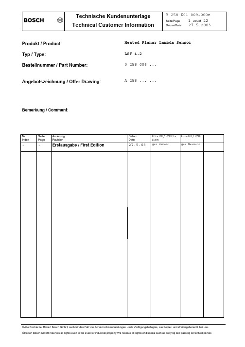
Produkt / Product:Heated Planar Lambda Sensor Typ / Type:LSF 4.2Bestellnummer / Part Number:0 258 006 ... Angebotszeichnung / Offer Drawing: A 258 ... ...Bemerkung / Comment:Nr. Index SeitePageÄnderungRevisionDatumDateGS-EX/ENG2-HamGS-EX/ENG--Erstausgabe / First Edition27.5.03gez Hamann gez NeumannContents1.Characteristics32.Application conditions53.Functional values84.Environmental test specification125.Carrying out tests166.Evaluation of field parts177.Design variations188.Installation instructions19Reference SpecificationsApplication guideline KGS_LSHandling instruction Y 258 E00 000Temperature measurement sensors Y 258 E00 006Test method: measurement temperature and Y 258 E00 007thermoshockMeasurement in propane gas Y 258 P02 042Measurement in synthetic gas Y 258 E00 004For design variations different values are marked.For explanation of variations see section 7.GeneralThe lambda sensor LSF4 is a planar 2-state λ=1 sensor of ZrO2 (Nernst-principle) with an integrated heater.It can be used for 2-state closed loop control of λ=1 automotive engines as well as catalyst monitoring sensor in OBD systems.Note: values signed with [N] in this document are nominal values or guide values. They depend directly on other values which are specified with tol-erances elsewhere in this paper.1.Characteristics1.1Electrical connection-sensor signal:2-pole, isolated ground-sensor heater:2-pole1.2Isolation resistance:(all measurements in static air, heater off)-between housing and each heater- and sensorcircuit connector pin for new sensors atroom temperature, measured with 800V DC:≥ 30 MΩ-between heater and sensor circuit for newsensors at room temp., meas. with 800V DC:≥ 30 MΩ-between heater and sensor circuit at 570°Chexagon temperature, new and after agingacc. to section 4.1, measured with 12V DC:≥ 500 kΩ-between sensor circuit and housing at 570°Chexagon temperature, new and after agingacc. to section 4.1, measured with 12V DC:≥ 10 kΩ1.3Heater performanceNominal heater power with 13 V heater voltagein propane gas burner Y 258 P02 042 at 350°C:7 Watt[N]Short term max. heater current with13 Volt at -40°C ambient temperature: ≤ 2.1 A[N]Nominal heater cold resistance atroom temperature for new sensor,including cable and connector:9.0 Ω[N]1.4 Heater supply Nominal voltage:12 VMaximum permissible effective heater voltage V H,eff,max - continuous:12 ... 14 V - max. 1 % of total life time ≤ 15 V(exhaust gas temperature ≤ 850°C)- short-term for max. 75 s.≤ 18 V(exhaust gas temperature ≤ 350°C)Maximum system supply voltage V Batt,max ≤ 16.5 V (with duty cycle of heater to V H,eff,max )- short time voltage peak for 60ms≤ 28 V(10 times over lifetime,ceramic temperature ≥ -40°C)Test voltage:13±0.1 V(for tests in section 3 an 4)Minimum frequency of heater duty cycle control:≥ 2 HzNote: the use of the sensor with 24V power systems is not permissible except if a voltage converter systems is used.During the condensation water phase the heater power must be limited (by heater power duty cycling), to rule out thermo shock damage of the sensor ceramic, see measuring method Y 258 E00 007.Heater voltage during condensation water phase V H,eff ≤ 4 V← application specific → time after start2.Application conditions2.1Temperature measurementsTemperature measurements are performed with a special sensor equipped with NiCrNi thermocouples, see sketch. Sensor Type "MABCD" has measurementpoints at the upper side of the PTFE formed hose (T upperhose), the cable grom-met (T grommet), the hexagon of the sensor housing (T hexagon) and for the exhaust gas temperature (T exhaustgas).For more information see description of temperature measurement sensorsY 258 E00 006 and measurement method Y 258 E00 007.T Exhaustgas T Grommet T Upperhose2.2Storage temperature (passive):-40°C ... +100°CStorage conditions see handling instruction Y 258 E00 0002.3Operating temperaturesExhaust gas (T Exhaustgas):≤ 930°CMinimum exhaust gas temperatureis to be tested application specific.Recommendation:≥ 150°CHexagon of the sensor housing (T Hexagon):≤ 570°CCable grommet (PTFE formed hose)- sensor side (T Grommet):≤ 250°C- cable side (upperhose crimp, T Upperhose):≤ 200°CCable and protective sleeve:≤ 250°CConnector:≤ 120°Cresp. according toconnector supplier spec.2.4Maximum temperatures2.4.1max. 250 h accumulated over lifetimeExhaust gas (T Exhaustgas):≤ 1030°CHexagon of the sensor housing (T Hexagon):≤ 650°C2.4.2max. 40 h accumulated over lifetime in intervals of max. 10 minutesCable grommet (PTFE formed hose)- sensor side (T Grommet):≤ 280°C- cable side (upperhose crimp, T Upperhose):≤ 230°CCable and protective sleeve:≤ 280°CNotes:If the gas temperature of 930°C is exceeded, the heater power must beswitched off.If the max. gas temperature exceeds 930°C or hexagon temperature exceeds570°C, the use of a longer thread boss is recommended (see section 8.9).If the operating temperature is exceeded (within the max. temperaturelimits) for more then 10 minutes without break, the sensor function might be affected during this time.2.5When condensation water is present at exhaust side, the heater power of thesensor must be limited, see 1.4.2.6Permissible vibrations(measured at the sensor housing)Stochastic vibrations:≤ 1000 m/s2(peak level)Sinusoidal vibrations-vibration displacement:≤ 0.3 mm-vibration acceleration:≤ 300 m/s22.7Continuous DC, sensor circuit≤| 10 µA |exhaust gas temperature ≥ 350°CContinuous AC (f ≥ 1 Hz)≤ 10 µAexhaust gas temperature ≥ 350°C2.8Maximum sensor internal resistance that can beused for indication of ready-to-control mode:10 kΩ2.9Permissible fuel additivesIn accordance with DIN EN228 for commerciallyavailable unleaded fuel.For use of leaded fuel see section 6.22.10Oil consumption and oil brandPermissible figures and data must be determined by thecustomer by the way of adequate large-scale tests.Guide value: ≤ 0.7 l/1000 km2.11LifetimeThe technical development of the sensor is aligned to a service life of160.000 km and a maximum life time of 10 years.A sensor with the protection tube variation “d4” (see sec. 7.1) is designedfor a service life of 250.000 km and a maximum life time of 15 years.Failure criterion is the non-compliance with the functional values asmentioned in section 6.The following conditions must be fulfilled in order to reach this service life:-Application conditions acc. to section 2.-Installation conditions acc. to section 8.-Checking of each application/installation location according to applica-tion guideline KGS_LS-Usage of a RB approved sensor connector with single chamber sealing and gold plated sensor signal contacts.The commercial warranty and liability is regulated in the conditions ofdelivery, independent of the above figures. The aforesaid information onlifetime for which the product has been construed shall in no case be aguarantee regarding the condition or quality of the product.3.Functional valuesSpecial hints for carrying out test bench measurements:Due to low gas speed and lack of gas pulsation in the propane gas burner,the sensors have a reduced gas exchange at the active sensor ceramic ele-ment. This leads to a different behavior of the dynamic sensor characteris-tics compared to real vehicle exhaust gas conditions. Especially the re-sponse times in the propane gas burner are badly reproducible and therefore only to be understood as guide values.Due to the technical design of the gas test benches (PSG and propane gas burner) these measurement data cannot be used for capability calculations.The 850°C measurement in propane gas burner is only permissible if this exhaust temperature in the field has been reached or exceeded for an ex-tended period of time.New sensors and sensors from defined endurance-run programs are measuredwith an applied test voltage as in sec. 1.4, if not otherwise specified.3.1Sensors with protection tube …d1“Measurement with synthetic gas test bench Y 258 E00 004 at 350°C New After 500 h After 2000h StaticCharacteristic λ statat 450 mV output 1.005±0.004 1.006±0.005 1.009±0.007Closed Loop Testλ dyn1.009±0.004 1.010±0.005 1.012±0.006frequency (Hz)2.9 ± 0.72.9 ± 0.72.5 ± 1.0Measured with synthetic gastest bench Y 258 E00 004 at 20°CLight-off time (s)Time to reach a sensor output of 600mV with rich gas of λ=0.97≤ 12 ≤ 12 ≤ 123.2Sensors with protection tube …d2“ (see sec. 8)Measurement with synthetic gas testbench Y 258 E00 004 at 350°C New After 500 h After 2000hStatic Characteristic λ statat 450 mV output1.002±0.006 1.003±0.007 1.007±0.007Closed Loop Testλ dyn 1.008±0.004 1.009±0.005 1.011±0.006 frequency (Hz) 2.3 ± 1.0 2.3 ± 1.0 2.3 ± 1.0 Measured with synthetic gastest bench Y 258 E00 004 at 20°CLight-off time (s)Time to reach a sensor outputof 600mV with rich gas of λ=0.97≤ 12≤ 12≤ 123.3Sensors with protection tube …d4“ (see sec. 8)Measurement with synthetic gas testbench Y 258 E00 004 at 350°C New After 500 h After 3000hStatic Characteristic λ statat 450 mV output1.006±0.006 1.007±0.007 1.008±0.007Closed Loop Testλ dyn 1.010±0.004 1.010±0.005 1.010±0.006 frequency (Hz) 2.7 ± 1.0 2.7 ± 1.0 2.7 ± 1.0 Measured with synthetic gastest bench Y 258 E00 004 at 20°CLight-off time (s)Time to reach a sensor outputof 600mV with rich gas of λ=0.97≤ 12≤ 12≤ 123.4Measurement with special gas composition for sensors after operationdownstream catalystSensors which are used in an application downstream catalyst are measured with a special gas composition. This composition corresponds to a gas after an aged catalyst with 97% HC conversion rate. These characteristics arevalid for the specified test gas only. In an engine exhaust, the gas compo-sition might be different, depending on application.Characteristics for all protection tube variants, new and after endurance run downstream catalyst, acc. to sec. 4.1.2Measurement with synthetic gas testbench Y 258 E00 004 at 350°C with special gas composition Heater voltageU H = 10VHeater voltageU H = 13Vλ stat at 450 mV sensor output1,0000 ± 0,00101,0000 ± 0,0010λ stat at 600 mV sensor output0,9999 ± 0,00100,9998 ± 0,0010λ stat at 700 mV sensor output0,9996 ± 0,00100,9990 ± 0,00154.Environmental test specificationEach test must be carried out with new sensors. If not otherwise specified, after the tests the sensors must fulfil the functional values of aged(2000/3000h) sensors as in section 3. The sensor heater is operated with a test voltage as in sec. 1.4, if not otherwise specified.4.1Engine endurance runFor measurements of functional values after endurance test the sensors have to be fitted into the exhaust system of a λ=1 controlled gasoline engine.Speed and load are changed in a 6-cycle program so that a temperature curve is reached in the sensor tip as per sketch.-Fuel: according to DIN EN228 for commercially available unleaded fuel.-Oil consumption ≤ 0,04 l/h.-Oil brand: multi-range oil viscosity 10W-40, API specification SF.Compliance with the temperature limits as per section 2 must be ensured by adequate cooling. The sensor heater is switched on in the test (13±0.5V).After the test the functional values for aged sensors in section 3 must be fulfilled.The exhaust gas temperature is set by varying engine speed and load.The temperature at the hexagon is limited by additional air cooling.Test time: 500h and 2000h (sensors with protection tube ...d1“ and (2)500h and 3000h (sensors with protection tube …d4“)4.1.1The sensors are installed upstream catalyst.4.1.2The sensors are installed downstream catalyst.T1 = exhaust gasT2 = housing hexagon4.2Sinusoidal vibration test acc to IEC 68-2-6 test FcTest equipment: electrodynamic vibratorTest between 50...150 Hz at constant amplitude ± 0,3 mm and between150...500 Hz at constant acceleration of ± 300 m/s2.Frequency change velocity: 1 octave/min.Test duration:8 h to be performed in all 3perpendicularplanes.Sensor mounting: see sketchAmbient temperature:25 ± 3 °C.The heater has to be switched on during the test.4.3Random vibration testTest equipment: Random vibration test benchas per Bosch standard N42 AP 411.Acceleration: 1000 m/s2 (peak level)Test duration: 24 hSensor mounting: see sketchAmbient temperature: 25 ± 3°CThe heater has to be switched on during the test.Sensor mounting for 4.2 and 4.330320129020 1221683745°46281022A4.4Test with damp heat, cyclic (12+12-hour cycle)acc. to IEC 68-2-30, test DbNo. of cycles: 21max. air temperature: 40°CThe heater has to be switched off during this test.4.5Salt mist test acc. to IEC 68-2-11, test KaTesting time: 288 hThe sensor heating is switched on 5 minutes before and during testing. In order to prevent water from reaching the sensor ceramic a stainless steel sleeve is screwed onto the sensor thread for proper sealing.4.6Change of temperature acc. to IEC 68-2-14, test NaMinimum temperature: -40 °CMaximum temperature: 130 °CExposure duration at each temp.: 30 min.No. of temperature cycles: 250The heater has to be switched off during this test.4.7Sulfur dioxide test with general condensation of moistureacc. to DIN EN ISO 6988No. of cycles: 6 (24 h for each cycle)The heater has to be switched off during this test. In order to protect the sensor ceramic a stainless steel sleeve is screwed onto the sensor thread for proper sealing.4.8Submergence test acc. IEC 529, IPx7Water level 150 mm above sensor cable outlet. Test duration is 30 min. The connection system must be out of the water during the test.The sensor voltage is monitored during the test. ∆ U ≤ 10 mV.The sensor heating is switched on 5 minutes before and during testing. In order to prevent water entering the sensor ceramic a stainless steel sleeve is screwed onto the sensor thread for sealing.4.9Wire pull testThe mounted sensor has to withstand an axial force of 100 N applied to the wire harness for 1 min.4.10Fuel resistance test (FVP-test)The exhaust gas side of the sensor is exposed to Pentane vapor in a testchamber (pressure 5mbar). The soak time is 2 h. After this the sensor isremoved and the heater is switched on. The sensor signal in ambient air is monitored for 120 min. A failure is defined as a decrease of the sensorslean output voltage below -100 mV.4.11Fine leak testThe gas leakage is measured from exhaust gas side with an air pressure of4 bar. The leakage rate must be smaller than 0.1 ml/min.4.12Drop test acc. to IEC 68-2-32 test Ed proc. 1The sensor is dropped to a concrete floor from a height of 1m for one time.4.13Test to Silicon sensitivityEngine test run with additional silicon content in fuel.The sensors are fitted in the exhaust pipe of a λ=1 controlled engine as in5.1, but with the following conditions:exhaust gas temperature: 400°Ctest time: 6 hSi content in fuel: 0.12cm3/l Oktamethylcyclotetrasiloxane fuel consumption over the test time: 18 lTest evaluation: static lambda in synthetic gas (see section 4) must bewithin the range of 1.000 ... 1.0165.Carrying out testsNote:Product audit tests are carried out for monitoring the product quality on a regular basis.DV tests are only carried out with new sensor types in the design verifica-tion phase.6.Evaluation of field partsIn case of complaints about the products they are effectively free of fault through attainment of the following characteristic data:6.1Sensors from operation with unleaded fuelMeasurement in propane gas burner test bench Y 258 P02 042 at 350°CSensors with protection tube d1d2d4800±60800±60815±60 Sensor voltage (mV)at λ=0.97 (CO=1%)50±4050±4050±40 Sensor voltage (mV)at λ=1.10Internal resistance (kΩ)≤1.0≤1.0≤1.0<125<400<400 Response time (ms)600 mV ... 300 mV< 60<400<200 Response time (ms)300 mV ... 600 mVHeater current (A)0.48±0.100.48±0.100.48±0.10If these figures are fulfilled, the sensor will be capable of closed loop control under normal operation conditions. However since a vehicle's ex-haust gas emission values also depend to a great extent upon other compo-nents in the system (engine, catalytic converter, mounting position,closed-loop control circuit), these figures cannot be taken as a reliable indication of emissions behavior in an emission test.6.2Sensors from operation with leaded fuelMeasurement in propane gas burner test bench Y 258 P02 042 at 350°CSensor voltage (mV)≥ 625at λ=0.97 (CO=1%)Sensor voltage (mV)-100 (80)at λ=1.10Internal resistance (kΩ)≤ 1Response time (ms)≤ 800600 mV ... 300 mVResponse time (ms)≤ 800300 mV ... 600 mVHeater current (A)≥ 0.30Depending on the lead contents of the used fuel the expected service life time is:-for 0.6 g Pb/l: 20 000 km-for 0.4 g Pb/l: 30 000 km-for 0.15 g Pb/l: 60 000 kmIn general, when using leaded fuel the sensor will be replaced, whenfunctional problems occur, e.g. unstable idle speed, driveability problems.The system diagnose functions should be rechecked for the reduced demands on the sensor and the increased response times when leaded fuel is used.7.Design variationsThe following variations are available:7.1Protection tubes•Sensor with protection tube type “d1” with big holes.•Sensor with protection tube type “d2” with smaller holes.•Sensor with protection tube type “d4” with smaller holes.Sensors with d2 and d4 tube can be applied in cases of high particulateconcentration in the exhaust gas. The d2 protection tube gives also a par-tial improvement regarding the resistance against condensation water in the exhaust gas at engine start (thermoshock).7.2PTFE formed hose•Longer PTFE hose at cable grommet for installation with critical•temperature conditions in the sensor area.•Shortened PTFE hose at cable grommet.Note: the temperature resistance is the same for both types at the defined measuring points.8.Installation instructionsThe sensor installation point and the sensor functionality in the fullsystem must be assured sufficiently by the customer through appropriate ve-hicle tests under realistic conditions of use.8.1Installation in the exhaust system must be at a point guaranteeing repre-sentative exhaust gas composition whilst also satisfying the specified tem-perature limits.8.2The heater power must always be switched on and operated respecting thedata in section 1.4, if necessary by heater voltage duty cycling. Atbooster starts the heater must be switched off.8.2.1To avoid signal injection of the heater voltage in the λ-sensor signalcircuit while the sensor is cold (high sensor resistance), the sensor sig-nal must not be evaluated for control or diagnose in the first 4 secondsafter full heater start.8.3The sensor ceramic element is heated up quickly after heater start.After heating up the ceramic all occurrence of condensation water, whichcould damage the hot ceramic, must be ruled out.To allow early heating of the sensor to reach a fast sensor activity, the sensor installation location design must be selected in a way to minimize exhaust-side stressing of the sensor with condensation water.If this is not possible by design measures, the start of the sensor heater must be delayed until demonstrably no more condensation water appears.8.3.1Design measures:-Locate sensor as close to the engine as possible, respecting max. al-lowed temperature range-The exhaust pipe in front of the sensor must not contain any pockets, projections, protrusions, edges flex-tubes etc. to avoid accumulation ofcondensation water. A downwards slope of the pipe is recommended.-Make sure, that the front hole of the double protection tube does not point against exhaust gas stream.-Attempt to achieve rapid heating-up of the exhaust pipes in the area in front of the sensor and also of the complete sensor thread boss area, toavoid developing of condensation water-The sensor thread boss must be designed as shown in 8.9 to reach a rapid heat up of the sensor protection tube area. Make sure, that the protec-tion tube is fully reaching into the exhaust gas stream.8.3.2System measures:-Never switch on sensor heater before engine start.-Delay of sensor heater start or power control of the sensor heater, e.g.as a function of engine and ambient temperature (see sec. 1.4) Test method for evaluation see Y 258 E00 007.8.4Installation angle must be inclined at least 10° towards horizontal (elec-trical connection upwards). Thus preventing the collection of liquids be-tween sensor housing and sensor element during the cold start phase.Other installation angles must be inspected and tested individually.8.5Avoid excessive heating up of the sensor cable grommet, particularly whenthe engine has been switched off after running under max. load conditions.8.6The use of cleaning/greasing fluids or evaporating solids at the sensorplug connection is not permitted.8.7Assembly with special high temperature resistant grease on the screw-inthread (e.g. Bosch-No. 5 964 080 112 for the 120g tin).8.8Tightening torque: 40-60 Nm, material characteristics and strength of thethread must be appropriate.8.9Recommended material for thethread boss in the exhaust pipe:Temperature resistant stainlesssteel, e.g.X 5 CrNi 18 10, DIN 17440 1.4301or 1.4303 or SAE 30304 or SAE30305 (US standard)Thread boss dimensions should beas in sketch, note that sensorthread must be covered com-pletely.Recommendation(*): For hot appli-cations (T Hexagon>570°C orT gas>930°C) the thread boss shouldbe min. 13mm to avoid overheatingof the protection tube weldingand to cool down the sensor hexa-gon.If the length is ≥16mm (max. 22mm permissible) the danger of thermo shock will be increased due to condensation water formation inside the protection tube. This must be covered separately by measurements described in Y 258E00 007.8.10Electrical connectors: A waterproof version is required.8.11The sensor and connection must be covered when underbody sealant (wax, taretc.) or spray oil is applied to the vehicle.8.12The influence of contamination which enters the exhaust gas through theintake air or as a result of fuel, oil, sealing materials etc., and thusreaches the λ-sensor is application specific and must be determined by cus-tomer tests.8.13The sensor must not be exposed to strong mechanical shocks (e.g. while thesensor is installed). Otherwise the sensor element may crack without visi-ble damage to the sensor housing.8.14For physical reasons the sensor needs ambient air at its reference gasside. Replacement of the air volume inside the sensor must be guaranteed bya sufficient air permeability of the wires and the connectors between sen-sor and ECU. The breathability should be higher than 1 ml/minute at a test pressure of 100mbar.8.15Underfloor installation of the sensor at a distance from the engine re-quires an additional check of the following points:-positioning of the sensor with respect to stone impact hazard-positioning and fixing of cable and connector with respect to mechanical damage, cable bending stress and thermal stress.8.16The PTFE formed hose is part of the reference air volume of the sensor andmust be kept sealed and undamaged. For installation, the minimum bendingradius of the hose must be 20mm (for long PTFE hose) resp. 12mm (for short hose). Keep the PTFE formed hose away from sharp edges and avoid con-tact/friction with frame/engine assembly.The first fixing point for the cable to the car body should be 200mm to400mm after the end of the PTFE formed hose, depending on movement of the exhaust system.8.17The sensor must not be exposed to continuous, one-sided dripping of water,e.g. by the air conditioning condensation water outlet. The thermal stresscould lead to mechanical damage of the sensor.8.18Additional instructions for the installation downstream of the catalyticconverter (data for OBDII applications)-Between catalyst and sensor location absolute gas tightness of the exhaust system must be ensured.-When the sensor is installed in the exhaust pipe there should be no discon-nectable connections between catalytic converter and sensor (e.g. flange, clamp-screw joint).-In order to protect the active sensor ceramic the sensor heater voltage must be power controlled after engine start during the condensation water phase, see 1.4.8.19Note for application of sensors downstream the catalytic converter:the sensor output on the rich side (≥600mV) is temperature dependent. For the outer loop control with the rear sensor the ceramic temperature of the sensor element should be kept to a constant temperature (control of heater power depending on engine operation conditions).Recommended guide value for application: 600°C ... 700°C ceramic tempera-ture, corresponding to a sensor internal resistance R I,N of 300Ω...120Ω(measured with 1...4kHz) for new sensors. The temperature data are guidevalues[N], the temperature of the assembled sensor can not be measured.Temperature dependency of sensor output downstream catalyst [N] (schematic)450,00500,00550,00600,00650,00700,00750,00800,00T Keramik / °CTemperature dependency of internal resistance, average and scatter band(guide value [N])。

dioxus 原理
Dioxus是一种基于IO-Link技术的氧传感器,其原理基于电化学传感技术。
以下是Dioxus传感器的工作原理:
1. 氧传感器:Dioxus传感器内部包含一个氧气敏感电极和一个参比电极。
这两个电极之间的电位差与被测试气体中的氧气浓度成正比,通过测量电位差可以确定氧气浓度。
2. 内部电路:Dioxus传感器内部有一个集成的电路,用于处理从电极接收到的电位差信号。
该电路可以通过IO-Link接口与外部设备进行通信。
通过IO-Link接口,可以实现传感器的远程控制和数据传输功能。
3. IO-Link技术:IO-Link是一种数字通信协议,可以将传感器与其他设备进行连接,如PLC(可编程逻辑控制器)或SCADA(监控和数据采集系统)。
通过IO-Link,Dioxus传感器可以实现与其他设备的实时通信,向用户提供可靠的氧气浓度数据。
4. 环境适应性:Dioxus传感器具有良好的环境适应性。
它可以在不同的工业环境中工作,并具有高度的抗干扰能力。
传感器可以自动进行自我校准,以消除温度、湿度和气压等因素对测量结果的影响。
总结:Dioxus传感器是一种基于IO-Link技术的氧传感器。
它利用电化学传感技术来测量被测试气体中的氧气浓度,并通过IO-Link接口与其他设备进行通信。
该传感器具有良好的环境
适应性和抗干扰能力,可以在工业环境中实时提供可靠的氧气浓度数据。

光纤传感器品牌和参数指标
光纤传感器是一种利用光纤作为传感元件的传感器,常用于测量温度、压力、应变等物理量。
目前市面上有许多知名的光纤传感器品牌,例如Honeywell、OMRON、Keyence、FiberSensys、FISO Technologies等。
这些品牌都提供各种不同类型和规格的光纤传感器,以满足不同应用场景的需求。
光纤传感器的参数指标通常包括以下几个方面:
1. 灵敏度,光纤传感器的灵敏度是指其对被测量的物理量变化的响应能力,一般以单位变化引起的传感器输出信号变化来表示。
2. 分辨率,光纤传感器的分辨率是指其能够分辨出的最小物理量变化,分辨率越高,测量精度越高。
3. 测量范围,光纤传感器的测量范围是指其能够有效测量的物理量的范围,不同型号的光纤传感器具有不同的测量范围。
4. 响应时间,光纤传感器的响应时间是指其从接收到输入信号到产生输出信号的时间,响应时间越短,传感器的实时性越好。
5. 工作温度范围,光纤传感器的工作温度范围是指其能够正常
工作的温度范围,一般来说,工作温度范围越宽,适用性越强。
除了以上参数指标外,光纤传感器还可能具有其他特殊的参数
指标,如防护等级、耐久性等,这些参数指标会根据具体的应用需
求而有所不同。
选择合适的光纤传感器时,需要根据实际应用场景
的要求来综合考虑这些参数指标,以确保传感器能够满足实际需求。


产品手册ASF01微流量传感器产品手册AFS01更多详情请登陆:产品手册AFS01文档修改记录日期版本修改内容2018-03-16V1.0初版2019-08-10V1.1添加产品量程规格表2021-03-11V1.2修改产品引脚顺序产品手册ASF01特性5V工作电压工作温度范围-25℃~85℃出厂经过完全标定校准I2C数字接口通信低功耗:小于50mW可用于非腐蚀气体超长使用寿命高使用频次滞后误差小安装接口简便产品概述AFS01是一款超高响应速度,长期输出稳定,高精度,完全校准的气体微流量传感器。
现代化的制作工艺,确保产品具有极高的可靠性与卓越的长期稳定性。
微流量传感器是利用本公司研发生产的传感器芯片,应用热传递原理测量气体流量综合集成数字处理的一款产品。
内部由一个热式传感芯片检测传感器和一个高性能集成24位AD采集的CMOS微处理器相连接。
该产品具有品质卓越、超快响应、抗干扰能力强、性价比高等优点。
整机集成度高,非常适合于高质量、大规模生产的要求,是用户理想的选择,便于合作厂商的OEM应用。
AFS01通信方式采用I2C数字通信方式,超小的体积、极低的功耗,使其成为各类应用领域精工气体应用场合的最佳选择。
AFS01工作电压为5V,该模块产品可为各类常见应用场景提供低成本和低功耗优势,微流量传感器均在高精度的气体标准生产实验室中进行出厂校准,直接输出检测到的流量输出量,用户不需要再进行信号二次处理,便可得到准确的流量信息,降低用户使用成本,方便用户产品方案应用,减少繁琐的二次开发。
应用范围流量传感控制、医学理疗应用仪器气体流量监测、特效科技烟、香氛香料气体配比控制、工业化包装充气及食品防腐、电子SMT生产及半导体化学电子设备、智能自动化开关和机械领域、工业开发实验室应用等。
OEM行业定制与解决方案我司致力于研发各类传感器,有专业的研发实验室及仪器设备,配套多种仿真环境实验条件,打造高品质产品生产与检验工艺。
2024年分布式光纤传感器市场规模分析1. 简介分布式光纤传感器是一种利用光纤作为传感器的感测元件以及信号传输媒介的一种技术。
随着物联网、工业自动化等领域的快速发展,分布式光纤传感器的应用越来越广泛。
本文将对分布式光纤传感器市场规模进行分析。
2. 分布式光纤传感器市场发展概况近年来,随着人们对安全性、可持续性和效率的要求不断提高,分布式光纤传感器市场持续增长。
分布式光纤传感器的应用范围涵盖石油、天然气、地铁、航空航天、电力、交通等多个领域。
其优势包括高灵敏度、长监测距离以及对多种物理参数的同步监测等。
3. 2024年分布式光纤传感器市场规模分析3.1 市场规模趋势根据市场调研数据,分布式光纤传感器市场规模呈现逐年增长的态势。
以2020年为基准,市场规模预计在2025年前将以年均增长率6%左右增长。
这一增长趋势主要受到以下因素的影响:•工业自动化的快速发展,推动了对分布式光纤传感器的需求增加;•物联网和智能城市的发展,对分布式光纤传感器的应用提出了更高要求;•传感器技术的不断创新,提高了分布式光纤传感器的性能和可靠性。
3.2 市场主要应用领域分布式光纤传感器的应用涵盖了多个领域:3.2.1 石油和天然气行业在石油和天然气行业,分布式光纤传感器广泛应用于油井、管道和油气储存设施的监测。
通过对温度、压力等参数进行实时监测,可以提高设备运行安全性,减少事故发生的可能性。
3.2.2 地铁和隧道监测分布式光纤传感器在地铁和隧道监测中扮演重要角色。
通过对隧道结构的监测,可以及时发现裂缝、变形等问题,确保运营安全。
3.2.3 电力系统监测分布式光纤传感器在电力系统监测中具有重要应用。
通过对电力输电线路的监测,可以实时发现线路的故障,提高电网的可靠性。
3.2.4 交通监测分布式光纤传感器在交通监测中发挥着重要作用。
通过对道路的监测,可以及时发现交通流量、车速等信息,为交通管理部门提供科学依据。
3.3 市场地区分布分布式光纤传感器市场在全球范围内分布广泛。
光纤传感器核心:法布里-珀罗的原理介绍[导读]FISO技术公司的专利白光交叉相关器提供了一个独特而强大的方法,使绝对法布里-珀罗腔长度测量具有惊人的精度和线性,提供持久的一致性。
FISO技术公司的专利白光交叉相关器提供了一个独特而强大的方法,使绝对法布里-珀罗腔长度测量具有惊人的精度和线性,提供持久的一致性。
这种传感背后的原理技术其实很简单,虽然有一些技术细节为了制造这样的装置,必须考虑。
首先是光源,即明亮的非相干光源注入并引导到多模光纤中,然后注入到耦合器的输入,作为一个50/50功率分配器。
一个输出是否通过位于信号调节器前面板。
然后,光穿过导线光纤,直到它到达传感器的顶端。
传感器的核心是法布里-珀罗干涉仪技术,这在光学科学界是众所周知的,一个多世纪以来,已被应用于许多研究领域比如物理学和天体物理学。
它由两条平行的线组成,完全平坦的半反射镜,由一个给定的间隙隔开。
光通过第一面镜子时,会前后反射两个平行镜之间的大量时间。
然而,每次反射时,入射光束的一小部分会逃逸干涉仪产生大量平行光束与他们进入干涉仪的角度相同。
在自由空间中,通过a会聚透镜产生了多重的建设性干涉产生非常明亮和尖锐干涉条纹的光束。
它们的间距将取决于光程(即与平行平面与折射率之间的距离在这些平面之间)和自然波长上。
因此如果要由传感器测量的物理参数改变法布里-珀罗干涉仪的光程差(OPD)逃离干涉仪的光将根据这个编码变异。
使用白光干涉测量法的F-P绝对测量信号调节器的示意图如下:在光纤版本中,法布里珀罗干涉仪发出的光不是直接聚焦在一个平面上的,上面提到的干涉,但是光束是相当的重新注入到原来的光纤中然后它们返回,进入光学信号调节器连接器的水平。
然后,光又被耦合器分开两种纤维。
然而,指向光源的光却丢失了,另一种光纤将光导向一个光学盒,在那里光被照亮是散布在一个重建干扰的菲索楔上,使用电荷耦合装置进行物理记录的图形(CCD)。
由于使用的是白光,所以所有波长都是除零点外,均存在破坏性干扰所有波长都是建设性的。
Pressure sensors SPAE2d Internet: /catalogue/...Subject to change – 2023/08Pressure sensors SPAEKey featuresAt a glance• Single-button operation • 7-segment display• Switching status indication• Various pneumatic connection options• Choice of pressure rangesFunctionThe SPAE is an electronic pressure sensor with piezoresistive pressure measuring cell, integrated signal processing, pressure indicator with percentage, control button and a switching output, PNP/NPN switchable. Two switching signals and the measured value can be transmitted via IO-Link.• The sensor can be set using the key and display oralternatively using IO-Link or teach-in• Switching functions: threshold value or window comparator• Switching logic: normally open (NO) or normally closed (NC)• Threshold values and hysteresis are adjustable• Display of minimum and maximum measured values• Display can be rotated and switched off• Protection against tampering using security code• All parameters that have been input can be transferred to other SPAE(replicator function)H- -NoteThe version with 10 mm cartridge is designed for the vacuum generator OVEL.Pressure sensors SPAE Peripherals overview3 2023/08 – Subject to change d Internet: /catalogue/...4d Internet: /catalogue/...Subject to change – 2023/08Pressure sensors SPAEType codesH- -NotePressure measuring range: Additional pressureranges on request (batch size 40)52023/08 – Subject to changed Internet: /catalogue/...Pressure sensors SPAEData sheetFunction-P- Voltage 18 ... 30 V DC-L- Pressure measuring range –1 ... +10 bar -Q-Temperature range0 ... +50°C1)Corrosion resistance class CRC 2 to Festo standard FN 940070Moderate corrosion stress. Indoor applications in which condensation can occur. External visible parts with primarily decorative surface requirements which are in direct contact with a normal industrial environment.2)For information about the area of use, see the EC declaration of conformity at: /catalogue/... d Support/Downloads.If the devices are subject to usage restrictions in residential, commercial or light-industrial environments, further measures for the reduction of the emitted interference may be necessary.Pressure sensors SPAEData sheet6d Internet: /catalogue/...Subject to change – 2023/08Pressure sensors SPAE Data sheet7 2023/08 – Subject to change d Internet: /catalogue/...Pressure sensors SPAEData sheet8d Internet: /catalogue/...Subject to change – 2023/08Pressure sensors SPAE Data sheet1)Additional pressure ranges on request (batch size 40)9 2023/08 – Subject to change d Internet: /catalogue/...Pressure sensors SPAE Accessories Mounting clip SAMH-PE-MC-1Material:POMNote on materials:RoHS-compliantMounting clip SAMH-PE-MC-8Material:POMNote on materials:RoHS-compliantH--NoteThe mounting clip SAMH-PE-MC-8 can be shortened by the user to the requirednumber of slots.10d Internet: /catalogue/...Subject to change – 2023/08Festo - Your Partner in AutomationConnect with us/socialmedia 1Festo Inc.2Festo Pneumatic 3Festo Corporation 4Regional Service Center 5300 Explorer DriveMississauga, ON L4W 5G4CanadaAv. Ceylán 3,Col. Tequesquináhuac 54020 Tlalnepantla, Estado de México1377 Motor Parkway Suite 310Islandia, NY 117497777 Columbia Road Mason, OH 45040Festo Customer Interaction CenterTel:187****3786Fax:187****3786Email:*****************************Multinational Contact Center 01 800 337 8669***********************Festo Customer Interaction Center180****3786180****3786*****************************S u b j e c t t o c h a n g e。
四方光电电力系统监测技术说明书目录一、光纤光栅传感技术简介 . .................................................................................................................. - 2 -二、光纤光栅开关柜及母线接头温度在线监测系统方案设计 ........................................................... - 5 -3.1概述 . ......................................................................................................................................... ... - 5 -3.2 光纤光栅开关柜及电缆接头温度监测系统介绍 . ................................................................... - 7 -三、 DTS 分布式光纤监测系统介绍及应用 ........................................................................................ - 15 -4.1 DTS分布式监测系统简介 ...................................................................................................... - 15 -4.2 DTS分布式光纤监测系统原理及特点 .................................................................................. - 15 -4.3 DTS分布式光纤温度监测系统介绍 ...................................................................................... - 17 -四、工程业绩 . ............................................................................................................ 错误!未定义书签。