MACKIE HR824示范级有源监听音箱说明书
- 格式:pdf
- 大小:552.32 KB
- 文档页数:8
用户手册DMC-842数字传声器接口带有线路(Line)输出的8通道数字传声器接口8通道AES转模拟/ADAT接口AES/EBU格式和采样率转换可选的64通道MADI接口24 Bit / 192 kHz数字音频MIDI远程控制重要的安全说明 (4)概述 (5)1. 简介 (6)2. 包装清单 (6)3. 简介及主要特点 (6)4. 首次使用——快速上手 (7)4.1 控制、接口与显示 (7)4.2 快速上手 (9)5. 附件 (9)6. 产品保证 (10)7. 附录 (10)CE / FCC符合性声明 (11)使用和操作 (12)8. 前面板控制 (13)8.1 Select(选择)键和旋钮(SET) (13)8.2 Clock Section(时钟部分) (14)8.3 模拟输出 (14)8.4 Remote(遥控) (15)9. 输入通道 (15)9.1 通用 (15)9.2 Gain(增益) (15)9.3 数字幻象供电 (15)9.4 Mode 2 (16)9.5 Stereo / Inactive (16)9.6 M/S处理 (16)9.7 SRC(采样率转换器) (17)9.8 PAR (17)9.9 Sync (17)10. Setup(设置)菜单 (18)10.1 通用 (18)10.2 ID(Id,自动ID) (18)10.3 Bank(bA,库) (18)10.4 Auto ID(Au,自动ID) (19)10.5 Delay Compensation(dC,延迟补偿) (19)10.6 Follow Clock(FC,跟随时钟) (20)10.7 Word Clock Out(Co,字时钟输出) (20)10.8 Peak Hold(Ph,峰值保持) (20)10.9 Digital Output(do,数字输出) (20)10.10 Analog Output(Ao,模拟输出) (21)10.11 Gain(GA,增益) (21)10.12 Control Pulse(Cp,控制脉冲) (21)10.13 Sync Pulse(SP,同步脉冲) (21)10.14 Special(SPECIAL) (22)11. Parameter(参数)菜单 (22)11.1 通用 (22)11.2 Low Cut(Lo-Cut,低切) (23)11.3 Directivity Pattern(PAttErn,指向性图) (23)11.4 Pre-Attenuation(AttEnuAtIon,预先衰减) (23)11.5 Mute(mute,静音) (23)11.6 Peak Limiter(LImItEr,峰值限制器) (23)11.7 Command Type(ComtyPE,命令类型) (23)12. Remote Control(远程控制) (24)12.1 MIDI (24)12.2 MIDI over MADI(借助MADI的MIDI) (24)12.3 Remote Control Software(远程控制软件) (25)12.4 RS232 (26)输入和输出 (27)13. 数字输入 (28)13.1 XLR (28)13.2 D-Sub - AES/EBU Sync(同步) (28)14. 数字输出 (29)14.1 AES/EBU (29)14.2 ADAT光纤 (30)14.3 I64 MADI卡 (31)14.4不同的MADI系列可配置I64 MADI卡和ADI-642 (32)15. 模拟输出 (33)16. 字时钟 (34)16.1 字时钟输入和输出 (34)16.2 技术描述和使用 (35)16.3 布线和终止 (36)17. MIDI (36)技术参考资料 (37)18. 技术指标 (38)18.1 模拟 (38)18.2 数字输入 (38)18.3 数字输出 (40)18.4 数字 (40)18.5 MIDI (40)18.6 通用 (41)18.7 固件 (41)18.8 MADI用户比特位 (41)18.9 接口针脚 (41)19. 技术背景 (43)19.1 术语 (43)19.2 锁定(Lock)与SyncCheck(同步检查) (44)19.3 延时(Latency)与监听(Monitoring) (45)19.4 DS –双倍速 (46)19.5 QS –四倍速 (46)19.6 AES/EBU - SPDIF (47)19.7 MADI基础 (48)19.8 SteadyClock(稳定时钟) (49)20. 框图 (50)21. DMC-842的MIDI实现 (51)21.1 基本SysEx格式 (51)21.2 通知类型–命令 (51)21.3 表格 (53)重要的安全说明注意! 不要打开底盘,以防触电。

X24数字音箱控制用户手册用户手册祝贺您购买了无极的专业音响产品!您现在拥有了适合高品质工程应用以及严格的音质要求的最优化产品,在投入使用之前,请先阅读本操作说明,可有助于您让您的设备最大限度的发挥其优异的性能。
第一节:首先请阅读以下内容1.1、安装注意事项在安装任何一台无极数字音箱处理器之前,充分考虑电源电力的安全并使用熟悉的部件是非常有必要的。
如果完全采用机柜进行安装,使用者必须清楚整体安全措施,并注意通风散热,同时安装人员必须具备必要的施工知识和技能。
无极强烈推荐按照以下的要求配备安装系统:1、具有完备的安装设计图纸和安装部件清单。
2、在实施之前,安装设计必须得到电气工程师,注册建筑师或其他有专业资格的人士的许可。
3、安装人员必须具有合格的安装和检查能力。
危险警示:当设备安装时,工作人员必须了解安装技术,并检查供电线路!第二节:拆除包装每一台无极音响产品出场都采用具有高标准的包装箱和包装材料,可保证每个产品在运输过程中都可以得到完善的保护。
当拆除包装时,请小心操作,并检查是否有损伤情况。
2. 1、运输损伤首先必须通过视觉检查产品的外部包装有无任何损伤,当取出音箱后,如果发现有音箱外部的隐蔽损伤,应保留包装材料供运输者检查,并向运输方申报相应的索赔权利。
虽然无极可能以任何方式帮助我们的用户,但是,有关运输方面的事情仍需要向承运方申报你的权利。
2. 2、产品退回如果产品必须要退回无极,请联系无极设备供应商或客户服务部门。
请用原有的包装箱和包装材料包装音箱。
如果包装箱损坏或丢失,请联系无极客户服务部门,以成本价格购买新的包装箱。
无极不负担因为使用不合适的包装造成的产品损坏引起的损失。
第三节:操作3.1、功能键及连接面板控制功能1、LCD显示屏,用于显示菜单和参数信息;2、MENU-主菜单选择键;3、EXIT-用于菜单之间的切换、返回;4、ENTER-快速进入Xover Sub-Menu子菜单;5、PARAMETER-用于修改参数,菜单切换,含Enter功能;6、输入静音/编辑键,每个键都有一个相对应的LED指示灯;7、输出静音/编辑键,每个键都有一个相对应的LED指示灯;8、输入电平指示灯;9、输出电平指示灯;10、输入电平旋钮,范围:-∞~ +6dB11、USB接口,和电脑进行连接,可使用本公司提供的电脑编辑软件对X24进行设置(温馨提示:输入、输出静音/编辑键,当此键被按下且非长按时,为静音切换操作;当此键被按下且为长按时,为修改所选择通道参数操作)背板功能1、电源开关2、电源插座,电压适应范围:90 ~ 240V3、输出卡侬座OUT1-OUT6,平衡输出阻抗20K欧,不平衡输出阻抗10K欧4、输入并联卡侬座5、输入卡侬座,输入阻抗:600欧3.2、操作与编辑启动电源当你起动电源开关之后,在 LCD 显示屏之上便可以看到以下的开机数据显示。
KRAMER ELECTRONICS LTD. USER MANUALMODEL:Dolev 82-Way, Bi-Amplified Studio-Grade SpeakerP/N: 2900-300418 Rev 1Contents1Introduction 1 2Getting Started 2 2.1Achieving the Best Performance 2 2.2Recycling Kramer Products 3 3Overview 4 4Defining the Dolev 8 5 5Installing the Speaker 6 5.1Choosing the Best Location 6 5.2Setting up Mid/Near-Field Installation 6 5.3Setting up Far-Field Installation 7 5.4Installing the Speaker 8 6Technical Specifications 9FiguresFigure 1: Dolev 8 Active 2-Way, Bi-Amplified Studio-Grade Speaker 5 Figure 2: setting the Dolev 8 at head height 6 Figure 3: Dolev 8 Optimum positioning 7 Dolev 8 –Contents1 IntroductionWelcome to Kramer Electronics! Since 1981, Kramer Electronics has beenproviding a world of unique, creative, and affordable solutions to the vast range ofproblems that confront video, audio, presentation, and broadcasting professionalson a daily basis. In recent years, we have redesigned and upgraded most of ourline, making the best even better!Our 1,000-plus different models now appear in 13 groups that are clearly defined byfunction: GROUP 1: Distribution Amplifiers; GROUP 2: Switchers and Routers;GROUP 3: Control Systems; GROUP 4: Format/Standards Converters; GROUP 5:Range Extenders and Repeaters; GROUP 6: Specialty AV Products; GROUP 7:Scan Converters and Scalers; GROUP 8: Cables and Connectors; GROUP 9:Room Connectivity; GROUP 10: Accessories and Rack Adapters; GROUP 11:Sierra Video Products; GROUP 12: Digital Signage; and GROUP 13: Audio.Congratulations on purchasing your Kramer Dolev8 2-Way, Bi-Amplified Studio-Grade Speaker, which is ideal for the following typical applications:∙Home theater ∙Sports bars∙Luxurious BoardroomsDolev 8 - Introduction 12 Getting StartedWe recommend that you:∙Unpack the equipment carefully and save the original box and packaging materials for possible future shipment∙Review the contents of this user manualGo to /support/product_downloads.aspto check for up-to-date user manuals, application programs, and to check iffirmware upgrades are available (where appropriate).2.1 Achieving the Best PerformanceTo achieve the best performance:∙Use only good quality connection cables (such as the KramerC-XLQM/XLQF) to avoid interference, deterioration in signal quality due topoor matching, and elevated noise levels (often associated with low qualitycables)∙Do not secure the cables in tight bundles or roll the slack into tight coils∙Avoid interference from neighboring electrical appliances that may adversely influence signal quality∙Position your Kramer Dolev 8 away from moisture, excessive sunlight and dustThis equipment is to be used only inside a building. It may only beconnected to other equipment that is installed inside a building.Do not open the housing of the speaker; doing so may reduce thequality of the sound.2 Dolev 8 - Getting Started2.2 Recycling Kramer ProductsThe Waste Electrical and Electronic Equipment (WEEE) Directive 2002/96/EC aimsto reduce the amount of WEEE sent for disposal to landfill or incineration byrequiring it to be collected and recycled. To comply with the WEEE Directive,Kramer Electronics has made arrangements with the European AdvancedRecycling Network (EARN) and will cover any costs of treatment, recycling andrecovery of waste Kramer Electronics branded equipment on arrival at the EARNfacility. For details of Kramer’s recycling arrangeme nts in your particular country goto our recycling pages at /support/recycling/. Dolev 8 - Getting Started 33 OverviewThe Dolev 8 is a high-quality, high-fidelity, studio grade speaker designed andcrafted for superior clarity and detail for high-end applications or any other task thatrequires precise, accurate and detailed sound, even at high volume levels.The Dolev 8 ensures that you hear exactly what is happening in the music andreveals all the original nuances of the sound, without adding to or subtracting fromthe signal. Premium components, an advanced cabinet design, and efficient bi-amplification come together to provide superior full-range sound—from crystal-clearhighs, to deep, rich bass tones. You can be confident that your music sounds itsbest in any listening environment.The Dolev 8 features:∙ A Two-way, bass-reflex, bi-amplified speaker∙ A 8” fiberglass woofer and a 1” neodymium dome tweeter∙ 1 unbalanced and 2 balanced audio inputs∙Four-position high-frequency gain control∙ A volume adjustment control knob∙Magnetic shielding4 Dolev 8 - Overview4 Defining the Dolev 8This section defines the powered Dolev 8:Figure 1: Dolev 8 Active 2-Way, Bi-Amplified Studio-Grade SpeakerDolev 8 - Defining the Dolev 8 55 Installing the SpeakerThis section explains how to:∙Choose the best location for your speakers (see Section 5.1)∙Setup mid/near-field (see Section 5.2) or far-field (see Section 5.3) Installation∙Install the speaker (see Section 5.4)5.1 Choosing the Best LocationFor optimum installation:∙Speakers should be positioned at least 50cm from the walls∙Install the Dolev 8 so that the center point between the tweeter and the woofer are at ear level. If required, use a speaker stand∙If required, use sound absorbing materials around the room∙Place the speaker facing towards the listener to minimize the distance and reflections from the walls and get the best stereo image5.2 Setting up Mid/Near-Field InstallationMid-field or near-field installation is usually directed towards a specific listener orlisteners in a specific location of the room. To maximize your listening experience:1. Make sure that the speakers are set at head height (whether you will be usingthe speakers sitting down or standing up).Figure 2: setting the Dolev 8 at head height6 Dolev 8 - Installing the Speaker2. Position the speaker at an angle so that together with the listener, anequilateral triangle is created.3. Try to keep the speakers at a distance of about 50cm from the walls4. Try to keep a distance of about 1.5 to 2 meters between the speakers.Figure 3: Dolev 8 Optimum positioningiNote that even though the illustration in Figure 3 shows twospeakers each Dolev 8 package includes one speaker.5.3 Setting up Far-Field InstallationFar-field positioning is suitable for a large amount of listeners (unlike the near-fieldpositioning where the speakers are directed at a specific listener). To maximize thelistening experience:1. Make sure that the speakers are facing the center of the room.2. Make sure that both speakers are placed along the same wall in the room(not facing each other).3. Aim to achieve the largest sweet spot.For optimum results we recommend that you either experiment and locate thesweet spot by trial-and-error or alternatively, consult an acoustic engineer.Dolev 8 - Installing the Speaker 75.4 Installing the SpeakerTo install the speaker, do the following:1. Connect one of the following inputs:▪An unbalanced input (for example, a computer sound card, portableplayer or DVD/CD player – C-A35M/2RAM) to the UNBALANCEDINPUT RCA connector▪ A balanced input (for example, a professional mixer or audio interfaces) to the BALANCED INPUT 6.35mm TRS connector▪ A balanced input (for example, a professional mixer or audio interfaces) to the BALANCED INPUT XLR connector2. Set the volume on the Dolev 8 to 12 o’clock (0dB)3. Connect the power.4. Set the volume on the input source to the minimum.5. Switch the Dolev 8 power on.6. On the input source, increase the volume control slowly until the desired levelis achieved.7. Adjust the high frequency response according to the room conditions:▪ A heavily dampened room requires raised high frequencies▪ A resonant room requires reduction of the high frequencies8 Dolev 8 - Installing the Speaker6 Technical SpecificationsDolev 8 - Technical Specifications 9For the latest information on our products and a list of Kramer distributors, visit our Web site where updates to this user manual may be found. We welcome your questions, comments, and feedback.Web site: E-mail: *****************P/N: 2900-300418 Rev: 1!SAFETY WARNING Disconnect the unit from the power supply before opening and servicing。

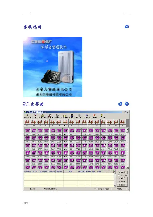
系统说明2.1主界面2.2系统登录软件默认登录用户名:admin密码:admin2.3分机更改进入参数设置菜单后,点击分机参数,再自编号栏找到原,双击即可输入新,输入新后按回车键,该栏显示绿色,表示设置成功,黄色表示设置失败。
如果更改所有的分机以3字开头,其他的按照顺序即可,可以在本分机参数上点击鼠标的右键,选择自编号的按输入顺序添加所有,然后输入3001,点确定即可。
2.4服务等级设置2.5分机来电显示设置2.6阻塞密码查看2.7闹钟设置2.8告警设置2.9提机方式设置2.10打出专线设置2.11打入指定振铃2.12分机分组设置2.13外线连接2.14电脑话务员使用2.15外线来电显示2.16计费方式2.17多局向2.18远程编程远程编程现在只能通过电子把要设置的功能通知编程人员,编程人员利用就近的交换机按要求编好,然后把程序备份,再通过电子方式把程序发来,利用数据备份中的导入功能将编好的数据恢复到当前的机器。
2.19实时监控分机摘挂机、振铃、通话、忙音状态,外线打出、打入、通话等状态,可以通过软件主接口实时显示。
实时状态图片显示的意义如下:2.20话费查询查询可根据指定的输入条件进行查询查询历史记录,也可打开月话单库来查询。
查询出结果后如果需要打印可按以下几种方式打印。
2.21话务管理有些酒店、宾馆对进行方便有效进行管理则可利用此功能,为了系统安全,管理员设置操作员级密码给需要对分机进行开关、设置闹钟、预设话费的工作人员进行有效的管理。
超额等级:等级的级别意义与服务等级一样,当你设置了预设话费时,余额为小于0,则分机的服务等级即为此等级,当你如果又增加预设话费,余额为大于0,此等级则无效,使用服务等级级别。
预设话费:双击目的分机预设话费栏,输入金额,回车底色变为绿色即生效。
例如:输入50元,输入50回车即可。
每输一次余额会自动累计,又如:输入-50元,回车后,余额会自动减计;如果想把余额清0,双击选定预设话费栏,把数字全部清除,再按回车即可。
Holtek HT82A824R高性能iHoltek公司的HT82A824R是高性能喇叭OTP ,集成了USB 2.0全速兼容SIE及符合微软WHQL要求之高性能数字模拟转换器与功率和微控制器.器件采纳Holtek(盛群)八位微控制器为其核心,可提供8Kx16之程序内存容量、864x8数据存储器以及512x8的只读数据存储器,并提供HALT 命令。
其操作为4.0V~5.5V,系统频率最高可达16MHz,同时可提供21条I/O,主要用在i-Phone/i-Pod/i-Pad Docking产品.本文介绍了HT82A824R主要特性,方框图和应用.HT82A824R高性能USB喇叭微控制器This HT82A824R is an 8-bit high performance RISC microcontroller designed for USB Speaker related product applications. The HT82A824R combines a 16-bit , USB transceiver, SIE (Serial Interface Engine), audio class processing unit, FIFO, 8-bit MCU into a single chip. The Sigma-Delta DAC in the HT82A824R is operating at the 48kHz or 44.1kHz sampling rate. The HT82A824R has a digital programmable gain amplifier. The gain range is from -32dB to +6dB. The external stereo audio input can be the other source of power amplifier by software control.The HT82A824R has a Human Interface Device function that allows a user to control the playback volume at the device side. The HT82A824R also can mute the analog output signal by the operation of HID buttons.HT82A824R主要特性:CPU Features●●USB 2.0 Full Speed Compatible●●USB spec V1.1 full speed operation and USB audio device class spec V1.0●●Operating voltage at fSYS = 6M/12MHz: 4.0V~5.5V第1页共3页。

噪音计AR824使用说明您所购买的这款“噪音计AR824”标志着您已步入到测量领域前沿。
该“噪音计AR824”是一款多元化、精美的产品,除去科技进步、升级,在正确操作下,该产品强度将足够您使用多年。
请仔细阅读使用说明,并将本手册放置于方便取阅处。
目录1. 属性----------------------------------------------------------------- 32. 详细说明------------------------------------------------------------- 3 3.前操作面板细节------------------------------------------------------- 6 4.测量步骤------------------------------------------------------------- 6 5.测量需要考虑的事(注意事项) ----------------------------------------- 7 6.信号输出------------------------------------------------------------- 8 7.电池更换------------------------------------------------------------- 8 8.调节器--------------------------------------------------------------- 8 9.A/C网络分析仪的频率测量特性------------------------------------------ 9 10.节拍测量(块&慢)特性 --------------------------------------------- 101. 属性大LCD显示器,便于阅读频率测量网络分析器满足IEC651-2款要求A&C测量网络分析器以适应标准节拍测量(块&慢)动力特性模式AC/DC输出扩展基于电子调节器电子减震系统前面板电容式麦克风,高准确度&长期稳定最大读值锁定功能以在显示屏上储存最大读值报警提示,负载超高或超低LCD显示,以减少能耗&清晰阅读—即使在周围强光环境中采用耐久材料,包括高强度轻质ABS所料外壳小巧而轻重设计,手持操作低电量报警2. 详细说明3.前操作面板细节3—1 电子电容式麦克风3—2 显示屏3—3电源开关&输出类型选项3—4 A/C测量&调节选项3—5 节拍测量(块/慢)/最大读值锁定选项 3—6 量程选项3—7信号输出终端3—8 电池间隔/支付(用完)3—9 量程超高/超低报警3—10 调整器电子减震系统(准确度调整减震器)4.测量步骤1)滑动“A/C测量选项”(3—4,Fig.1)到“A”或者“C”档来测量声音强度。
1use. It allows you to control your amp’s channel switching (1,2 or 3) via MIDI program change messages. The Anniversary amp has an internal memory and can store Channel 1,2 or 3 selection in 128 MIDI addressable patches. These correspond to the 0 - 127 MIDI PROGRAM CHANGE message.Rear Panel FeaturesThe rear panel of the Anniversary amplifier is the most comprehensive that we have ever produced. Inaddition to the connection and control facilities there are a number of major innovations that directly affect the sound and performance of the amplifier. As your sound is personal to you, it is important to try thedifferent options for the most suitable settings for your style.34. Footswitch Socket Accepts the connecting lead from the three way channelswitching footswitch (which is included with your unit).35. MIDI-In Socket For connection from an external MIDI device.36. Balanced Compensated XLR OutputBalanced output featuring Marshall line level SpeakerEmulation for accurate sound reproduction directly throughrecording equipment or PA (see operational note C).37. Compensated Output Level ControlProvides volume level control of the signal from item (36).Operational Note C: Speaker EmulationThe Marshall speaker emulation circuit provides a signal for direct connection to PA or recording mixers, that retains the true character of the amp driving a cabinet. The quality of this emulation is so high that ‘miking up’ cabinets should no longer be necessary, saving you both time and money, and guaranteeing you a great direct guitar tone.This output is active even when the power amp mute switch (item 39) is activated. Although this power amp mutingallows the amp to be used without speaker cabinets as with all valve amplifiers, it is wise to keep the cabinet connected.38. Uncompensated Line Output Line Out suitable for linking to further amplifiers to extendthe system.39. Uncompensated Link Selection SwitchWhen pushed in, this switch mutes the internal poweramp allowing operation as a pre-amp, switching in alsoactivates the line input to the power amp.40. Line Input Line level input jack to take an external pre-amp thususing just the power stage of your amplifier.Operational Note D: Series effects optionItems 38 & 40 can also be used as a 2nd series effects loop (See operational note F). The selection switch (Item 39) will switch the loop in or out of the circuit, but will not mute the power amp.41. Effects Send Trim Channel 1 Provides -10 to +4db level control of the effects sendfrom Channel 1 only.42. Effects Send Trim Channel 2Provides -10 to +4db level control of the effects sendfrom Channel 2.Operational Note E: Effects level balancingOn 41 & 42 - When setting up the effects loop, the effects processor’s level controls should be set up against the lead channel -3 and matched using switch (44), then channels 1 & 2 set up via the trim controls for an effects send balance.If desired, more or less sound level can be set for differing amounts of effected signal.543. Series/Parallel Selection Switch Selects series or parallel effects loop operation. Seriesconnection is most suitable for Graphic Equalizers,compressor limiters etc. Parallel connection suits delay,reverb and chorus effects. It is generally not advisableto link distortion effects through the loop. Operational Note F: Effects LoopThe main effects loop on this amplifier can be configured either as a series or a parallel loop by using theseries/parallel selection switch (item 43). The parallel loop (switch out) splits the pre-amp signal into two, retaining the direct signal within the amplifier itself, whilst sending a parallel signal out to the effects processor. By turning the direct signal within the processor to zero only an effects signal is returned to the amplifier where it will be mixed back in with the direct signal. This leaves the original direct signal uncoloured by any circuitry within the processor. By using the effects level control (item 28) your ideal mix of dry and effects signal can be easily set up.The series loop (switch in) diverts the whole pre-amp signal through the effects loop and switches off the internal direct signal. The effects level control (28) now acts as an overall master level control.In terms of application, units that are time based (eg Chorus, Delay, Reverb etc) are best suited to the parallel loop. Real time effects (eg. Graphic or Parametric EQ, Compressors etc.) suit series loop operation.It is worth noting that the line in (40) and line out (38) circuit could be used as a series effects loop at 0 dBm, giving you the ability to use both types of loop simultaneously.44. Loop Level Selector Switch Selects the general level of the effects loop (-10 or+4dB) to match processor linked to (45 & 46)45. Effects Send Jack Output for connection to the input of an externaleffects processor.46. Effects Return Jack Input for connection from the output of externalprocessor.47. Damping Select Switch Three position switch to select high, low or autodamping positions. (See operational note G). Operational Note G: Damping ControlThis unique feature controls the power amp damping. Effectively this is the way that the amplifier drives the speaker. High damping gives tight speaker movement and is ideal for clean sounds, where a precise and defined response gives sweet clear picked notes and chords.Low damping, with greater speaker movement, suits breathing heavy overdrive and full distortion. In the auto position the amp automatically selects high damping for clean selections and low damping for crunch and lead. It is probably best to leave the amplifier in auto mode for normal use.48. Power Selection Switch Two position switch to select high power (all 4 valvesworking) or low power (2 valves working). The amplifiermust be switched to standby before selection.(Seeoperational note H).Operational Note H: Power selectionThis useful feature gives excellent flexibility for all playing situations. When switched to half power, with only 2 valves working, these two valves will be driven harder than normal and will therefore have a shorter working life. If a low power selection is required for long periods then it would be better to use the pentode/triode switch (Item 52). ‘Triode’operation will give a slightly different tone to half power. 4 valves give 100 Watts in pentode - 50 Watts in triode. 2 valves give 50 Watts in pentode - 25 Watts in triode.649. Output Fuses With LED Fail IndicatorsIn the event of valve failure the HT fuse will blow toprotect the amplifier from damage. The LED will indicatewhich valve pair is faulty. The Marshall “Failsafe” circuitallows the amplifier to continue running on two valves(providing it is not switched to half power), to get you tothe end of the gig.50. Loudspeaker Outputs Twin loudspeaker output jacks. It is important that thespeakers used are correctly wired and that the impedanceis correctly selected. Also ensure that the speakers arecapable of handling the full power of the amplifier. Thecabinet must be connected before switching on the standbyswitch.51. Impedance Selector Switch Selector to ensure correct match of cabinet impedanceto the amplifier (see impedance chart on page.9).52. Pentode/Triode Selection Switch“Triode” operation gives half the rated power output(Triode operation also gives a smoother tone) and“Pentode” operation provides full rated output. (Seeoperational note I).Operational Note I: Pentode/triodeThis feature is particularly useful when tailoring your system to suit different sized venues and recording applications. When switching this function the standby switch should always be switched off. The same also applies to items 39, 44, 47, 48 & 51.53) Mains Input & Fuse Socket for connection from the mains. Always ensurethat the fuse matches the labelling on the amplifier’srear panel. If you have any doubts contact your dealeror a qualified technician.7Footswitch OperationThe three way footswitch provided with your Anniversary amplifier is for channel switching between the three channels. Connection should be made to the DIN connector on the rear panel of the amp. An LED above the switch corresponds to the channel which has been selected. Switching can also be achieved via MIDI. (See operational note B).Speaker ConnectionThe type of cabinet and speakers has a fundamental effect on the quality of your sound. Also vitallyimportant is the matching of speaker impedance to the amplifier. Incorrect matching will impair theperformance and eventually damage the amplifier.Impedance is usually marked on the cabinet input socket. If you have any doubts, have the speakerschecked by a qualified technician. When using a single cabinet the amp and cabinet should be identical(e.g. 16 Ohm 4x12 cab = 16 Ohm amp selection). If two 16 Ohm cabinets are used, then the amplifiershould be switched to 8 Ohms. Where two 8 ohm cabinets are employed the amp should be switched to4 Ohms. A speaker load below 4 Ohms cannot be used. Following these simple rules should maintainlong life and minimise amplifier servicing requirements. Unlike solid state amps, valve amplifiers don'tincrease in power as speaker impedance is lowered.Operational Note J: Impedance switchingIt should be noted that although the output transformer has 3 impedance connections, only two are switchable from outside the amplifier. These are 16 ohm and 8 Ohm on heads and 8 Ohm and 4 Ohm on combo’s. If your particular application requires this to be different, the transformer connections can easily be altered by a qualified technician.Marshall Cabinet ChartIn some cabinets the speaker type may vary (refer to rating plate for correct impedance).8 Except in US8Trouble Shooting GuideIf you have a problem with your amplifier, it is always best to let a fully qualified approved techniciancheck it over. Regular servicing should prevent any major breakdowns and is an extremely beneficial long term precaution.Often it is the simplest thing that needs attention and it may not be possible to get technical assistance. In this case you may be able to keep the amp running at least until the end of the show. The greatest care should be taken, before removing the back panel, that all mains power is disconnected. Also remember that even after short periods valves will become very hot.Phase splitter9The following list outlines some of the most obvious problems and causes.PROBLEM/SYMPTOM/CUREValves And Pilot Light On, But No Sound.1.Check valve fuse fail lights to see if HT fuses are blown. If they are, replace them with the same valuefuse. If they blow again replace all the power valves if possible.2.Check standby switch.3.Check that the series/parallel switch and power amp mute switch are both out, unless their operation isintended.Constantly Blows HT Fuses.Check the output valves; If they need replacement use matched sets and replace all power valves if possible.Have a service centre check the bias on the output valves. If it’s too low the amp will not clean up. If it’s too high it will stay too clean no matter how loudly you play.High Pitched Whistle At Hi Gain SettingsMost likely this is a microphonic pre-amp valve. Replace if necessary.Rattling Noise From Head Or Chassis99% of the time this is caused by the spring output valve retainers jangling against the valve. Gently bend the spring holders out a fraction.No Sound, Lights, Hum, Etc.1. Check mains fuse, but never with the amp plugged in.2. Make sure the amp is plugged in.Quick HintSomeday, probably at a most inconvenient time, you will blow a fuse or your valves will go. This is noreflection on any amp, valves have a definite lifespan. Always make sure you have replacements, just like you carry spare strings, or you could be left stranded. Always thoroughly check speaker leads to ensure that (A) they are properly connected and (B) they are fully working. Also, use good quality guitar leads and check them regularly.Spares And AccessoriesSuperb engineering is a part of Marshall tradition and your amplifier is built to withstand the abuse of a working musicians heaviest demands. However it is worth remembering that at it’s heart, your amplifier is full of electrical components and glass bottles. If you think of it as an extension to your guitar and treat it accordingly, then long life and small service bills should be the norm. Using only Marshall valves asreplacements will give you optimum performance from your amplifier and will remove the need for any re-biasing by a technician.In the event of component damage Marshall agents worldwide maintain a stock of spares and accessories capable of refurbishing your road-worn beast!10。
273 Branchport Avenue Thank you for using our products.Long Branch, NJ 07740 INSTALLATION INSTRUCTIONS(800) 631-2148 SERIES HS4-24MCWH MULTI-HIGH-CANDELA FOUR WIRE APPLIANCES (WALL MOUNT VERSIONS)Use this product according to this instruction manual. Please keep this instruction manual for future reference.GENERAL:Wheelock’s Series HS4-24MCWH Multi-Candela Horn Strobe provides four selectable candela settings (15, 30, 75, 110). The HS4-24MCWH allows for independent operation of the strobe circuit and the horn circuit. It is the ideal choice for retrofit applications as well as new installations. The HS4-24MCWH appliance is UL Listed under Standard 1971 for Signaling Applicances for the Hearing Impaired and UL Standard 464 for Audible Signal Appliances. It is listed for indoor use only and can be mounted to double-gang, 4” backbox, 100mm European backbox or SHBB surface backbox (See wiring and mounting information). This appliance is listed for wall mounting only. The HS4-24MCWH appliance uses a xenon flashtube with solid state circuitry enclosed in a polycarbonate lens to provide maximum visibility and reliability for effective visible signaling.The horn portion of the HS4-24MCWH appliance can be field set to provide either a continuous horn when connected directly to the fire alarm control panel (FACP), or a synchronized code 3 horn when used in conjunction with the Sync Module (SM), Dual Sync Module (DSM) or Wheelock power supplies. The horn can be field set to provide either high (HI) dBA, medium (MED) dBA or low (LO) dBA sound output.NOTE: The Code 3 temporal pattern (1/2 second on, 1/2 second off, 1/2 second on, 1/2 second off, 1/2 second on, 1-1/2 off and repeat) is specified by ANSI and NFPA 72 for standard emergency evacuation signaling. The Code 3 Horn should be used only for fire evacuation signaling and not for any other purpose.The HS4-24MCWH is designed for use with either filtered DC or unfiltered full-wave-rectified (FWR) input voltage. All inputs are polarized for compatibility withINSTALLATION AND/OR OPERATION OF THESE PRODUCTS IN AN EMERGENCY SITUATION, WHICH COULD RESULT IN PROPERTY DAMAGE AND SERIOUS INJURY OR DEATH TO YOU AND/OR OTHERS.SPECIFICATIONS:Table 1: UL Listed Models and RatingsModelRegulateVoltage(VDC/VRMS)Voltage RangeLimit Per UL 1971(VDC/VRMS)StroveCandela(cd)HS4-24MCWH 24 16.0-33.0 135/185Table 2: dBA Sound Output for 24VDC ModelsDescription Reverberant Per UL 464Volume16.0VDC 24VDC 33.0VDCLow 808386Continuous Horn Medium 85 88 91High 889193Low 757982Code 3 Horn Medium 80 84 86High 848789 NOTES:1.The strobe will produce 1 flash per second over the "Regulated Voltage" range.2.This horn/strobe model meets the required light distribution patterns defined in UL1971.3.This model is UL Listed for indoor use with a temperature range of +32°F to +120°F (0°C to +49°C) and maximum humidity of 93% ± 2% RH. The effect ofshipping and storage temperatures shall not adversely affect the performance of the appliance when it is stored in the original cartons and not subjected to misuse or abuse.Table 3: Current Ratings (Horn Only)Maximum RMS Current (Amps)Voltage LoMedHi DC 16-33VDC 0.027 0.068 0.110FWR 16-33VRMS 0.041 0.050 0.094Table 3A: Current Ratings (Strobe Only)Maximum RMS Current (Amps)Voltage 15cd 75cd DC 16-33VDC 0.300 0.420FWR 16-33VRMS 0.455 0.645When calculating the total current: Use Tables 3 & 3A to determine the highest value of “RMS Current” for an individual HS4 then multiply the value by the total number of HS4 Appliances. Be sure to add the currents for any other appliances powered by the same source and to include any required safety factors.NOTE: The maximum number of strobes on a single notification appliance circuit shall not exceed 50.These notification appliances are UL Listed as “Regulated”. They are intended to be used with FACPs whose notification circuits are UL Listed asSUPPLIES DOES NOT EXCEED THE POWER SOURCES’ RATED CAPACITY OR THE CURRENT RATINGS OF ANY FUSES ON THE CIRCUITSTO WHICH THESE APPLIANCES ARE WIRED. OVERLOADING POWER SOURCES OR EXCEEDING FUSE RATINGS COULD RESULT IN LOSS OF POWER AND FAILURE TO ALERT OCCUPANTS DURING AN EMERGENCY, WHICH COULD RESULT IN PROPERTY DAMAGE AND The strobe is not designed to be used on coded systems in which the applied voltage is cycled on and off.NOTE: The horn circuit is compatible with coded systems only if the unit is wired for independent horn and strobe operation per figure 4.SOUND OUTPUT (SPL) AND CANDELA SETTINGS:Figure 1: Showing Location of Candela Selector and Jumper PlugsFactory setting is on 185 Candela, Medium dB and Code 3. THE CANDELA SETTING, THE APPLIANCE MUST BE RETESTED TO VERIFY PROPER OPERATION. IMPROPER SETTING OF THE CANDELA SELECT SWITCH, MAY RESULT IN OPERATION AT THE WRONG CANDELA, WHICH COULD RESULT IN PROPERTY DAMAGE AND SERIOUS INJURY OR DEATH TO YOU AND/OR OTHERS.WHEN CHANGING THE SETTING OF THE CANDELA SELECT SWITCH, MAKE CERTAIN THAT IT “CLICKS” IN PLACE. AFTER CHANGING THE CANDELA SETTING, THE APPLIANCE MUST BE RETESTED TO VERIFY PROPER OPERATION. IMPROPER SETTING OF THE CANDELA SELECT SWITCH MAY RESULT IN OPERATION AT THE WRONG CANDELA, WHICH COULD RESULT IN A CURRENT DRAW EXCEEDING THE POWER SUPPLY’S CAPACITY.If these appliances are operated within 15 inches of a person's ear, they can produce a sound pressure level that exceeds the maximum 120dBASETTINGS WILL RESULT IN IMPROPER PERFORMANCE, WHICH COULD RESULT IN PROPERTY DAMAGE AND SERIOUS INJURY OR DEATH TO YOU AND/OR OTHERS.Figure 2: Jumper Plug Settings for High, Medium, Low dB,Code 3 Horn and Continuous Horn Setting.HIGH LOW H 33SETTING HORN SETTING HORN J2J2J2M L MEDIUM SETTING HORN CODE 3SETTING HORN CONTINUOUS SETTING* HORN • Use needle nose pliers to pull and properly insert the jumper plug. • No jumper plug is needed for continuous horn setting. However, it is recommended that the jumper plug be retained in the unit for future use (if needed) as shown in Figure 2. • The HS4 must be set for Code 3 horn when used with the sync module. Refer to instruction sheets for SM (P83123), DSM (P83177) or Wheelock power supplies for additional information. If the HS4 audible is connected to a coded system, the continuous horn setting must be usedWIRING AND MOUNTING INFORMATION:Figure 3: Audible signal and strobe operate independently. Figure 3A: Audible and strobe operate in unison. Shunt wires are supplied.CONTROL PFigure 4:•HS4-24MCWH appliances have in-out wiring terminals that accepts two #12 to #18 American Wire Gauge (AWG) wires at each screw terminal. Strip leads 3/8” inches for connection to screw terminals.•Break all in-out wire runs on supervised circuit supervision as shown in Figure 4. The polarity shown in the wiring diagrams is for the operation of the appliances. The polarity is reversed by the FACP during supervision.The following figures (A-D) show the maximum number of field wires (conductors) that can enter the backbox used with each mounting option. If that the installed product will have sufficient clearance and wiring room prior to installing backboxes and conduit, especially if sheathed multiconductor cable or 3/4" conduit fittings are used.Although the limits shown for each mounting option comply with theNational Electrical Code (NEC), Wheelock recommends use of thelargest backbox option shown and the use of approved stranded fieldwires, whenever possible, to provide additional wiring room for easyinstallation and minimum stress on the product from wiring.MOUNTING PROCEDURES:1.This HS4 model can be flush mounted to a 100mm backbox(Figure A) or double-gang backbox (Figure B). It can also besurface mounted to a indoor/outdoor backbox (Figures C & D).Mounting hardware for each mounting option is supplied.2.Conduit entrances to the backbox should be selected to providesufficient wiring clearance for the installed product. Do not passadditional wires (used for other than the signaling appliance)through the backbox. Such additional wires could result ininsufficient wiring space for the signaling appliance.3.When terminating field wires, do not use more lead length thanrequired. Excess lead length could result in insufficient wiringspace for the appliance.e care and proper techniques to position the field wires in thebackbox so that they use minimum space and produce minimumstress on the product. This is especially important for stiff, heavygauge wires and wires with thick insulation or sheathing.5.Connect field wires to the HS4-24MCWH terminal block(polarity must be observed). Bend the field wires up 90° at theconnection to the terminal block.6.Carefully push the field wires into the backbox by hand. Pressthe HS4-24MCWH to the backbox, verifying that it is seated andaligned correctly.7.Fasten the HS4-24MCWH to the backbox using the suppliedscrews.OBSTRUCTIONS, SPECIAL ATTENTION SHOULD BE GIVEN TO THE LOCATION OF THE STROBES SO THAT THEIR OPERATING EFFECT CAN BE SEEN BY ALL INTENDED VIEWERS, WITH THE INTENSITY, NUMBER, AND TYPE OF STROBES BEING SUFFICIENT TO MAKE SURE THAT THE INTENDED VIEWER IS ALERTED BY PROPER ILLUMINATION, REGARDLESS OF THE VIEWER'S ORIENTATION. FAILURE TO DO SO COULD RESULT IN PROPERTY DAMAGE AND SERIOUS INJURY OR DEATH TO YOU AND/OR OTHERS.The 135/185cd settings are Listed for use in sleeping or non-sleeping areas when installed in accordance with appropriate NFPA Standards and the Authority Having BELOW THE CEILING AS FOLLOWS: (1) THE ON-AXIS (CENTER OF LENS) LIGHT OUTPUT SHOULD BE DIRECTED AT THE EYELIDS OF THE SLEEPING PERSON, E.G. PILLOW END OF BED, BED HEAD; (2) NO PART OF THE BED SHALL BE MORE THAN SIXTEEN FEET FROM THE STROBE NOTIFICATION APPLIANCE. INSTALLERS MUST ADVISE OWNERS AND OPERATORS OF BUILDINGS WITH SLEEPINGOCCUPANTS, E.G. HOTELS AND MOTELS, TO WARN GUESTS, RESIDENTS AND EMPLOYEES TO NOT MOVE THE BED LOCATION TO AGLASS OR MIRRORED SURFACE MIGHT ALSO INDUCE SUCH A RESPONSE. TO MINIMIZE THIS POSSIBLE HAZARD, WHEELOCK STRONGLY RECOMMENDS THAT THE STROBES INSTALLED SHOULD NOT PRESENT A COMPOSITE FLASH RATE IN THE FIELD OF VIEW WHICH EXCEEDS FIVE Hz AT THE OPERATING VOLTAGE OF THE STROBES. WHEELOCK ALSO STRONGLY RECOMMENDS THAT THE INTENSITY AND COMPOSITE FLASH RATE OF INSTALLED STROBES COMPLY WITH LEVELS ESTABLISHED BY APPLICABLE LAWS, STANDARDS, REGULATIONS, CODES AND GUIDELINES.Check the installation instructions of the manufacturers of other equipment used in the system for any guidelines or restrictions on wiring and/or locating Notification Appliance Circuits (NAC) and notification appliances. Some system communication circuits and/or audio circuits, for example, may require special precautions to assure electrical noise immunity (e.g. audio crosstalk).NOTE: This equipment has been tested and found to comply with the limits for a Class B digital appliance, pursuant to Part 15 of the FCC Rules. These limits are designed to provide reasonable protection against harmful interference in residential installation. This equipment generates, uses and can radiate radio frequency energy and, if not installed and used in accordance with the instructions, may cause harmful interference to radio communications. However, there is no guarantee that interference will not occur in a particular installation. If this equipment does cause harmful interference to radio or television reception, which can be determined by turning the equipment off and on, the user is encouraged to try to correct the interference by one or more of the following measures: 1) Reorient or relocate the receiving antenna, 2) Increase the separation between the equipment and receiver, 3) Connect the equipment into an outlet on a circuit different from that to which the receiver is connected, and 4) Consult the dealer or an experienced radio/TV technician for help.The Series HS4 products and these instructions are copyrighted by Wheelock and the Series HS4 products contain proprietary, confidential and trade secrets of Wheelock. No part of the Series HS4 products and these instructions may be photocopied, printed or reproduced in any form or modified, adapted, changed or enhanced, or converted to another programming language, or used to create updated, related or derivative works, without the prior written consent of Wheelock. No part of the Series HS4 products shall be decomposed, disassembled or reverse engineered.ANY MATERIAL EXTRAPOLATED FROM THIS DOCUMENT OR FROM WHEELOCK MANUALS OR OTHER DOCUMENTS DESCRIBING THE PRODUCT FOR USE IN PROMOTIONAL OR ADVERTISING CLAIMS, OR FOR ANY OTHER USE, INCLUDING DESCRIPTION OF THE PRODUCT'S APPLICATION, OPERATION, INSTALLATION AND TESTING IS USED AT THE SOLE RISK OF THE USER AND WHEELOCK WILL NOT HAVE ANY LIABILITY FOR SUCH USE.IMPORTANT: READ SEPARATE "GENERAL INFORMATION" SHEET FOR INFORMATION ON THE PLACEMENT, LIMITATIONS, INSTALLATION, FINAL CHECKOUT, AND PERIODIC TESTING OF NOTIFICATION APPLIANCES.Limited WarrantyWheelock products must be used within their published specifications and must be PROPERLY specified, applied, installed, operated, maintained and operationally tested in accordance with these instructions at the time of installation and at least twice a year or more often and in accordance with local, state and federal codes, regulations and laws. Specification, application, installation, operation, maintenance and testing must be performed by qualified personnel for proper operation in accordance with all of the latest National Fire Protection Association (NFPA), Underwriters' Laboratories (UL), Underwriters’ Laboratories of Canada (ULC), National Electrical Code (NEC), Occupational Safety and Health Administration (OSHA), local, state, county, province, district, federal and other applicable building and fire standards, guidelines, regulations, laws and codes including, but not limited to, all appendices and amendments and the requirements of the local authority having jurisdiction (AHJ). Wheelock products when properly specified, applied, installed, operated, maintained and operationally tested as provided above are warranted against mechanical and electrical defects for a period of three years from date of manufacture (as determined by date code). Correction of defects by repair or replacement shall be at Wheelock sole discretion and shall constitute fulfillment of all obligations under this warranty. THE FOREGOING LIMITED WARRANTY SHALL IMMEDIATELY TERMINATE IN THE EVENT ANY PART NOT FURNISHED BY WHEELOCK IS INSTALLED IN THE PRODUCT. THE FOREGOING LIMITED WARRANTY SPECIFICALLY EXCLUDES ANY SOFTWARE REQUIRED FOR THE OPERATION OF OR INCLUDED IN A PRODUCT. WHEELOCK MAKES NO REPRESENTATION OR WARRANTY OF ANY OTHER KIND, EXPRESS, IMPLIED OR STATUTORY WHETHER AS TO MERCHANTABILITY, FITNESS FOR A PARTICULAR PURPOSE OR ANY OTHER MATTER.USERS ARE SOLELY RESPONSIBLE FOR DETERMINING WHETHER A PRODUCT IS SUITABLE FOR THE USER'S PURPOSES, OR WHETHER IT WILL ACHIEVE THE USER'S INTENDED RESULTS. THERE IS NO WARRANTY AGAINST DAMAGE RESULTING FROM MISAPPLICATION, IMPROPER SPECIFICATION, ABUSE, ACCIDENT OR OTHER OPERATING CONDITIONS BEYOND WHEELOCK'S CONTROL.SOME WHEELOCK PRODUCTS CONTAIN SOFTWARE. WITH RESPECT TO THOSE PRODUCTS, WHEELOCK DOES NOT WARRANTY THAT THE OPERATION OF THE SOFTWARE WILL BE UNINTERRUPTED OR ERROR-FREE OR THAT THE SOFTWARE WILL MEET ANY OTHER STANDARD OF PERFORMANCE, OR THAT THE FUNCTIONS OR PERFORMANCE OF THE SOFTWARE WILL MEET THE USER'S REQUIREMENTS. WHEELOCK SHALL NOT BE LIABLE FOR ANY DELAYS, BREAKDOWNS, INTERRUPTIONS, LOSS, DESTRUCTION, ALTERATION, OR OTHER PROBLEMS IN THE USE OF A PRODUCT ARISING OUT OF OR CAUSED BY THE SOFTWARE.THE LIABILITY OF WHEELOCK ARISING OUT OF THE SUPPLYING OF A PRODUCT, OR ITS USE, WHETHER ON WARRANTIES, NEGLIGENCE, OR OTHERWISE, SHALL NOT IN ANY CASE EXCEED THE COST OF CORRECTING DEFECTS AS STATED IN THE LIMITED WARRANTY AND UPON EXPIRATION OF THE WARRANTY PERIOD ALL SUCH LIABILITY SHALL TERMINATE. WHEELOCK IS NOT LIABLE FOR LABOR COSTS INCURRED IN REMOVAL, REINSTALLATION OR REPAIR OF THE PRODUCT BY ANYONE OTHER THAN WHEELOCK OR FOR DAMAGE OF ANY TYPE WHATSOEVER, INCLUDING BUT NOT LIMITED TO, LOSS OF PROFIT OR INCIDENTAL OR CONSEQUENTIAL DAMAGES. THE FOREGOING SHALL CONSTITUTE THE SOLE REMEDY OF THE PURCHASER AND THE EXCLUSIVE LIABILITY OF WHEELOCK.IN NO CASE WILL WHEELOCK'S LIABILITY EXCEED THE PURCHASE PRICE PAID FOR A PRODUCT.Limitation of LiabilityWHEELOCK'S LIABILITY ON ANY CLAIM OF ANY KIND, INCLUDING NEGLIGENCE AND BREACH OF WARRANTY, FOR ANY LOSS OR DAMAGE RESULTING FROM, ARISING OUT OF, OR CONNECTED WITH THIS CONTRACT, OR FROM THE MANUFACTURE, SALE, DELIVERY, RESALE, REPAIR OR USE OF ANY PRODUCT COVERED BY THIS ORDER SHALL BE LIMITED TO THE PRICE APPLICABLE TO THE PRODUCT OR PART THEREOF WHICH GIVES RISE TO THE CLAIM. WHEELOCK'S LIABILITY ON ANY CLAIM OF ANY KIND SHALL CEASE IMMEDIATELY UPON THE INSTALLATION IN THE PRODUCT OF ANY PART NOT FURNISHED BY WHEELOCK. IN NO EVENT SHALL WHEELOCK BE LIABLE FOR ANY CLAIM OF ANY KIND UNLESS IT IS PROVEN THAT OUR PRODUCT WAS A DIRECT CAUSE OF SUCH CLAIM. FURTHER, IN NO EVENT, INCLUDING IN THE CASE OF A CLAIM OF NEGLIGENCE, SHALL WHEELOCK BE LIABLE FOR INCIDENTAL OR CONSEQUENTIAL DAMAGES. SOME STATES DO NOT ALLOW THE EXCLUSION OR LIMITATION OF INCIDENTAL OR CONSEQUENTIAL DAMAGES, SO THE PRECEDING LIMITATION MAY NOT APPLY TO ALL PURCHASERS.11/05。
S u b j e c t t o t e c h n i c a l a n d v i s u a l m o d i f i c a t i o n s E l m a _c h _1209Intended useNoise protection box for the reduction of the typical cavitation noise of an ultrasonic cleaning unitOperatorInstructed qualified personnelTechnical detailsMains voltage (Vac) 230 / 115 Power consumption (W)18Internal dim. box M WxDxH (mm) 380x240x315 Internal dim. box L WxDxH (mm)440x310x480Important safety instructionsCAUTION! Risk of electric shock!• Pull the mains plug for service and maintenance works, and in case of possiblewater ingress or electric malfunctions!• Repair of electric components must be carried out by authorized qualifiedpersonnel only!CAUTION! Risk of damage to the box or to the ultrasonic cleaning unit!• Do not operate an ultrasonic cleaning unit filled with solvent-containing liquid insidethe noise protection box!• Switch on the exhaust system during ultrasonic operation to carry off any formingvapours!• We recommend to leave the flap cover of the box open when the ultrasonicoperation has been terminated and the ultrasonic cleaning unit remains inside the box!• Do not use any strong agents or agents containing solvents to clean the surfaces ofthe noise protection box!• Always pull the mains plug after use!For operation of the ultrasonic cleaning unit please observe the relevant Operating InstructionsPutting out of operation and waste disposalThe unit can be taken to metal and electronics recycling stations or returned to the manufacturer.Manufacturer’s contact addressElma Hans Schmidbauer GmbH & Co. KGTechnical SupportKolpingstr. 1-7 | D-78224 Singen | Germany Phone +49 (0) 7731 / 882-0 Fax +49 (0) 7731 / 882-266ABCDE F G。
© 2018 Heritage Audio S.L. is the solely owner of the copyright of all information and drawings containedin this manual which are not to be copied or reproduced by any means or disclosed in part or whole to any third party without written permission.Heritage Audio reserves the right to alter specifications without notice. The information in this manual hasbeen carefully checked and is believed to be accurate at the time of publication. However, no responsibility is taken MCM-8 IIPRELIMINARY USER GUIDE v1.0*Modules 73 JR II not includedMCM8 II VS MCM8In 2015, Heritage Audio set a new standard in 500 Series enclosures with the addition of the OST technology. Further, we introduced the MCM8, a true transformer-based voltage summing mixer for 500 Series modules.Hundreds of units later, we have taken all our customer´s feedback and included it in the new version, the MCM8 II.The main differences in between this version and its predecessor are:-Extra 500 series button per channel, allowing to bypass the 500 series module when mixing if desired. It also allows for quick comparisons in between processed/unprocessed signals. It also makes using the mixer with empty slots quite easier. Justun pressing the 500 button allows for this type of operation.-Significant lower noise: A highly innovative, new quasi-balanced voltage summing topology sets the noise floor of the new MCM8 II touching the theoretical minimum.No more hiss into your mixes!INTRODUCTIONThe MCM-8 II is an OST TM 8 channel 500 Series Enclosure WITH mixer functions.OST is a Heritage Audio proprietary technology which eliminates module’s interaction through the power supply feeding each slot with independent supply stages.The mixer follows a passive voltage summing topology, having the gain loss restored by a classic ´73 type class A output stage.*Modules 73 JR II not includedUpper row on the front panel is dedicated to the 8 mixer’s main inputs.Controls per channel are as follows:-ON: When pressed, the output of the slot is added to the mix bus. When depressed, it’s muted.-“500”: When pressed, the signal going to the mixer section is taken from the output of the 500 series module, while when not pressed, it is taken from the input of theenclosure. This allows bypassing the module when summing, or using the mixer withan empty slot.-FADER: Attenuates the signal sent to the mix bus from unity to minus infinity. Fader all clockwise means unity gain, whilst 12 o’clock means an approximate 20 dB ofattenuation. (or -20dB of gain).-PAN: Places the signal within the stereo spectrum, left, center, right or any intermediate setting. The panoramic law follows a standard in which if a 0dB signal ishard panned, it is -3dB when center panned.Lower zone is dedicated to the 500 series modules. Any module following the API protocol (both mechanically and electrically) will be compatible with the unit.Right part of the unit is dedicated to the mixer’s center section, as follows:-VU Meters: Measuring the average level at the master outputs.-Master Fader: Attenuates the Mix’s output from unity to minus infinity. The control has a stepped feel for easy recall of settings. Fader all clockwise means unity gain,whilst 12 o’clock means an approximate 20dB of attenuation.At the bottom right there are LEDs showing the correct status of the external power source.Upper row on the back panel corresponds to the individual XLR and combined DSUB channel outputs.Lower row corresponds to the individual XLR and combined DSUB channel inputs.Both DSUB connectors are wired following the TASCAM protocol.Stereo Mix output is located far left, on a pair of male XLR connectors.Aux Inputs are located above the 8 inputs, on a pair of female XLR connectors. They´re hardwired Left and Right and are unity gain.External Power Supply connector is located on the bottom left corner.SIGNAL FLOW AND BLOCK DIAGRAM (Dsubs omitted for clarity)ON SLOT TECHNOLOGY ( OST TM )The MCM-8 II is also a 500 Series enclosure in a 4U Rack format, able to accommodate up to 8 modules. As the rest of the Heritage Audio line of 500 Series enclosures, it features “ON SLOT” Technology (OST).“ON SLOT TECHNOLOGY” takes advantage of last generation power electronics to handle power supply on a “per slot” basis. Each slot has its own power supply linear regulation stages, therefore modules are isolated from the rest. They just share the metal enclosure.With literally hundreds of brands making 500 series modules, we at Heritage Audio think this is the professional way of handling this reliably, eliminating issues often associated with sharing power between different modules of different brands and natures.Each slot features test LEDs for checking correct power operation (red for +16v, green for -16v), located aside of the slot connector.Thanks to the use of OST, the power capability of the OST-10 is 400mA per rail per slot maximum, with an overall of 1.4A (1.6A non continuous) per rail, whichever is reached first.SUMMING MIXER DESCRIPTIONThe MCM-8 features a passive voltage summing topology, similar to that found in the vintage Rupert Neve era discrete consoles.Passive voltage mixing requires its gain loss to be restored back to line level. Again, following the vintage topology, a stereo transformer coupled class A output amplifier is employed for this task. This amplifier is the same one used in the 73 module.The stereo Master Fader is placed PRE output stage, so driving it to saturation is possible. (and the opposite too!).Provision is made on each channel for attenuation and stereo placement (fader and pan) before sending to the mix bus, with the exception of the AUX inputs.Maximum output level is greater than +26dBu (headroom for days… ).USING THE MIXER WITH EMPTY SLOTSContrary to the original MCM-8, the MCM8 II mixing section is designed to be used with or without modules fitted. Please refer to the “500” push button functionality for using it with empty slots.USING THE MIXER BYPASSING FITTED MODULESAs with the empty slots, using the mixer bypassing the fitted modules is not possible using the “500” button.BACK PANEL CONECTIONS AND PROTOCOLSAll XLRs are:-Pin 1: GND-Pin 2: Hot-Pin 3: ColdAll DSUB 25 multi pin connectors are TASCAM protocol. This same protocol is also used by AVID amongst many others, and is as follows:500 SERIES EDGE CONNECTOR PIN OUTTERMINAL FUNCTION1 CHASSIS GROUND2 OUTPUT + (+4 LEVEL)3 NOT USED4 OUTPUT -5 COMMON6 STEREO LINK7 NOT USED8 INPUT- (+4 LEVEL)9 NOT USED10 INPUT+ (+4 LEVEL)11 NOT USED12 +16VDC13 POWER SUPPLY COMMON14 -16VDC15 +48VDCMCM-8 II Iss2Preliminary User Guide v2.0 11 MIXER SECTION TECHNICAL SPECIFICATIONS-Channel Input Impedance: 20 Kohm. -Maximum input level: Over +27dBu -Maximum output level: Greater than +26dBu into 600ohm. -Frequency response: ±0.5dB 20Hz to 20kHz -THD + N: Not more than 0.07% from 50Hz to 10kHz at +20dBu output (80kHz bandwidth) into 600Ω. -Self-noise: -90 dBu.Heritage Audio S.LC/ Alfonso Gómez, 38, 3C 28037 Madrid Madrid – SpainFor technical questions not included here:**********************For general info:**********************Skype: heritageaudioTel: +34 917 266 189。
JogproofJogproof•45-second Electronic Skip ProtectionEnhanced bass performance•Dynamic Bass BoostEnjoy your FM music wherever you go•Digital FM tuner with 20 presetsEnjoy all kinds of discs•Plays CD,CD-R and CD-RW discsWith Digital FM tunerThe irresistibly classic AX2481 CD player with LCD display lets you savor smooth,skip-free music.Its stylish form will appeal to all music lovers and it also comes with FM tuner with 20 presets for a super music experience on the go.Portable CD playerAX2481Sound•D/A converter:1-bit•Frequency response:20 - 20 000 Hz •Signal to noise ratio:> 80 dB•Sound Enhancement:Dynamic Bass Boost •Output Power (RMS):2 x 3 mW •Volume Control:Digital •Acoustic FeedbackAudio Playback•Disc Playback Media:CD,CD-R,CD-RW •Disc Playback Modes:30-T rack Programmable,Fast Forward/Backward,Hold,Repeat Play,Resume Playback from stop,Shuffle Play,Scan •Electronic Skip Protection(CD):45 secT uner / Reception / T ransmission•T uner Bands:FM Stereo•Frequency range:87.5 - 108 MHz •Station presets:20•Auto digital tuningConnectivity•DC in:4.0 mm,4.5V ,centre +•Headphone:3.5 mm •Line-out:3.5 mmConvenience•Display T ype:LCD •Indications:battery status,Cd functions,DBB,ESP ,time,track,frequency,pre-set stationAccessories•Headphones (AY3805)•Included Accessories:User ManualDimensions•Housing:Heat Resistant Body,Lenticular Sheet •Master carton dimensions (WxHxD):8.5 x 13.6 x 9.2 inch •Master carton quantity:3•Master carton weight:1.8 kg •Packaging dimensions (WxHxD):8 x 12 x 2.7 inch•Packaging type:Clamshell•Product dimensions (WxHxD):5.5 x 1 x 5.5 inch•Product weight:0.55 lbsPower•Battery Playing Time CD:20•Battery T ype:AA,LR6,UM3T echnical specifications Portable CD playerAX2481/17Date of issue 2005-07-04Specifications are subject to change without notice.T rademarks are the property of Koninklijke Philips Electronics N.V .or their respective owners.© 2005 Koninklijke Philips Electronics N.V .All rights UPC:************(single)1 00 37849 95606 6 (masterpack)Product highlightsElectronic Skip ProtectionElectronic Skip Protection (ESP) is an intelligentelectronic buffer that guarantees uninterrupted music listening.Music is constantly fed into the player's memory buffer during playback,allowing you tocontinue to experience uninterrupted sound in the event of knocks,shakes or jolts to the set - accidentally or during sports.When shocks occur,music is released from the buffer while the laser promptly refocuses to the point at which the shock occurred andrecommences playing to refill the buffer.ESP ensures smooth,skip-free music listening on your CD player while on the move!Dynamic Bass BoostDynamic Bass Boost maximizes your music enjoyment by emphasizing the bass content of the musicthroughout the range of volume settings - from low to high – at the touch of a button! Bottom-end bass frequencies usually get lost when the volume is set at a low level.To counteract this,Dynamic Bass Boost can be switched on to boost bass levels,so you can enjoy consistent sound even when you turn down the volume.CD-Rewritable compatibleCD-Rewritable compatible means that your audio set can play both CD-Recordable (CD-R) and CD-Rewritable (CD-RW) discs.CD-R discs are recordable once and can be played on any audio CD player while CD-RW discs can be recorded and rewritten multiple times and can only be played back on compatible audio CD players.The laser pick-up and CD decoder circuitry of CD-RW compatible players are specially designed to read the special audio CD-RW phase change recording layer,ensuring you can always play your home-recorded discs on your audio CD system.。
The Egg“The traditional wooden box has been replaced by a scientifically proven, curved enclosure that virtually eliminatesdiffraction and resonant effects”The Egg is a fully ‘Active Integrated Monitoring System’ that incorporates a fundamental rethink of the loudspeaker engineering process. The traditional wooden box has been replaced by a scientifically proven, curved enclosure that virtually eliminates diffraction and resonant effects that distort and smear the original sound. The result is a stunning clarity that brings the smallest details into focus and yet delivers the entire mix as a coherent whole.The system is complete, with a free standing control unit that delivers a perfect power match to the egg drive units, source select inputs, active analogue crossovers, LF and HF trim pot equalisation for room and location set-up compensation and a mid-band control to emulate the mid-range response of both Hi-Fi and NS10 type speakers. Above all, the Egg is designed to deliver the highest quality sound with the absolute minimum of coloration. In one word - Truth.“The ‘gimmick’ was mercilessly andprecisely engineered out of thisproduct quite a long time ago”Paul Mac – Audio Media December 2011• Unique monocoque shell construction rigid and resonant neutral•Near zero diffraction interference - smooth frequency response•No internal standing waves - greatly reduced smearing• Perfect bass port integration - superb transient response•Free standing control unit and integrated amplification with 3m matched speaker cables•Dual input switching and level control•Ultra fast and low distortion - 4*50W with 100W/Channel headroom indicator•Precise ‘sweet spot’ – unique LED locator guide beams• Integrated base with adjustable vertical alignment - allows for perfect sweet spot in both vertical and horizontal planes •Precision trim pots for bass (LF) and High Frequency (HF) calibration• Critical Mid Frequency equalisation for ‘Hard’, ‘Soft’ or ‘Reference’ (0) listeningKey Features“A truly unique product in a “me-too” marketplace”Frank Wells – PSN December 2011“Above all the Egg is designed to deliver the highest quality sound with the absolute minimum of coloration. In a word- Truth.”“Bi-amplification further enhances thepower headroom and results in thelowest possible distortion values”“They defy their size, and their price, andthey definitely defied my expectations.Neutral, clear, accurate – pretty much sums it up.”Frequency Response is the most common way to show the performance of a loudspeaker. This plot shows the on axis 1/3 Octave response of the Egg150 at a distance of 500mm with no modification or manipulation. The -6dB points are at 40Hz and 22kHz and each can be adjusted to suit individual rooms and taste. This plot is a high resolution (1dB/div) measurement of the bass port and driver at a point equidistant between the two from 50Hz to 500Hz. It shows perfect summing between the two with absolutely no phase or amplitudedistortion. This accounts for the absolutely stunning transient response of the Egg.“A monitor that flatters to deceive has no place in a professional recording studio and there is no argument for using poor quality speakers to match inferior playback media”“A beautifully simple and attractive idea”“The bass response is extraordinary”Hugh Robjohns – SOS January 2012“Brilliant.”Paul Mac – Audio Media December 2011• System Stereo Two way active control unit with four 50WRMS power amplifiers with dual linear power supplies•High Headroom capacitors and voltage rails • Bass reflex speakers with 50Hz QB4 front port alignment• Speaker effective internal volume 14 Litres• 2 way asymmetrical electronic crossover with nominal 2kHz alignment• 25mm HF unit sensitivity 95dB SPL for 1W at 1m•165mm LF sensitivity 89dB for 1W at 1m • 118dB Peak SPL at 1KHz both channels driven• Thermal tweeter protection with automatic cut out and reset•Input sensitivity Main +4/-10 dBu, Aux -10dBu • Continuously variable dual monitor level controls with switchable inputs• Frequency Response 45Hz to 20KHz (-3dB points)• Low Frequency Room Calibration +0/-10dB at 63 Hz continuously variable• High Frequency Calibration +1/-5dB at 10kHz continuously variable• Mid Frequency Adjustment +/- 1.5dB at 2kHz Centre Frequency 6 Internal Fuses:•35v power rails T5A (4 required)• 15v power rails we change to T1A (2 required) External Fuse:•Fuse for EU is 250v T2A • Fuse for USA is 250v T4A Technical Specification“There is absolutely no doubt that these are very good monitor speakers indeed… the Egg 150 monitoring system stands direct comparison with its peers extremely well and might even embarrass some!”Hugh Robjohns – SOS January 2012“The stereo imaging (is) very precise and completely stable, with a strong centre image and a superb impression of depth as well as spaciousness”“The Eggs might even cause other manufacturers to rethink their pricing. I’m certain you’d have to go a way up the cost scale to find comparable quality.”“We can run through all the typical adjectives—smooth, flat, dynamic, even, with superlatives given on all counts including imaging and depth—but in the final analysis, the music played through the Eggs just sounds as it should”“An emotional experience.”Hugh Robjohns – SOS Jan 2012Frank Wells – PSN Dec 2011Paul Mac – Audio Media Dec 2011Music。
AR824数字式噪音计
一、产品介绍:
声级计又叫(噪音计)是噪声测量中最基本的仪器。
声级计一般由电容式传声器、前置放大器、衰减器、放大器、频率计权网络以及有效值指示表头等组成。
声级计的工作原理是:由传声器将声音转换成电信号,再由前置放大器变换阻抗,使传声器与衰减器匹配。
放大器将输出信号加到计权网络,对信号进行频率计权(或外接滤波器),然后再经衰减器及放大器将信号放大到一定的幅值,最后经过数字电路处理器处理后,在LCD上显示相应的数值。
二、产品特点:
测量范围:30~130dB
模拟棒条动态显示
高精度4分频段测量
30*50mm大屏幕LCD显示
三、产品规格参数:
测量范围 A加权30~130dB C加权35~130dB
测量精确度±1.5dB
频率响应 31.5HZ-8.5KHZ
动态范围 50dB
AC/DC信号输出√
自动关机功能√
低电显示功能√
过载提示√
数位及分辨率 5Digits & 0.1dB
动态特性选择 Fast/Slow
麦克风 1/2 英寸电容式麦克风
频率加权特性 A & C
测量档位选择√
最大值锁定√
取样频率 2 times/sec
供电 4节1.5VAA碱性电池或6V电源适配器产品颜色象牙白
产品净重 300g(include battery)
标准外箱容量 20。