KRACHT流量计选型手册
- 格式:pdf
- 大小:1.19 MB
- 文档页数:12

肯特智能电磁流量计选型手册不同的应用场合,要使用正确的流量计,否则即使再好的设备,也不能发挥出其需要的作用,此文档针对上海肯特仪表股份有限公司的智能电磁流量计的使用、安装方法、选型注意事项进行详细的解说。
望对大家在电磁流量计的选型方面有所帮助。
不同的应用场合,要使用正确的流量计,否则即使再好的设备,也不能发挥出其需要的作用,此文档针对上海肯特仪表股份有限公司的智能电磁流量计的使用、安装方法、选型注意事项进行详细的解说。
望对大家在电磁流量计的选型方面有所帮助。
不同的应用场合,要使用正确的流量计,否则即使再好的设备,也不能发挥出其需要的作用,此文档针对上海肯特仪表股份有限公司的智能电磁流量计的使用、安装方法、选型注意事项进行详细的解说。
望对大家在电磁流量计的选型方面有所帮助。
不同的应用场合,要使用正确的流量计,否则即使再好的设备,也不能发挥出其需要的作用,此文档针对上海肯特仪表股份有限公司的智能电磁流量计的使用、安装方法、选型注意事项进行详细的解说。
望对大家在电磁流量计的选型方面有所帮助。
不同的应用场合,要使用正确的流量计,否则即使再好的设备,也不能发挥出其需要的作用,此文档针对上海肯特仪表股份有限公司的智能电磁流量计的使用、安装方法、选型注意事项进行详细的解说。
望对大家在电磁流量计的选型方面有所帮助。
不同的应用场合,要使用正确的流量计,否则即使再好的设备,也不能发挥出其需要的作用,此文档针对上海肯特仪表股份有限公司的智能电磁流量计的使用、安装方法、选型注意事项进行详细的解说。
望对大家在电磁流量计的选型方面有所帮助。
不同的应用场合,要使用正确的流量计,否则即使再好的设备,也不能发挥出其需要的作用,此文档针对上海肯特仪表股份有限公司的智能电磁流量计的使用、安装方法、选型注意事项进行详细的解说。
望对大家在电磁流量计的选型方面有所帮助。
不同的应用场合,要使用正确的流量计,否则即使再好的设备,也不能发挥出其需要的作用,此文档针对上海肯特仪表股份有限公司的智能电磁流量计的使用、安装方法、选型注意事项进行详细的解说。
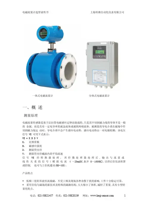
一、概述测量原理电磁流量传感器是基于法拉第电磁感应定律而制成的,只是其中切割磁力线的导体不是一般的金属,而是具有一定电导率的液态流体或液固两相流体。
被测量的导电介质在磁场中作切割磁力线运动时,导电介质中会产生感应电动势,感应电动势由一对电极检测,该电压信号VE 可用下式表示:VE =K B D V K:比例常数B:磁感应强度D:测量管内径V:测量管内径截面内的平均流速信号VE 经转换器处理,再经微处理器处理后,输出与流量成线性关系的信号(模拟电流4~20mADC、脉冲0~1000HZ),以供后位仪表积算或控制,也可与上位机通讯(RS-485)。
产品特点*低频三值矩形波恒流励磁,不受工频及现场各种杂散干扰的影响,工作十分稳定可靠。
*采用非均匀磁场的新技术及特殊的磁路结构,大大缩小了体积,减轻了重量,具有小型轻量化特点。
一体式电磁流量计分体式电磁流量计*具有隔离的RS485通讯功能,隔离的脉冲输出,微处理器能自动空管检测,空管复零。
*在现场可根据用户实际需要,在线修改量程、介质密度、流量单位等参数。
*无可动部件、无阻流部件,测量中几乎无附加压力损失。
*测量结果与流速分布、液体压力、温度、密度、粘度等物理参数无关。
*使用方便,安装后只需接上电源,即可使用。
瞬时、累计量直接中文显示于液晶屏上下两排。
应用领域由于电磁流量计有其独特的特点,因此被广泛应用于化工化纤、食品、造纸、制糖、矿冶、给排水、环保、水利水工、钢铁、石油、制药等工业领域中,用来测量各种酸、碱、盐溶液、泥浆、矿浆、纸浆、煤水浆、玉米浆、纤维浆、糖浆、石灰乳、污水、冷却原水、给排水、盐水、双氧水、啤酒、麦汁、各种饮料、黑液、绿液等导电流体介质的流量。
二、主要技术标准公称通径系列DN(mm)橡胶衬:32,40,50,65,80,100,125,150,200,250,300,350,400,450,500,600Po衬:5,8,10,15,20,25,32,40,50,65,80,100,125,150,200,250,300,350,400,450,500,600四氟衬:10,15,20,25,32,40,50,65,80,100,125,150,200,250,300,350,400,450,500,600精度等级0.5级,1.0级被测介质温度橡胶衬里:-20~+60℃;高温橡胶衬里:-20~90℃;聚四氟乙烯(PTFE)衬里:-25~+140℃;Po衬里:-30~+105℃额定工作压力DN10~DN65:2.5MPa;DN80~DN150:1.6MPa;DN200~DN600:1.0MPa*其它特殊压力(如6.4MPa)订货时请注明流量测量范围对应流速范围:0.05~10m/s电导率范围被测流体电导率不小于20us/cm输出信号及负载电阻电流信号:4-20mADC,0-750Ω;脉冲信号:0-1000Hz,占空比50%通讯信号(RS485)同类接口最多可接256个,并在电气上是完全隔离的。

OPTIFLUX 系列及其它技术数据表电磁流量计OPTIFLUX 1300 / 2300 / 4300 / 5300 / 6300 电磁流量计,拥有强大的自诊断功能,有各种安装接口,有各种衬里和电极材料,最高精度可达0.15%,重复性0.06% OPTIFLUX 2100 / 4100 电磁流量计(IFM 4080 升级换代产品,有自诊断功能)K300 一体型电磁流量计/ K 450K + F 电磁流量计高压电磁流量计科隆电磁流量计经济型K 300(一体型)模拟量K 450(一体或分体型)模拟量(带显示)特殊型OPTIFLUX 4040 C 两线制TIDALFLUX 4110 PF 非满管BATCHFLUX 5015 C 灌装式卫生型常用型W FOPTIFLUX 6300 C1. 性能简介1- 52. 常用产品2.1 OPTIFLUX 2300 / 4300 电磁流量计62.1 .1I FC 300 信号转换器6- 162.2 OPTIFLUX 2100 / 4100 电磁流量计172.2 .1I FC 100 信号转换器17- 2021- 22232425263. 经济型30- 313 .2K450K + F 电磁流量计32- 334. 选型与安装4.1传感器口径选择34- 354 .2电极形式 / 材料选择364.3衬里材料的选择374.4传感器在管线上的安装38- 416. 原理及标定证书44目录2.3 OPTIFLUX 2000/4000传感器2.4 IFS / 4000-HP 高压传感器2.5 IFM 3100K +F 电磁流量计2.6 OPTIFLUX 1300夹持型电磁流量计2.7 OPTIFLUX 5300 S W 陶瓷型夹持式电磁流量计2.7.1 OPTIFLUX 5300 FL 法兰型272.8 OPTIFLUX 6300 卫生接口型电磁流量计28- 293.1 K 300 一体型电磁流量计5. 产品选型编码42- 431. 性能简介OPTIFLUX 2300 / 4300 W(可选 C + F + R)DN 10 ~ 3000OPTIFLUX (一体)(墙挂分体)2100 / 4100 C + W DN 10 ~ 1200详细数据见P 6详细数据见P 17OPTI FLUX 2000(橡胶)/ OPTI FLUX 4000(四氟、PFA )+ / -0.3%±1mm / s (取决于传感器)OPTI FLUX 2000(橡胶)/ OPTI FLUX 4000(四氟、PFA )0.2% - 0.3%(液体中最多含30% 的固体成份)IFM 3100 / 3300 C + W1. 性能简介仪表性能同OPTIFLUX4100,传感器见M 900,见P 24K 300DN 10 ~ 300K 300≤1%详细数据见P 30DN 50 ~ 300M 900+ / -0.3% ±1mm / s(取决于传感器)K 4501. 性能简介DN 10 ~ 450 IFS4000≤0.5%DN 10 ~ 150 OPTIFLUX 1300 OPTIFLUX 10000.3%1. 性能简介OPTIFLUX 5300OPTIFLUX 63001. 性能简介OPTIFLUX 4040TIDALFLUX 4110 PFIFC 300 信号转换器1 图形显示器,背光(白)2 第1 行和第2 行用于显示不同的测量变量,大字体格式显示时只显示一个变量3 第三行显示条形图4 光感应键,无需打开盖就可操作信号转换器5 蓝色条显示:·测量模式时显示仪表位号·设置模式时显示菜单/ 功能名称6 X 指示有键按动7 指示红外线输出工作,此时4 光感应键失效8 连接KROHNE GDC 总线的插座9 光电感应接口,用于无线传送数据(输入/ 输出)IFC 300 显示 / 操作和调整键IFC 300 C 和IFC 300 F 的o 显示器可以隔90旋转2.1 IFC 300 信号转换器2.1 IFC 300 信号转换器使用特点·工厂设置(有二个记忆芯片,一个在机内,另一个在机芯外的底板上)·可以存储3组设定数据,factrory settings 为工厂设定数据用户不能更改(传感器的GK 值、满量程、零点、线圈阻值、温度等)机外底板上的记忆芯片机内记忆芯片·更换转换器时无需设置数据,直接从机芯外的底板上取出工厂设定数据。
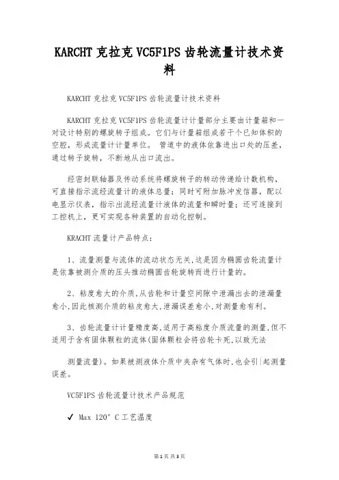
KARCHT克拉克VC5F1PS齿轮流量计技术资料KARCHT克拉克VC5F1PS齿轮流量计技术资料KARCHT克拉克VC5F1PS齿轮流量计计量部分主要由计量箱和一对设计特别的螺旋转子组成。
它们与计量箱组成若干个已知体积的空腔,形成流量计计量单位。
管道中的液体依靠进出口处的压差,通过转子旋转,不断地从出口流出。
经密封联轴器及传动系统将螺旋转子的转动传递给计数机构,可直接指示流经流量计的液体总量;同时可附加脉冲发信器,配以电显示仪表,指示出流经流量计液体的流量和瞬时量;还可连接到工控机上,更可实现各种装置的自动化控制。
KRACHT流量计产品特点:1、流量测量与流体的流动状态无关,这是因为椭圆齿轮流量计是依靠被测介质的压头推动椭圆齿轮旋转而进行计量的。
2、粘度愈大的介质,从齿轮和计量空间隙中泄漏出去的泄漏量愈小,因此核测介质的粘皮愈大,泄漏误差愈小,对测量愈有利。
3、齿轮流量计计量精度高,适用于高粘度介质流量的测量,但不适用于含有固体颗粒的流体(固体颗粒会将齿轮卡死,以致无法测量流量)。
如果被测液体介质中夹杂有气体时,也会引|起测量误差。
VC5F1PS齿轮流量计技术产品规范✔Max 120°C工艺温度✔ Max 350 bar工艺压力✔适用于所有粘性、非研磨性液体VC5F1PS齿轮流量计产品亮点✔低噪音和低重量✔经济高效的运行✔选项:脉冲输出、继电器、模拟输出、累积量、触点开关、批处理、插入式LED显示器。
安装要求说明:1.必须根据适用的技术规则进行设备的安装和监控。
在安装和操作系统时,必须遵守相关指令,标准等的要求。
2.仅允许在规定的环境和环境条件下操作。
3.仅在符合适用指令和国家法规所有要求的潜在爆炸性环境中使用配件4.通过与其他组件,保护系统和设备进行组装,不会发生新的着火危险。
5.在正常操作期间,设备内部不得存在爆炸性混合物,否则会有区域残留物。
6.如果系统中可能发生泄漏,则可能需要考虑区域延迟。
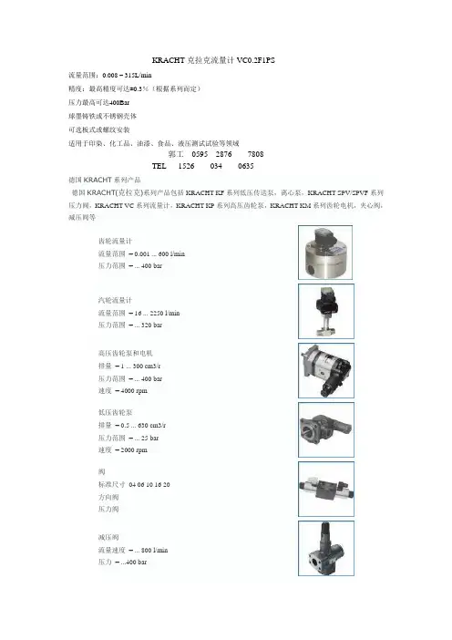
KRACHT克拉克流量计VC0.2F1PS
流量范围:0.008 – 315L/min
精度:最高精度可达±0.3%(根据系列而定)
压力最高可达400Bar
球墨铸铁或不锈钢壳体
可选板式或螺纹安装
适用于印染、化工品、油漆、食品、液压测试试验等领域
郭工0595 2876 7808
TEL 1526 034 0635
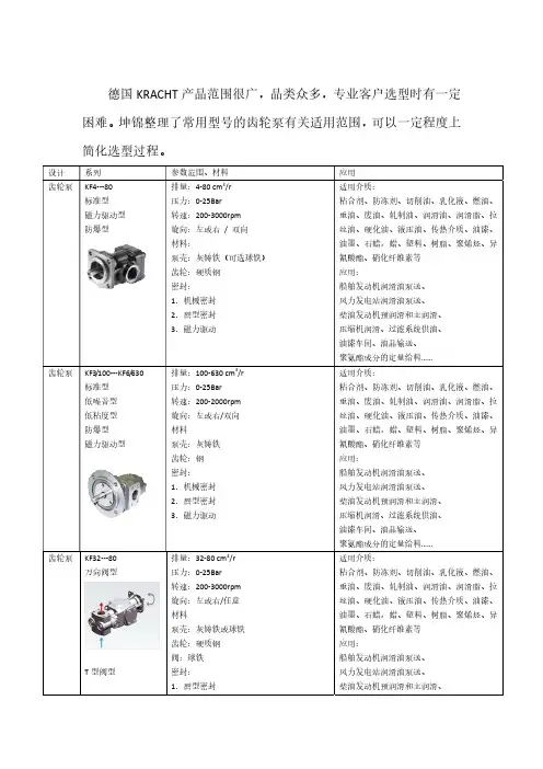
德国KRACHT系列产品
德国KRACHT(克拉克)系列产品包括KRACHT KF系列低压传送泵,离心泵,KRACHT SPV/SPVF系列压力阀,KRACHT VC系列流量计,KRACHT KP系列高压齿轮泵,KRACHT KM系列齿轮电机,夹心阀,减压阀等
齿轮流量计
流量范围= 0.001 ... 600 l/min
压力范围= ... 400 bar
汽轮流量计
流量范围= 16 ... 2250 l/min
压力范围= ... 320 bar
高压齿轮泵和电机
排量= 1 ... 300 cm3/r
压力范围= ... 400 bar
速度= 4000 rpm
低压齿轮泵
排量= 0.5 ... 630 cm3/r
压力范围= ... 25 bar
速度= 2000 rpm
阀
标准尺寸04 06 10 16 20
方向阀
压力阀
减压阀
流量速度= ... 800 l/min
压力= ...400 bar
操作压力= ... 350 bar
活塞尺寸= 40 ... 250 mm。
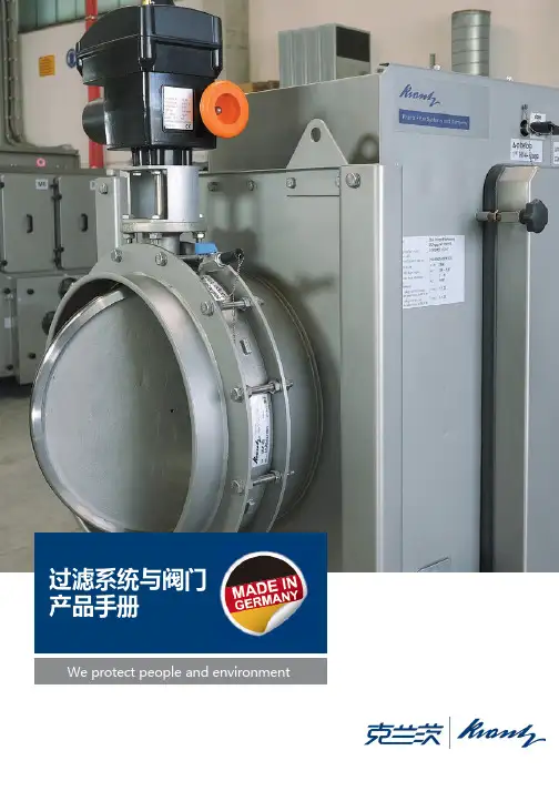
产品手册We protect people and environmentKrantz从传统,致力于未来在标准的现成解决方案不足的情况下,Krantz提供量身定制的服务:•核电站•核研究中心•核通风系统•放射性废物和放射性废物处理厂的储存设施•核燃料元件的生产和加工•退役核设施•面向问题的解决方案•BSL-3和BSL-4实验室•化学工业•制药业•医院•公共卫生保健•纺织工业的通风技术•I&C工程•技术服务我们的产品范围包括规划,开发,工程,设计,交付,安装和调试。
目录过滤系统过滤器安全更换机箱SCF classic 4过滤器安全更换机箱带扫描的过滤器安全SCF hightec 更换机箱SCF hightec Triple S过滤器安全更换机箱System Nuclear Karlsruhe 5移动式过滤装置MFU classic and MFU hightec 可清洗移动HEPA 过滤器系统RHF hightec 吸附过滤器吸附过滤器CFH class CFH hightec6阀门系统圆形气密截止阀GD-C 7矩形气密截止阀GD-R 矩形气密截止阀S 压力缓冲阀RK-F108止回阀RK-E20百叶阀门–气密型号LD-J –气密型号ND-J 泄压阀KL-E...9配件检漏装置LT-D10热封装置HS-D classic资质11过滤器安全更换机箱SCF classic用于从排气系统中分离出可能被放射性或生物污染的空气微粒和气溶胶。
特征:•材质:不锈钢•垂直流动方向•设计紧凑,模块化,可扩展为过滤器组,额定风量为6665 l/s[24000 m3/h]•可使用安全更换技术无污染地更换过滤器•可采用不同的预过滤器和HEPA 过滤器的组合方式•通过测试槽检测每个HEPA 过滤单元的密封完整性•通过可自动调节的弹簧系统夹紧HEPA 过滤单元过滤系统过滤器安全更换机箱SCF hightec用于从排气系统中分离出可能被放射性或生物污染的空气微粒和气溶胶。

WH-7CNumber of No. of Flow Feet of Size ApartmentsWH-7C(GPM)HeadManifold2-10 1 7 20 3/4" 11-38 2 14 20 1" 39-66 3 21 20 1 1/4" 67-94 4 28 20 1 1/2" 95-122 5 35 20 11/2" 123-150 6 42 20 2"For number of 7C’s, y =.053T+1.7 (note: round down)WHS-60CZDWNumber of No. of Flow Feet of Size ApartmentsWHS-60CZDW(GPM)HeadManifold2-16 1 10 20 1" 17-70 2 21 20 11/2" 71-115 3 31 20 11/2" 116-160 4 42 20 2" 161-200 5 52 20 2vFor number of 60C’s, y = .043T+1.62 (note: round down)Job Site Information:Present Water Heating EquipmentType of Heater: o Instantaneous o Indirect o Direct Fired Make and Model __________________________________ Storage Volume ________________________________Gal. Recovery ________________________________________ Fuel ____________________________________________ Operating Temp. __________________________________ Boiler Make and Model _____________________________ BTU’s ___________________________________________ Avg. Boiler Water Temp. ____________________________ Recirculating Line Size _____________________________ Circulator Make and Model __________________________ Control __________________________________________ Are there any problems with the present hot water? ______OptionsWill new boiler be installed? _________________________ For hot water only? ________________________________ If no, will old boiler be used for both hot water and heat? ___ *If for hot water and heating, what is the space heating load? ____________BTU’sSizing Information Input:• Number of Apartments, A• Average number of People per Apartment, PSizing Commercial Premier Modules for Elderly Housing• Determine usage as minimal, 11/4 persons with private kitchen facili-ties; or average,11/2 persons and/or with central dining facilities.• Select proper number of WH-7C modules from Table 1 and the required heat generator capacity from Figure 1.Recommendations:• Number_________ Models _____________• Flow (GPM) _________________________• Feet of Head ________________________• Size Manifold ________________________R e q u i r e d M B H I n p u t t o P r e m i e r U n i t sNumber of Housing Units04080120160200240280200400600800 Figure 1. Required Heat Generator Capacity - MBHA ve r a ge Us a geJob Site Information:Present Water Heating EquipmentType of Heater: o Instantaneous o Indirect o Direct Fired Make and Model __________________________________ Storage Volume ________________________________Gal. Recovery ________________________________________Fuel ____________________________________________ Operating Temp. __________________________________ Boiler Make and Model _____________________________BTU’s ___________________________________________ Avg. Boiler Water Temp. ____________________________ Recirculating Line Size _____________________________ Circulator Make and Model __________________________Control __________________________________________ Are there any problems with the present hot water? ______OptionsWill new boiler be installed? _________________________ For hot water only? ________________________________If no, will old boiler be used for both hot water and heat? ___*If for hot water and heating, what is the space heating load? ____________BTU’sSizing InformationInput:• Number of Apartments, A• Average number of People per Apartment, PSizing Commercial Premier Modulesfor Apartment Buildings• Determine whether the apartment building usage should be classified as minimal, small shower head, 2 to 3 GPM,21/2 persons average occupancy; or average regular shower heads, 4 to 6 GPM, 3 to 4 persons per apartment.• Select proper number of WH-7C modules from Table 1 and the required heat generator capacity from Figure 1. Recommendations:• Number_________ Models _____________• Flow (GPM) _________________________• Feet of Head ________________________• Size Manifold ________________________WH-7CNumber of No. of Flow Feet of SizeApartments WH-7C (GPM) Head Manifold 2-5 1 7 20 3/4"6-25 2 14 20 1" 26-44 3 21 20 11/4"46-63 4 28 20 11/2"64-82 5 35 20 11/2"83-100 6 42 20 2" For number of 7C’s, y =.053T+1.7 (note: round down)WHS-60CZDWNumber of No. of Flow Feet of SizeApartments WHS-60CZDW (GPM) Head Manifold 2-8 1 10 20 1"9-32 2 21 20 11/2"33-55 3 31 20 11/2"56-79 4 42 20 2"80-105 5 52 20 2"For number of 60C’s, y = .043T+1.62 (note: round down)RequiredMBHInputtoPremierUnitsNumber of Apartment Units020406080100120140 200400600800Figure 1. Required Heat Generator Capacity - MBHA ve r ag eU sa geJob Site Information:Present Water Heating EquipmentType of Heater: o Instantaneous o Indirect o Direct Fired Make and Model __________________________________ Storage Volume ________________________________Gal. Recovery ________________________________________ Fuel ____________________________________________ Operating Temp. __________________________________ Boiler Make and Model _____________________________ BTU’s ___________________________________________ Avg. Boiler Water Temp. ____________________________ Recirculating Line Size _____________________________ Circulator Make and Model __________________________ Control __________________________________________ Are there any problems with the present hot water? ______ OptionsWill new boiler be installed? _________________________ For hot water only? ________________________________ If no, will old boiler be used for both hot water and heat? ___ *If for hot water and heating, what is the space heating load? ____________BTU’sSizing InformationInput:• Number of Rooms, A• Average number of Occupants per Room, PSizing Commercial Premier Modules for Motels • Determine whether the motel should be classified asminimal, small shower head, 11/2persons typical occupancy;or average, regular shower heads 4-6 GPM, 2 persons perroom (convention motel with scheduled meetings or tourbuses with scheduled departures).• Select proper number of WH-7C modules from Table 1and the required heat generator capacity from Figure 1.• Laundry and food service are not included, these loadsshould be calculated separately.Recommendations:• Number_________ Models _____________• Flow (GPM) _________________________• Feet of Head ________________________• Size Manifold________________________WH-7CNumber of No. of Flow Feet of SizeRooms WH-7C (GPM) Head Manifold 2-5 1 7 20 3/4"6-25 2 14 20 1" 26-44 3 21 20 11/4"45-63 4 28 20 11/2"64-82 5 35 20 11/2"83-100 6 42 20 2" For number of 7C’s, y =.053T+1.7 (note: round down)WHS-60CZDWNumber of No. of Flow Feet of SizeRooms WHS-60CZDW (GPM) Head Manifold 2-9 1 10 20 1"10-37 2 21 20 11/2"38-62 3 31 20 11/2"63-194 4 42 20 2"95-128 5 52 20 2" For number of 60C’s, y = .043T+1.62 (note: round down)RequiredMBHInputtoPremierUnitsNumber of Units0255075100125150175 200400600800Figure 1. Required Heat Generator Capacity - MBHA ve r ag eU sa ge• Sizing InformationMachine Gallons Cycle Per Gallons Type/Model Quantity Per Cycle Hour* Per Hourx x=x x=x x=x x=x x=Total # Total GalsMachines Per Cycle Total GPH Load**Corrected Total * If Cycle Per Hour Date is not available, use 1.5.** Calculation based on a 40°F inlet water temperature.Use the correction factors on the right for other inlet water temperatures: Inlet Water Temperature Multiply Total GPH Load by:50° F 0.9060° F 0.8070° F 0.70• Determining Storage VolumeSizing Commercial Premier forCoin Operated LaundryDiversification TableThe number of machines drawing water at any one time varies widely.From the table below, determine the applicable diversification factorto use for this application.Total No. Machines Factor (D.F.)1-12 100%13-24 80%25-36 60%37-48 50%Calculation:Total Storage RequiredTotal gals/cycle x D.F.Selection of ModelsCalculation:Total Storage ÷ Number of Units = Storage Tank GallonStorage Tank Gallon Premier Models0-41 WH-7C’s42-60 WH-60C’s61-80 WH-80C’s81-120 WH-120C’s120+RequiredMBHInputtoPremierUnitsTotal GPH LoadNumberofUnits123456 0200400600800100012001400160020040060080010001200Figure 1. For Required MBTU/hrSizing based on recovery from 50° to 150° F plus storage.IntroductionThere are two installation conditions that must be considered when sizing a heat generator/commercial Premier installation:A. When the heat generator is to work with the Premier to provide service hot water load only .B. When there are commercial applications that require sizing the heat generator for the combined space heating and service hot water loads the heat generator must be large enough to accommodate both loads. However, since both peaks do not occur simultaneously, it is advantageous to take diversity factors into consideration in sizing, since unnecessarily large equipment is wasteful of energy.The following guide will provide a “rule of thumb” method of estimation the additional heat generating capacity required for service hot water heating on typical Premier installations.NOTE: This guide is to be used in conjunction with Figure 1 from AMTROL’s Commercial Evaluation and Sizing Forms for:1. Apartment Houses2. Motels3. Nursing Homes4. Coin Operated LaundryA. Service Hot Water Load OnlyThe heat generator installed to take care of the service hot water load only must meet the minimum capacity shown in the Evaluation and Sizing Forms for the particular application.B. Space Heating and Service Hot Water Loads CombinedThe factors which affect sizing for this type of installation are:1. The piping and pickup losses which are typically applied when a boiler is installed only for space heating.2. The number of hours of occurrence of temperatures anywhere near design temperatures for space heating represent an extremely low percentage of the total hours in the heating season.3. The maximum space heating requirements do not occur at the time of day when the maximum peak service demands occur.4. Service hot water heating equipment must be sized to supply the maximum rate of use for various periods of time from a few minutes to any hour or longer, and since these periods differ from day to day, and from month to month, the design capacity is significantly greater that that required for the vast majority of hours of service hot water usage.Rule-of-Thumb Estimating MethodThe factors shown provide a “rule-of-thumb” method for estimating the additional heat generating capacity required for service hot water heating on typical installations. The first is to calculate the ratio of maximum service hot water load to the gross output for space heating (including the normal allowance for piping and pickup). From Figure 2 determine the equivalent factor - this is multiplied by the service hot water load, and the product added to the gross space heating load, to determine the total heat generator capacity.EXAMPLE: 50 unit apartment, gross output required for space heating is 1,100,000 btu/h. Service hot water usage is minimal. Step 1. From Figure 1, Curve I, required for capacity for service hot water = 330,000 btu/h Step 2. The ratio of service hot water capacity to gross space heating capacity:Maximum service hot water load 333,000Gross space heating = 1,100,000 = 0.3Step 3. From Figure 2, factor = 0.2 0.2 x 330,000 = 66,000 btu/hStep 4. Size of heat generator for combined service hot water and space heating loads: 1,100,000 + 66,000 = 1,166,000 btu/hRATIOFACTOR.25.30.40.50.751.01.52.03.04.05.00.20.40.50.65.75.80.85.90.95 1.0TYPICAL MODULAR INSTALLATIONPREMIER PREMIER PREMIERPREMIER returnPREMIER SUPPLY。
FTB 372 SeriesAxial Turbine Flow Meter- 2 -Table of contents page 0About this operating manual (4)1Device description (5)1.1Intended use (6)2Safety instructions (6)3Important notes to installation and operation (7)4Installation in piping (8)5Electrical connection (9)6Replacement of turbine insert (9)7Cleaning of the flow meter (10)8Disassembly and disposal (11)9Technical data (12)9.1FTB 372 with pulse output (12)9.1.1Hall sensor VTH output signal characteristics (13)9.2Characteristic curves, pressure drop (13)9.3Materials table (14)9.4Dimensions (14)Copyright notice:The reproduction, distribution and utilization of this operating manual as well as the communication of its contents to others without express authorization is prohibited. Offenders will be held liable for the payment of damages. All rights reserved in the event of the grant of a patent, utility model or design. Technical changes reserved - 3 -About this operating manual Series FTB 372- 4 -0 About this operating manual• The operating manual is aimed at specialists and semi-skilled personnel.• Before each step, read through the relevant advice carefully and keep to the specified order.•Thoroughly read and understand the information in the section "Safety instructions".If you have any problems or questions, please contact your supplier or contact us directly at:One Omega Drive, P.O. Box 4047Stamford, CT 06907-0047 Tel: (203) 359-1660 e-mail:**************Hazard signs and other symbols used:CAUTION! Electric current!This sign indicates dangers which could arise from handling of electric current.WARNING! / CAUTION! Risk of injury!This sign indicates dangers that cause personal injuries that can lead to health defects or cause considerable damage to property. CAUTION! Material damage!This sign indicates actions which could lead to possible damage to material or environmental damage.ADHERE TO OPERATING MANUAL! NOTICE!This symbol indicates important notices, tips or information. NO DOMESTIC WASTE!The device must not be disposed of together with domestic waste.Pay attention to and comply withinformation that is marked with this symbol.Follow the specified instructions and steps.Adhere to the given order.❑Check the specified points or notices.Reference to another section, document orsource. • Item.Series FTB 372 Device descriptionTechnical changes reserved - 5 -1 Device descriptionThe flow meter of the series FTB 372 from OMEGA ENGINEERING INC. is a transducer for flow rate and total flow measurement.It has an almost unlimited application through its exceptionally compact design, its very wide measurement range and its convincing measurement accuracy.Flow meter components FTB 372:Functional principle:The liquid flowing into the flow meter is divided by the guiding blades in four split beams. These hit the rotor from four directions and put it inmotion. The uniform loading of bearing from foursides causes the forces to cancel themselves out for the most part and wear is reduced to a minimum.The extremely hard bearing materials, sapphire and hard metal, ensure in addition an extraordinary life expectancy.The rotor speed is transmitted to an electrical pulse signal (frequency):•The FTB 372 is equipped with magnets onthe rotor. A Hall-Effect sensor detects the rotation of the rotor.A flow-proportional frequency signal (square wave signal) is provided.Safety instructions Series FTB 372- 6 -1.1 Intended useThe flow meter of the series FTB 372 may only be used for flow rate measurements or dosing of liquids. Never use them for gas measurements.WARNING! No safety component!The flow meter of the series FTB 372 is not a safety component in accordance with Directive 2006/42/EC (Machine Directive). Never use the FTB 372 as a safety component.The operational safety of the device supplied is only guaranteed by intended use. The specified limits (♑ § 9 "Technical data") may under no circumstances be exceeded.Before ordering and installation, check that the material of the turbine flow monitor is suitable to the medium to be measured and the application (♑ § 9.3 "Materials table").2Safety instructionsBefore you install the FTB 372, read through this operating manual carefully. If the instructions contained within it are not followed, in particular the safety guidelines, this could result in danger for people, the environment, and the device and the system it isconnected to.The FTB 372 corresponds to the state-of-the-art technology. This concerns the accuracy, the operating mode and the safe operation of the device.In order to guarantee that the device operates safely, the operator must act competently and be conscious of safety issues.OMEGA ENGINEERING INC. provides support for the use of its products either personally or via relevant literature. The customer verifies that our product is fit for purpose based on our technical information. The customer performs customer- and application-specific tests to ensure that the product is suitable for the intended use. With this verification all hazards and risks are transferred to our customers; our warranty is not valid.Qualified personnel:The personnel who are charged for the installation, operation and maintenance of the FTB 372 must hold a relevant qualification. This can be based on training or relevanttuition.The personnel must be aware of this operating manual and have access to it at all times. The electrical connection should only be carried out by a fully qualified electrician.General safety instructions:In all work, the existing national regulations for accident prevention and safety in the workplace must be complied with. Any internal regulations of the operator must also be complied with, even if these are not mentioned in this manual.You can mount the flow meter in any position. If it is installed into vertical pipes, the flow direction is preferably upwards. You must avoid a free outlet.Series FTB 372Important notes to installation and operationTechnical changes reserved - 7 -The arrow which is placed on the flow meter(→) shows the only permitted flow direction. For precise measurement, the length of the in- and outlet tubes must be observed(♑§ 3 "Important notes to installation and operation").The internal diameter of the in- and outlet tube must correspond with the internal diameterof the turbine flow monitor.The flow medium to be monitored should preferably contain as few solid particles aspossible. Present particles must not exceed a diameter of 0.63 mm. If necessary, install ascreen filter.Avoid absolutely the formation of gas bubbles or cavitation in the medium by takingproper measures.The material of the series FTB 372 is not suitable for monitoring oils. The strength of theused plastic parts would be considerably reduced.In order to clean the flow monitor of contaminations, flush the unit reverse to the flow direction (♑§ 7 "Cleaning of the flow meter").Suitable measures should be taken to prevent the medium from freezing.A possible blowing out of the device FTB 372 must take place only in opposite direction tothe flow.We recommend to use only screened connection cables. Connect the shield on one side (the wire ends) on ground.Attention:The union nut of the sensor (Hall-Effect-Sensor or inductive proximity switch) is sealed and must not be opened!When you still open this component, the fixation of the turbine system is disturbed and it will be damaged.Special safety instructions:Warnings that are specifically relevant to individual operating procedures or activities can be found at the beginning of the relevant sections of this operating manual.3 Important notes to installation and operationObserve the following instructions in order to achieve highest-possible measurement accuracy and specified output signal:• Before installing the turbine flow monitor flush the pipe carefully. You avoid a blocking ofthe turbine caused by particles from the pipe installation.• The installation position of the flow monitor is unreserved. If it is installed into verticalpipes, the flow direction is preferably from below upward. You must avoid a free outlet. • The arrow which is placed on the flow monitor (→) shows the only permitted flowdirection.Installation in pipingSeries FTB 372- 8 -•In order to achieve the best measurement accuracy, a straight tube in front of the flow monitor must be retained, min 10 x DN. Behind the flow monitor, a straight outlet tube of 5 x DN must be kept.The internal diameter of the in- and outlet tubes must correspond with the internaldiameter of the flow monitor. Before and behind the stabilization tubes, the line may be contracted or enlarged.In practice these instructions often can not be observed. Then the pulse rate and the measurement accuracy can be affected.•The flow medium to be monitored should preferably contain as few solid particles as possible. Present particles must not exceed a diameter of 0.63 mm. If necessary, install a screen filter!• The material of the series FTB 372 is not suitable for monitoring oils. The strength of the used plastic parts would be considerably reduced. •Attention:The union nut of the sensor (Hall-Effect-Sensor or inductive proximity switch) is sealed and must not be opened!When you still open this component, the fixation of the turbine system is disturbed and it will be damaged.4 Installation in pipingNow you can install the flow meter in the piping system which was prepared according to § 3. Note:•Use only a suitable compound for sealing.If you seal the male thread, take care that no fibrous sealing compounds get into the turbine (hemp or Teflon strip).Installation with connecting adapter:At first screw-in the connecting adaptors into the tube.Now install the turbine. Make sure that the provided seals fit properly and tighten theunion nuts.Series FTB 372 Electrical connectionTechnical changes reserved- 9 -5 Electrical connectionAttention: We recommend to use only screened cables. Connect the shield on one side (the wire ends) on ground.FTB 372 with pulse outputThe output signal of the flow meter is a flow-proportional frequency signal. The shape of the signal is a square wave and its amplitude corresponds approximately with the supply voltage. It is an open collector signal, NPN- or PNP-switching.The connected electronic instrument should have a loading resistance (pull-up or pull-down resistor) of 5 k Ω in the inlet.Schematic representation:A connection is made with three leads, the supply voltage must be connected between +Uassignment of the supply cables can be taken from the sketch on the type plate. FTB 372 with connecting cable:Colour code:BN = brownGN = greenWH = white R = resistor6 Replacement of turbine insertDismount the flow sensor. The sensor housing (Hall-Effect-Sensor or inductive proximityswitch) is sealed and must not be opened.Press the turbine insert out of the tube piece in flow direction using a flat tool.The insert fits very tight in the tube piece. You should not use your fingers and never use a pointed tool to press it out of the tube.The turbine insert consists of two cylinders of different diameters which must never bedismounted.Push the new insert with the small diameter to the front into the pipe section against theflow direction. Turn the insert in such a way that the webs are not directly beneath the Hall sensor or the proximity switch. Press the insert into the pipe section up to the stop. The position will be correct, if the face of the inserts is flush with the pipe section (applies only for metallic version). Plastic version: push the insert up to the stop, now do the same with the spacer. The spacer must be flush with the tube piece.Reinstall the Turbotron in the piping. Make sure that the provided seals fit properly.Cleaning of the flow meter Series FTB 372- 10 -7 Cleaning of the flow meterAttention:The union nut of the sensor is sealed and must not be opened!To remove dirt from the flow meter, you should flush itwith water reverse to the flow direction.• Warning:Blowing out the FTB 372 can damage the turbine bearing. Never blow them free with compressed air.Series FTB 372 Disassembly and disposal8 Disassembly and disposalCAUTION! Risk of injury!Never remove the device from a plant in operation. Make sure that the plant is shut down professionally.Before disassembly:Prior to disassembly, ensure that❒ the equipment is switched off and is in a safe and de-energised state. ❒ the equipment is depressurised and has cooled down. Disassembly:Remove the electrical connectors.Remove the FTB 372 using suitable tools.Disposal:NO HOUSEHOLD WASTE!The FTB 372 consists of various different materials. It must not be disposed of with household waste.Take the FTB 372 to your local recycling plantorsend the FTB 372 back to your supplier or toOMEGA ENGINEERING INC..Technical data Series FTB 3729 Technical dataThe technical data of customised versions may differ from the data in these instructions. Please observe the information specified on the type plate.9.1 FTB 372 with pulse outputeffect of deviations from mentioned values.Series FTB 372Technical data9.1.1 Hall sensor VTH output signal characteristicsTemperature dependencyClosed output transistor: Voltage limitationLoad current9.2 Characteristic curves, pressure dropCharacteristic curves: Pressure drop:Technical data Series FTB 372 9.3 Materials table9.4 DimensionsFTB 372 MS-180 with connecting adapterSeries FTB 372Series FTB 372 M-5662/0717。
电磁流量计选型设计资料10/2006 KROHNEIFM 4300 IFM 4080K 300 K 450 OPTIFLUX 6300 OPTIFLUX 13001. 科隆电磁流量计2. 产品性能简介3. 常用产品详细介绍3.1 IFM 4300电磁流量计 3.1.1 IFC 300信号转换器 3.1.1.1 显示/操作和调整键 3.1.1.2 诊断功能 3.1.1.3 使用特点 3.1.1.4 尺寸和重量 3.1.1.5 接线图 3.1.1.6 产品精度表 3.1.2 IFS 4300 (OPTIFLUX 4000)电磁流量传感器 3.1.2.1 常用规格 3.1.2.2 外形图及尺寸 3.1.2.3 特殊规格3.2 IFM 4080K+F电磁流量计 3.2.1 IFC 090K+F信号转换器 3.2.1.1 面板及外形尺寸 3.2.1.2 技术数据 3.2.1.3 接线图 3.2.2 IFS 4000电磁流量传感器 3.2.2.1 常用规格 3.2.2.2 外形图及尺寸3.3 IFS 3080 K+F 电磁流量计 3.3.1 M 900 尺寸和重量 3.3.2 IFM 3080 K 尺寸和重量3.4 IFC 010 电磁流量转换器 3.4.1 外形尺寸 3.4.2 接线图128888991011181919202122222223242626272828283030313233343.5 OPTIFLUX 1300 夹持型电磁流量计 3.5.1 外形图 3.5.2 尺寸及重量3.8 OPTIFLUX 5300 陶瓷型电磁流量计 3.8.1 OPTIFLUX 5300SW 夹持型电磁流量计 3.8.1.1 外形图 3.8.1.2 尺寸和重量3.8.2 OPTIFLUX 5300FL 法兰型电磁流量计 3.8.2.1 外形图 3.8.2.2 尺寸和重量3.9 OPTIFLUX 6300 卫生接口型电磁流量计 3.9.1外形图及尺寸 353536373738393940414242434445474747484949505151515152545456575862 4. 经济型产品详细介绍 4.1 K300一体型电磁流量计 4.1.1 接线图 4.1.2 尺寸及重量 4.2 K450K+F电磁流量计 4.2.1 接线图 4.2.2 尺寸及重量5. 特殊型产品详细介绍 5.1 WATERFLUX 2070电池供电电磁流量计 5.1.1 特性 5.1.2 行业应用 5.1.3 外形图及尺寸6. 选型安装 6.1 传感器口径选择 6.2 电极形式/材料选择 6.3 衬里材料的选择 6.4 传感器在管线上的安装7. 产品选型编码3.6OPTIFLUX2300电磁流量计 3.6.1 OPTIFLUX 2000 电磁流量传感器尺寸及重量 3.7 OPTIFLUX 4300 电磁流量计 3.7.1 OPTIFLUX 4000 电磁流量传感器尺寸及重量 3.6.2 外形图及尺寸 3.7.2 外形图及尺寸科隆电磁流量计经济型K 300模拟量K 450模拟量(带显示)特殊型OPTIFLUX 4040 C 两线制TIDALFLUX 4110 PF非满管BATCHFLUX 5015 C灌装式WATERFLUX 2070电池供电OPTIFLUX 7300 C电容式常用型C F W F C W(配IFC 300、010)2. 产品性能简介+F+WIFM 4080 K+F(IFM 4080K-Ex)IFM 4300 C详细数据见 P8详细数据见 P22IFM 3080 K+F2. 产品性能简介详细数据见 P30仪表性能同 IFM 4080,传感器见 M 900,见 P28贸易计量认证详细数据见 P47详细数据见 P492. 产品性能简介OPTIFLUX 1300OPTIFLUX 2300OPTIFLUX 43002. 产品性能简介300OPTIFLUX 52. 产品性能简介IFC 300 信号转换器1 图形显示器,背光(白)2 第1行和第2行用于显示不同的测量变量,大字体格式显示 时只显示一个变量3 第三行显示条形图4 光感应键,无需打开盖就可操作信号转换器5 蓝色条显示: ·测量模式时显示仪表位号 ·设置模式时显示菜单/功能名称6 X指示有键按动7 指示在状态列表中有信息示红外线输出工作,此时4光感应键失效8 连接KROHNE GDC 总线的插座9 光电感应接口,用于无线传送数据(输入/输出)3.1.1.1 IFC 300 显示/操作和调整键IFC 300 C和IFC 300 F的0显示器可以隔90旋转3.1.1.3 使用特点·工厂设置(有二个记忆芯片,一个在机内,另一个在机芯外的底板上)·可以存储3组设定数据,除了工厂设定数据用户不能更改外(传感器的GK值、满量程、零点、线圈阻值、温度等)机外底板上的记忆芯片机内记忆芯片·更换转换器时无需设置数据,直接从机芯外的底板上调出数据。
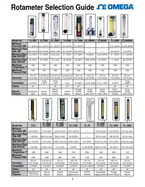
SERIESLFMALFMBLFMCLFMDLFMELFMFRanges 0.1 to 5 GPM water (0.5 to 18 LPM water)0.1 to 5 GPM water (0.5 to 18 LPM water)0.25 to 8 GPM water (1 to 30 LPM water)0.8 to 10 GPM water (3 to 40 LPM water)1.2 to 25 GPM water (5 to 100 LPM water)2.5 to 70 GPM water (10 to 250 LPM water)Accuracy±5% FS±5% FS±5% FS±5% FS±5% FS±5% FSBody MaterialsPolycarbonatePolycarbonatePolycarbonatePolycarbonatePolycarbonatePolycarbonateProcess Connection 1/2˝ male NPT in-line or 90° elbow connections 1/2˝ male NPT in-line or 90° elbow connections 1/2˝ or 3/4˝ male NPT in-line or 1/2˝ male NPT 90° elbow connections 3/4˝ male or female NPT in-line or 3/4˝ male NPT 90° elbow connections 1˝ male or female NPT in-line or 1˝ male NPT 90° elbow connections 2˝ male or female NPT in-line connections Scale Length2˝ (51 mm)3˝ (76 mm)3˝ (76 mm)3.5˝ (89 mm)4.5˝ (114 mm)5.5˝ (140 mm)SERIESRMARMBRMCVFAVFBVFC/VFCRRanges0.05 to 200 SCFH air (5 to 2500 cc/m air)1 to 50 GPH water (5 to 300 cc/m water)0.5 to 600 SCFH air (0.6 to 95 LPM air)1 to 100 GPH water (0.06 to 6.2 LPM water) 5 to 1800 SCFH air (2.5 to 850 LPM air)0.1 to 10 GPM water (0.05 to 5 LPM water)0.1 to 200 SCFH air (0.06 to 100 LPM air)0.6 to 40 GPH water (6 to 200 cc/m water)0.3 to 200 SCFH air (0.2 to 40 LPM air)0.5 GPH to 5 GPM water (0.002 to 20 LPM water) 2.5 to 100 SCFM air (60 to 2800 LPM air)0.5 to 20 GPM water (2 to 75 LPM water)Accuracy±4% FS±3% FS±2% FS±5% FS ±3% FS ±2% FS Body MaterialsPolycarbonate Polycarbonate Polycarbonate AcrylicAcrylicAcrylicTemperature Limits 130°F (54°C)130°F (54°C)130°F (54°C)With valve: 120°F (48°C); Without valve: 100°F (38.6°C)With valve: 120°F (48°C);Without valve: 100°F (38°C)120°F (48°C)Pressure Limits100 psi (6.7 bar)100 psi (6.7 bar)100 psi (6.7 bar)With valve: 100 psi (6.7 bar);Without valve: 150 psi (10 bar)With valve: 100 psi (6.7 bar);Without valve: 150 psi (10 bar)100 psi (6.7 bar)Process Connection 1/8˝ female NPT back connections 1/4˝ female NPT back connections1/2˝ female NPT back connections1/8˝ female NPT back or end connections1/8˝ female NPT back or end connections 1˝ female or male NPT or BSPT back or end connections (VFC only)Scale Length 2˝ (51 mm)5˝ (127 mm)10˝ (254 mm)2˝ (51 mm)4˝ (102 mm)5˝ (127 mm)Metering ValveOptional bottom or top mount brass or stainless steel valveOptional bottom brass or stainless steel valveOptional bottom brass or stainless steel valveOptional bottom or top mount brass or stainless steel valveOptional bottom brass or stainless steel valveVFCR standard with Delrin ® plastic full adjust and control valveGENERAL PURPOSE IN-LINEFlowmetersINDUSTRIALFlowmetersSERIESVATTVAVA1000 VA1500VA20000VA25000DR10000DR20000Ranges1.19 to 79 GPH water (75 to 5000 ml/min water)6.34 to 79.2 GPH water (400 to 5000 ml/min water)0.104 to 89.2 SCFH air (49 to 42000 ml/m air)0.009 to 19.97 GPH water (0.55 to 1260 ml/m water)0.22 to 49 SCFH air(104 to 23100 ml/min air)0.028 to 27 GPH water (1.8 to 522 ml/min water)0.792 to 93.9 SCFH air (374 to 44300 ml/min air)0.087 to 21.7 GPH water (5.5 to 1370 ml/m water)0.104 to 18.39 SCFH air (49 to 8600 ml/m air)0.01 to 3.32 GPH water (0.61 to 209 ml/min water)0.24 to 100 SCFH air (0.13 to 50 LPM air)0.02 to 24 GPH water (1.5 to 1500 cc/m water)0.33 to 90 SCFH air (0.16 to 44 LPM air)0.05 to 21 GPH water (3.2 to 1300 cc/m water)Accuracy±5% FS ±5% FS ±2% FS ±2% FS±2% FS±2% FS±5% FS±5% FSBody MaterialsPFA PFA Glass flow tube Glass flow tube Glass flow tube Glass flow tube Glass flow tube Glass flow tube Temperature Limits 250°F (121°C)250°F (121°C)250°F (121°C)150°F (65°C)250°F (121°C)150°F (65°C)250°F (121°C)250°F (121°C)Pressure Limits100 psi (6.7 bar)100 psi (6.7 bar)200 psi (13.8 bar)100 psi (6.7 bar)200 psi (13.8 bar)100 psi (6.7 bar)250 psi (17 bar)250 psi (17 bar)Process Connection 1/4˝ or 3/8˝ female NPT back connections 1/4˝ or 3/8˝ female NPT back connections 1/8˝ female NPT back connections 1/8˝ female NPT back connections 1/8˝ female NPT back connections 1/8˝ female NPT back connections 1/8˝ female NPT back connections 1/8˝ female NPT back connections Scale Length 5˝ (127 mm)3˝ (75 mm) 2.5˝ (65 mm) 2.5˝ (65 mm)6˝ (150 mm)6˝ (150 mm)2.5˝ (65 mm)6˝ (150 mm)Metering ValveN/A Optional 6-turn needle valve 6-turn needle valve; Optional 16-turn highprecision valve6-turn needle valve6-turn needle valve; Optional 16-turn high precision valve6-turn needle valveOptional 6-turn needle valveOptional 6-turn needle valveSERIESIFHFTVFSSSMRanges1.2 to 250 SCFM air (35 to 7080 LPM air)0.25 to 116 GPM water (0.95 to 439 LPM water) 2 to 22 SCFM air 0.5 to 25 GPM oil0.05 to 116 GPM water 0.025 to 0.545, 4.00 to 120.0 GPM water 0.16 to 3.20, 20.0 to 1000 SCFM air0.2 to 5.4, 4 to 120 GPM water 2 to 50, 20 to 1000 SCFM airAccuracy±3% FS±4% FS±2% FS±2% FSBody MaterialsGlass flow tube Aluminum, brass, or 304 SS Body: T316 SS; O-ring: Buna-N; Sight tube: Polysulfone Body: T316 SS; O-ring: FKM Temperature Limits 200°F (93°C)240°F or 400°F (115° or 204°C)300°F (149°C)300°F (149°C)Pressure Limits200 psi (13.8 bar); some models 125 psi (8.6 bar)600 psi to 6000 psi (41 to 413 bar)3/4˝ models: 300 psig (20.6 bar) @ 200°F (93°C);1-1/2˝ models: 180 psig (12.4 bar) @ 200°F (93°C)3/4˝ models: 1000 psig(68.9 bar) @ 250°F (121°C);1-1/2˝ models: 800 psig (55 bar) @ 250°F (121°C)Process Connection 1/2˝, 1˝ or 2˝ female NPT back connections 1/8˝ to 2˝ female NPT back connections 3/4˝ or 1-1/2˝ female NPT 3/4˝ or 1-1/2˝ female NPT Scale Length 4-3/4˝ (120 mm)1-1/2˝ to 2-1/4˝ (38 to 57 mm)3/4˝NPT: 3.2˝ (8 cm);1-1/2˝ NPT: 5.2˝ (13 cm)3/4˝ NPT: 3.2˝ (8 cm);1-1/2˝ NPT: 5.2˝ (13 cm)PADDLE AND THERMAL STYLEFlow SwitchesPISTON STYLEFlow Switches®SERIESV4V6V7V10V8FS-2TDFSServiceGases or liquidsGases or liquidsLiquidsGases or LiquidsLiquidsLiquidsLiquidsSet Point Range 3 to 2400 GPM (12 to 9000 LPM)17 to 10000 SCFM (8 to 4700 LPM).03 to 10 GPM (.11 to 38 LPM) .15 to 43 SCFM (4 to 1200 LPM)7.5 to 58.0 GPM (28.4 to 218 LPM) 2.3 to 9.5 GPM (8.7 to 36 LPM)8.8 to 50 SCFM (250 to 1420 LPM)6.8 to 58 GPM (25.7 to 218 LPM)4 to 396 GPM (15 to 1500 LPM)0.5 to 10 ft/s (0.15 to 3 m/s)Wetted Materials Brass, 430 SS, 316 SS*Brass or 303 SS, 301 SS, 302 SS, Ceramic* 301 SSBrass or 303 SS, 316 SS, 301 SS, 302 SS, CeramicBrass or 316 SS, 301 SS, 302 SS, Ceramic Tin-Bronze, Brass, SS 316 SS, Polysufone, and FKM Temperature Limits -4 to 400°F (-20 to 205°C)-4 to 400°F (-20 to 205°C)250°F (121°C)200°F (93°C)-40 to 250°F (-40 to 121°C)230°F (110°C)185°F (85°C)Pressure Limits5000 psig (345 bar)2000 psig (138 bar)2000 psig (138 bar)2000 psig (138 bar)250 psig (17.2 bar)145 psig (10.0 bar)500 psig (34.5 bar)Adjustable Set Point Yes Yes Yes Yes Yes Yes YesPower Requirement NoneNoneNone None None None 9 to 24 VDC Enclosure Rating WP and EXP WP and EXP WP WP WP WP WPSwitch TypeSPDT or DPDTSPDT or DPDTSPDTSPSTSPDTSPDT1 NO NPN, 1 NC NPN Process Connection 1-1/2˝ male NPT* or 1-1/2˝ male BSPT 1/2˝ male NPT* or 1/2˝ male BSPT 1˝ male NPT 1/2˝ male NPT* or 1/2˝ male BSPT 1˝ male NPT 1˝ male NPT or BSPT 1˝ male NPT Agency ApprovalsATEX, CE, CSA, FM, IECEx, UL**ATEX, CE, CSA, IECEx, KTL, ULCE, ULCE, CSA, URCE, cURusCECESERIESP2P3P1P8GVSAFSServiceGases or liquidsLiquidsLiquidsLiquidsLiquidsGases or LiquidsSet Point Range .05 to 1 GPM (.2 to 3.79 LPM).42 to 5 CFM (11.9 to 141 LPM).25 to 2 GPM (.95 to 7.57 LPM).1 to 1.5 GPM (.38 to 5.7 LPM).25 to 2 GPM (.95 to 7.57 LPM)1 to 8 GPM (3.8 to 30.3 LPM)1 to 75 SCFM @ 5 psi (28 to 2123 LPM @ 5 psi).5 to 20 GPM (2 to 75.5 LPM)Wetted Materials PPE & PS, Epoxy, 316 SSPolypropylene, PPS Composite, 316 SS, Fluorocarbon Brass, Polysulfone, 316 SS, Fluoroelastomer, Epoxy Brass, PPS Composite, Epoxy, 316 SS, Fluorocarbon Bronze, TFE, 316 SS, Fluoroelastomer, Ceramic 316 SS, Fluoroelastomer, Epoxy, Brass Temperature Limits 0 to 212°F (-18 to 100°C)0 to 212°F (-18 to 100°C)-20 to 225°F (-29 to 107°C)-20 to 275°F (-28 to 135°C)-20 to 200°F (-29 to 93°C)-20 to 300°F (-29 to 149°C)* Pressure Limits 150 psig (10.3 bar) @ 70°F (21°C), 50 psig (3.4 bar) @ 212°F (100°C)125 psig (8.6 bar) @ 70°F (21°C), 50 psig (3.4 bar) @ 212°F (100°C)1000 psig (69 bar)1500 psig (103 bar)400 psig (27 bar) @ 100°F (38°C)1000 psig (69 bar)Adjustable Set Point No No No No Yes Yes Power Requirement None None None None None None Enclosure Rating GPGPGP GPGP GP Switch TypeSPST, NO SPST, NOSPDTSPST, NO SPDTSPDTProcess Connection 1/4˝ male NPT 3/8˝ male NPT or 1/4˝ Quick Disconnect 1/4˝ female NPT 3/8˝ male NPT 1˝ female NPT 1/2˝ female NPT Agency ApprovalsCECECECECECE*Other options available, contact factory **No housing option (-NH) has no approvals*Other options available, contact factoryFLOWWater MetersSERIESTFPPFTSFI-100TDFMTServiceGasesLiquidsLiquids Liquids Wetted Materials PPS Brass or 316 SS Brass PVDF Accuracy±3% FS±1% FS±5% FS±1.5% FS Temperature Limits 158°F (70°C)212°F (100°C)-20 to 212°F (-29 to 93°C)194°F (90°C)Pressure Limits 40 psig (2.8 bar)400 psig (27.6 bar)125 psig (8.6 bar)145 psi (1.0 MPa)Pipe Size 1/8˝, 1/4˝, 3/8˝ or 1/2˝ (3.2 mm, 6.4 mm, 9.5 mm or 12.7 mm)1-1/2 to 40˝ (38.1 to 1016 mm)1/2˝ or 3/4˝ (12.7 mm or 19 mm)3/8˝, 1/2˝, 3/4˝, 1˝, 1-1/2˝ or 2˝ (9.5 mm, 12.7 mm, 19 mm, 25.4 mm, 38 mm or 50.8 mm)Flow Rate .042 to 420 SCFH (0.02 to 200 LPM) 1.2 to 25 ft/s (0.37 to 7.62 m/s) 2 to 35 GPM (7.6 to 132.5 LPM)0.44 to 176.11 GPM (0.1 to 40 m 3/h)Output0 to 5 V4 to 20 mA or pulsedPulsed4 to 20 mA or pulsedSERIESWMT2WMHWPTWRBTServiceWaterWaterWaterWaterWetted Materials Body and couplings: Brass; Measuring Chamber: ABS plastic Body and couplings: Brass; Measuring chamber: ABS plastic Body: Nylon 66; Couplings: Nylon 66, 1-1/2˝ (40 mm) sizes lead free ECO BRASS ®; Measuring chamber: ABS plasticBody and couplings: ECO BRASS ®; Measuring chamber: ABS plastic Accuracy±2% FSWMH-A-X-XX: Transitional flow: ±3%; Nominal flow: ±1.5%WPT-A-X-XX: Transitional flow: ±3; Nominal flow: ±1.5%Transitional flow: ±3%; Nominal flow: ±1.5%Temperature Limits 104°F (40°C)190°F (88°C)122°F (50°C)122°F (50°C)Pressure Limits 232 psi (16 bar)150 psi (10 bar)150 psi (10 bar)150 psi (10 bar)Pipe Size 1/2˝ to 2˝ (12.7 mm to 50 mm)5/8˝ x 1/2˝ to 2˝ (15 mm to 50 mm)5/8˝ x 1/2˝ to 1-1/2˝ (15 mm to 40 mm)5/8˝ x 1/2˝ to 2˝ (15 mm to 50 mm)Flow Rate 20 to 160 GPM (3 to 30 m 3/h)20 to 160 GPM (3 to 30 m 3/h)20 to 160 GPM (3 to 30 m 3/h)20 to 160 GPM (3 to 30 m 3/h)OutputPulsedPulsedPulsedPulsedULTRASONICFlow TransmittersSERIESMFSIEFUFBServiceLiquids Liquids Liquids Wetted Materials 316 SS316 SSn/aAccuracy±2% of reading 0.5% of reading, 1% of reading or ±1% FS ±2% of reading Temperature Limits 194°F (90°C)15 to 250°F (-9 to 121°C)275°F (136°C)Pressure Limits 232 psi (16 bar)400 psi (27.6 bar)N/APipe Size 1/2 or 1˝ (12.7 or 25 mm)4 to 36˝ (101 to 914 mm)0.05 to 79˝ (13 to 2000mm)Flow Rate 0.25 to 52.8 GPM (1 to 200 LPM) 0 to 20 ft/s (0 to6 m/s)0.33 to 33 ft/s (0.1 to 10 m/s)Output4 to 20 mA or pulsed(1) Analog: 4 to 20 mA, 0 to 5 V, 0 to 10 V or 2 to 10 V (display selectable);(1) Pulse/Frequency: 0 to 15 V peak pulse, 0 to 500 Hz or scalable pulse output (display selectable);(2) Alarm: (1) Empty pipe detection or minimum/maximum velocity, (display selectable); (1) Reverse flow output indication.4 to 20 mA, 0 to 16 mA or 0 to 20 mASERIESUFMPUBServiceLiquids Liquids Wetted Materials n/an/aAccuracy±3% of reading ±2% FSTemperature Limits 185°F (85°C)275°F (135°C)Pressure Limits N/AN/APipe Size 0.98 to 4.62˝ (24.89 to 117.35 mm)0.5 to 78˝ (13 to 2000 mm)Flow Rate 0.33 to 32.8 ft/s (0.1 to 10 m/s)0.33 to 65.62 ft/s (0.1 to 20 m/s)Output4 to 20 mA and pulsed 4 to 20 mA, 0 to 16 mA or 0 to 20 mA and pulsed Enclosure RatingNEMA 4X (IP66)NEMA 4X (IP66)。
电⼦装置SD1,AS8, ASR14,ASR20⽬录内容页码⽬录 . . . . . . . . . . . . . . . . . . . . . . . . . . . . . . . . . . . . . . . . . . . . . . . . . . . . . . . . . . . . . . .3功能和产品特性 . . . . . . . . . . . . . . . . . . . . . . . . . . . . . . . . . . . .SD 1 . . . . . . . . . . . . .4技术参数 . . . . . . . . . . . . . . . . . . . . . . . . . . . . . . . . . . . . . . . . .SD 1 . . . . . . . . . . . . .5型号代码、尺⼨和电⽓连接 . . . . . . . . . . . . . . . . . . . . . . . . . . .SD 1 . . . . . . . . . . . . .6功能和产品特性 . . . . . . . . . . . . . . . . . . . . . . . . . . . . . . . . . . . .AS 8 . . . . . . . . . . . . .7技术参数 . . . . . . . . . . . . . . . . . . . . . . . . . . . . . . . . . . . . . . . . .AS 8 . . . . . . . . . . . . .8型号代码 . . . . . . . . . . . . . . . . . . . . . . . . . . . . . . . . . . . . . . . . .AS 8 . . . . . . . . . . . . .9尺⼨ . . . . . . . . . . . . . . . . . . . . . . . . . . . . . . . . . . . . . . . . . . . .AS 8 . . . . . . . . . . . . .10流量测量和体积测量 . . . . . . . . . . . . . . . . . . . . . . . . . . . . . . . .AS 8 . . . . . . . . . . . . .11流量控制 . . . . . . . . . . . . . . . . . . . . . . . . . . . . . . . . . . . . . . . . .AS 8 . . . . . . . . . . . . .12加注计量 . . . . . . . . . . . . . . . . . . . . . . . . . . . . . . . . . . . . . . . . . .AS 8 . . . . . . . . . . . . .13油缸⾏程测量 . . . . . . . . . . . . . . . . . . . . . . . . . . . . . . . . . . . . . .AS 8 . . . . . . . . . . . . .14流量和累加显⽰A2F . . . . . . . . . . . . . . . . . . . . . . . . . . . . . . . .AS 8 . . . . . . . . . . . . .15流量和差额显⽰D2F . . . . . . . . . . . . . . . . . . . . . . . . . . . . . . .AS 8 . . . . . . . . . . . . .16体积和差额显⽰D2C . . . . . . . . . . . . . . . . . . . . . . . . . . . . . . .AS 8 . . . . . . . . . . . . .17⽐例测量 . . . . . . . . . . . . . . . . . . . . . . . . . . . . . . . . . . . . . . . . .AS 8 . . . . . . . . . . . . .18流量和混合⽐例显⽰V2F . . . . . . . . . . . . . . . . . . . . . . . . . . . .AS 8 . . . . . . . . . . . . .19⽐例控制 . . . . . . . . . . . . . . . . . . . . . . . . . . . . . . . . . . . . . . . . .AS 8 . . . . . . . . . . . . .20台式AS 8 . . . . . . . . . . . . . . . . . . . . . . . . . . . . . . . . . . . . . . . . .AS 8 . . . . . . . . . . . . .21功能和产品特性 . . . . . . . . . . . . . . . . . . . . . . . . . . . . . . . . . .ASR 14 . . . . . . . . . . . . .22技术参数 . . . . . . . . . . . . . . . . . . . . . . . . . . . . . . . . . . . . . . .ASR 14 . . . . . . . . . . . . .23尺⼨ . . . . . . . . . . . . . . . . . . . . . . . . . . . . . . . . . . . . . . . . . . .ASR 14 . . . . . . . . . . . . .24功能和产品特性 . . . . . . . . . . . . . . . . . . . . . . . . . . . . . . . . . .ASR 20 . . . . . . . . . . . . .25技术参数 . . . . . . . . . . . . . . . . . . . . . . . . . . . . . . . . . . . . . . .ASR 20 . . . . . . . . . . . . .26尺⼨ . . . . . . . . . . . . . . . . . . . . . . . . . . . . . . . . . . . . . . . . . . .ASR 20 . . . . . . . . . . . . .27产品总汇 . . . . . . . . . . . . . . . . . . . . . . . . . . . . . . . . . . . . . . . . . . . . . . . . . . . . . . . . . . .28电⼦装置SD 1, AS 8, ASR 14, ASR20插装式显⽰器SD 1•插装式显⽰器SD1 是⼀款多⽤现场显⽰器,可⽤于KRACHT 公司出品的所有带(符合DIN 43650 标准)连接头接⼝的流量计产品系列。